Process Flowchart
The main reason of using Process Flowchart or PFD is to show relations between major parts of the system. Process Flowcharts are used in process engineering and chemical industry where there is a requirement of depicting relationships between major components only and not include minor parts. Process Flowcharts for single unit or multiple units differ in their structure and implementation. ConceptDraw PRO is Professional business process mapping software for making Process flowcharts, Process flow diagram, Workflow diagram, flowcharts and technical illustrations for business documents and also comprehensive visio for mac application. Easier define and document basic work and data flows, financial, production and quality management processes to increase efficiency of your business with ConcepDraw PRO. Business process mapping software with Flowchart Maker ConceptDraw PRO includes extensive drawing tools, rich examples and templates, process flowchart symbols and shape libraries, smart connectors that allow you create the flowcharts of complex processes, process flow diagrams, procedures and information exchange. Process Flowchart Solution is project management workflow tools which is part ConceptDraw Project marketing project management software. Drawing charts, diagrams, and network layouts has long been the monopoly of Microsoft Visio, making Mac users to struggle when needing such visio alternative like visio for mac, it requires only to view features, make a minor edit to, or print a diagram or chart. Thankfully to MS Visio alternative like ConceptDraw PRO software, this is cross-platform charting and business process management tool, now visio alternative for making sort of visio diagram is not a problem anymore however many people still name it business process visio tools.
Business Process Modeling Notation
ConceptDraw PRO is a software for simplу depicting the business processes based on BPMN 2.0. Business Process Diagrams Cross-Functional-Flowcharts, Workflows, Process Charts, IDEF0 and IDEF2, Timeline, Calendars, Gantt Charts, Business Process Modeling, Audit and Opportunity Flowcharts and Mind Maps (presentations, meeting agendas).BPMN 2.0
ConceptDraw PRO diagramming and vector drawing software offers the Business Process Diagram Solution from the Business Processes Area of ConceptDraw Solution Park with powerful tools to help you easy represent the business processes and create the business process diagrams based on BPMN 2.0 standard.Swim Lane Flowchart Symbols
Use the set of special professionally developed swim lane flowchart symbols - single, multiple, vertical and horizontal lanes from the Swimlanes and Swimlanes BPMN 1.2 libraries from the Business Process Diagram solution, the Swim Lanes library from the Business Process Mapping solution as the perfect basis for your Swim Lane Flowcharts of processes, algorithms and procedures.Business Process Modeling Notation Template
Create business process diagrams (BPMN 2.0.) with ConceptDraw using professional looking templates and business process improvement tools.Business Process Flowchart Symbols
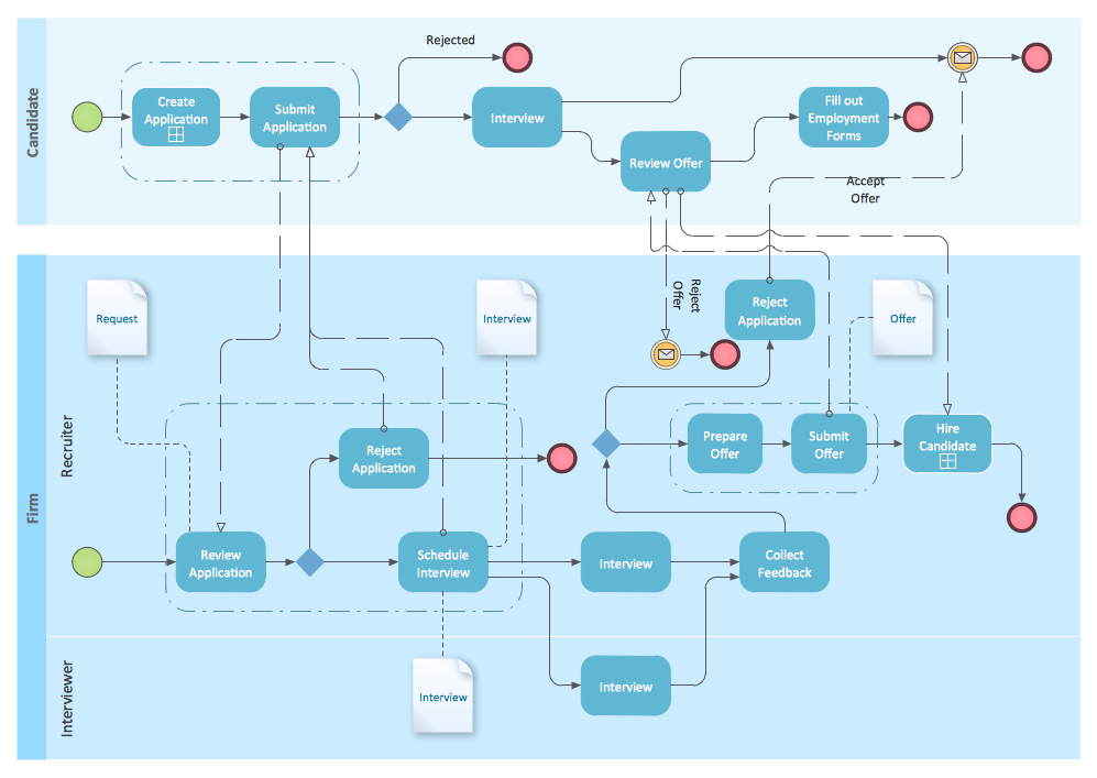
Business process modeling is known in the corporate world as an excellent tool which can speak. Business process flowcharts, diagrams and maps are used to define the business processes in terms of inputs and outputs, to visually represent and effectively explain complex business processes of an enterprise, and also showcase decisions on a single piece of paper. The process of business process mapping supposes the use of special business process flowchart symbols predefined by Business Process Modeling Notation (BPMN) and taking their roots from the data processing diagrams and programming flow charts. In other words the BPMN standard notation is a common language used for business process design and implementation, that guarantees a clarity of designed Business Process Flowcharts for all business analysts, technical developers and business managers. The ability to create professionally-looking Business Process flowcharts, maps and diagrams, is provided by powerful ConceptDraw PRO software and the Business Process Mapping solution included to ConceptDraw Solution Park.Basic Flowchart Symbols and Meaning
Flowcharts are the best for visually representation the business processes and the flow of a custom-order process through various departments within an organization. ConceptDraw PRO diagramming and vector drawing software extended with Flowcharts solution offers the full set of predesigned basic flowchart symbols which are gathered at two libraries: Flowchart and Flowcharts Rapid Draw. Among them are: process, terminator, decision, data, document, display, manual loop, and many other specific symbols. The meaning for each symbol offered by ConceptDraw gives the presentation about their proposed use in professional Flowcharts for business and technical processes, software algorithms, well-developed structures of web sites, Workflow diagrams, Process flow diagram and correlation in developing on-line instructional projects or business process system. Use of ready flow chart symbols in diagrams is incredibly useful - you need simply drag desired from the libraries to your document and arrange them in required order. There are a few serious alternatives to Visio for Mac, one of them is ConceptDraw PRO. It is one of the main contender with the most similar features and capabilities.
Process Flowchart Symbols
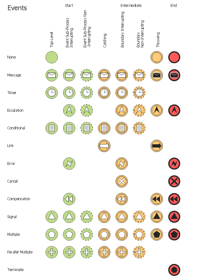
The Process Flowchart or Process Flowchart Diagram (PFD) is a visual representation relations between major parts of the system, the steps in a process, and even connections between various systems. The possibility to easy create professional-looking and attractive Process Flowcharts, Business Process Diagrams and Maps which visualize the steps of complex processes is provided by Business Process Diagram Solution from the Business Processes Area of ConceptDraw Solution Park and 16 libraries with 230 process flowchart symbols from BPMN 1.2 and BPMN 2.0.The vector stencils library "Events" contains 17 symbols: start, intermediate and end events and none events, message, timer, error, escalation, cancel, compensation, conditional, link, signal, terminate, multiple and parralel multiple events, off-page connectors (catching and throwing).
Use these shapes for drawing business process diagrams (BPMN 2.0) using the ConceptDraw PRO diagramming and vector drawing software.
An Event is something that happens during the course of a business process. These events affect the flow of the process and usually have a cause or an impact. There are three types of Events, based on when they affect the flow: Start, Intermediate and End.
The example "Design elements - Events BPMN 2.0" is included in the Business Process Diagram solution from the Business Processes area of ConceptDraw Solution Park.
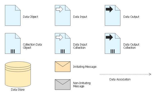
The vector stencils library "Data" contains 10 data symbols: data object, collection data object, data input and output, data input and output collections, data store, initiating and non-initiating messages, data association.
Use these shapes for drawing business process diagrams (BPMN 2.0) using the ConceptDraw PRO diagramming and vector drawing software.
"Artifacts allow developers to bring some more information into the model/ diagram. In this way the model/ diagram becomes more readable. There are three pre-defined Artifacts and they are:
(1) Data objects: Data objects show the reader which data is required or produced in an activity.
(2) Group: A Group is represented with a rounded-corner rectangle and dashed lines. The group is used to group different activities but does not affect the flow in the diagram.
(3) Annotation: An annotation is used to give the reader of the model/ diagram an understandable impression." [Business Process Model and Notation. Wikipedia]
The example "Design elements - Data BPMN 2.0" is included in the Business Process Diagram solution from the Business Processes area of ConceptDraw Solution Park.
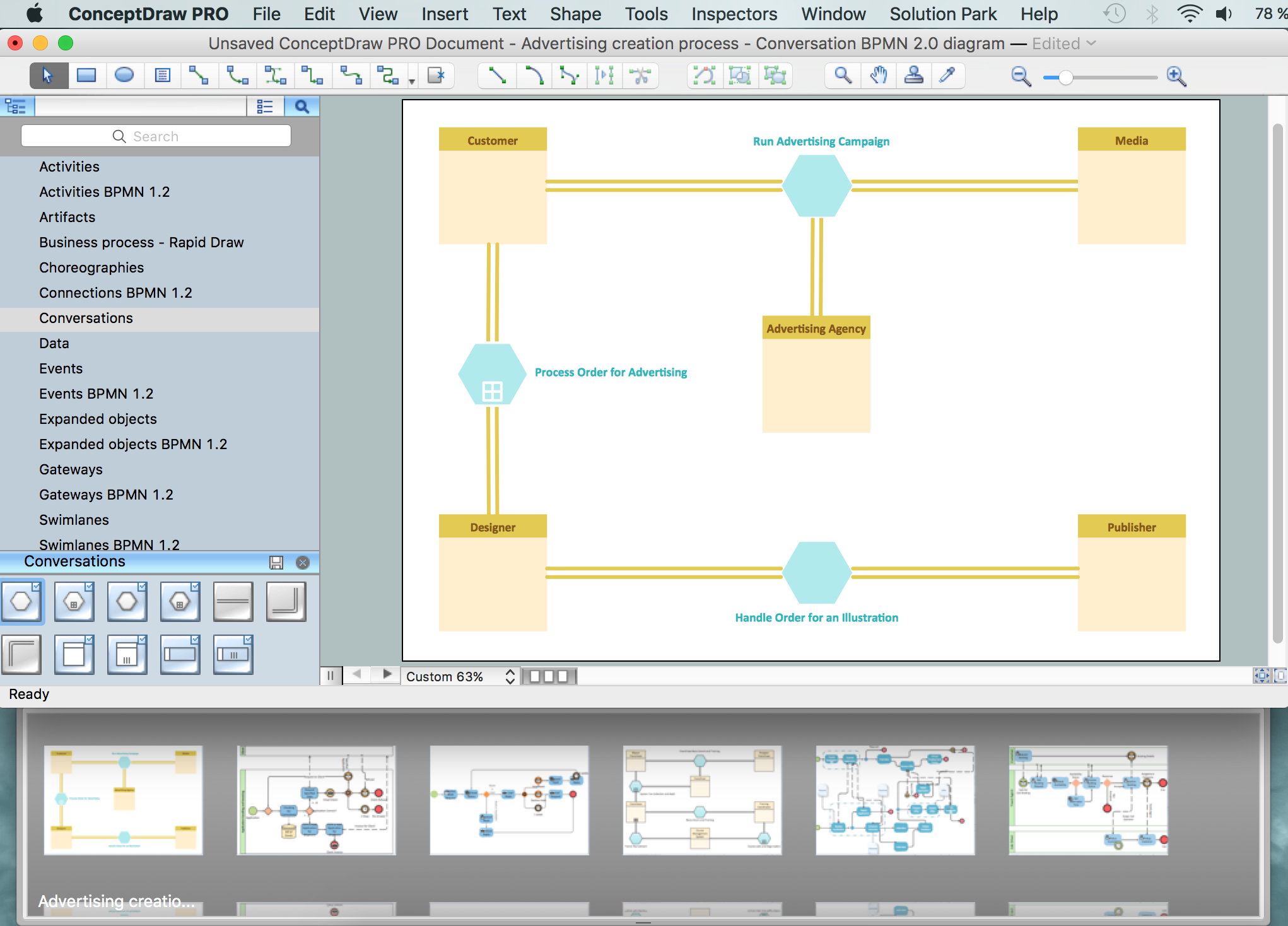
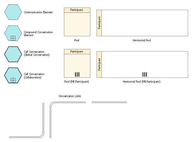
The vector stencils library "Conversations" contains 11 symbols: communication element, compound conversation element, call conversation (global and collaboration), conversation links, pools. Use these shapes for drawing BPMN 2.0 conversation diagrams using the ConceptDraw PRO diagramming and vector drawing software.
"Conversation-Model.
The new Conversation-Model is used to model a "who with whom and what"-view of processes. All process participants can be included in a compact form of modeling as long as denoting which communication is involved.
Process participants are represented as Pools (collapsed...) in Conversation-Models. The Communication-Shape defines a set of logically related message exchanges which are tied to Pools via Conversation-Links. If there is a multi-instanced Pool (also introduced with BPMN 2.0) involved, a Forked Conversation-Link is used for it.
Furthermore Sub-Conversations can be used to define abstractions." [en.bpmn-community.org/ tutorials/ 34/ ]
The example "Design elements - Conversations (BPMN 2.0)" is included in the Business Process Diagram solution from the Business Processes area of ConceptDraw Solution Park.
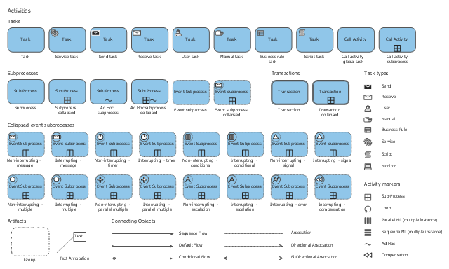
The vector stencils library "Activities" contains 35 symbols for drawing business process diagrams (Business Process Model and Notation) using the ConceptDraw PRO diagramming and vector drawing software.
"An activity is represented with a rounded-corner rectangle and describes the kind of work which must be done. Task. A task represents a single unit of work that is not or cannot be broken down to a further level of business process detail without diagramming the steps in a procedure (which is not the purpose of BPMN). Sub-process. Used to hide or reveal additional levels of business process detail. When collapsed, a sub-process is indicated by a plus sign against the bottom line of the rectangle; when expanded, the rounded rectangle expands to show all flow objects, connecting objects, and artifacts. Has its own self-contained start and end events; sequence flows from the parent process must not cross the boundary. Transaction. A form of sub-process in which all contained activities must be treated as a whole; i.e., they must all be completed to meet an objective, and if any one of them fails, they must all be compensated (undone). Transactions are differentiated from expanded sub-processes by being surrounded by a double border. Call Activity. A point in the process where a global process or a global Task is reused. A call activity is differentiated from other activity types by a bolded border around the activity area." [Business Process Model and Notation. Wikipedia]
The shapes example "Design elements - Activities BPMN 2.0" is included in the Business Process Diagram solution from the Business Processes area of ConceptDraw Solution Park.
The vector stencils library "Business process BPMN 1.2 (Rapid Draw)" contains 12 symbols of objects, roles swimlanes, and task icons for creating the business process diagrams using the ConceptDraw PRO diagramming and vector drawing software.
"BPMN models consist of simple diagrams constructed from a limited set of graphical elements. For both business users and developers, they simplify understanding business activities' flow and process. BPMN's four basic element categories are:
(1) Flow objects.
Events, activities, gateways.
(2) Connecting objects.
Sequence flow, message flow, association
(3) Swim lanes.
Pool, lane.
(4) Artifacts.
Data object, group, annotation.
These four categories enable creation of simple business process diagrams (BPDs). BPDs also permit making new types of flow object or artifact, to make the diagram more understandable. ...
Task.
A task represents a single unit of work that is not or cannot be broken down to a further level of business process detail without diagramming the steps in a procedure (which is not the purpose of BPMN)." [Business Process Model and Notation. Wikipedia]
The shapes example "Design elements - Business process BPMN 1.2 (Rapid Draw)" is included in the Business Process Diagram solution from the Business Processes area of ConceptDraw Solution Park.
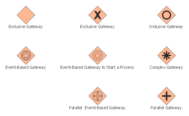
The vector stencils library "Gateways" contains 8 symbols of exclusive, event-based, parallel, inclusive and complex gateways.
Use these shapes for creating the business process diagrams using the ConceptDraw PRO diagramming and vector drawing software.
"Gateway.
A gateway is represented with a diamond shape and determines forking and merging of paths, depending on the conditions expressed.
Exclusive.
Used to create alternative flows in a process because only one of the paths can be taken, it is called exclusive.
Event Based.
The condition determining the path of a process is based on an evaluated event.
Parallel.
Used to create parallel paths without evaluating any conditions.
Inclusive.
Used to create alternative flows where all paths are evaluated.
Exclusive Event Based.
An event is being evaluated to determine which of mutually exclusive paths will be taken.
Complex.
Used to model complex synchronization behavior.
Parallel Event Based.
Two parallel process are started based on an event but there is no evaluation of the event." [Business Process Model and Notation. Wikipedia]
The example "Design elements - Gateways BPMN 2.0" is included in the Business Process Diagram solution from the Business Processes area of ConceptDraw Solution Park.
BPMN
You need to draw professional looking BPMN diagrams quick and easy? Pay please your attention on ConceptDraw PRO diagramming and vector drawing software. Extended with Business Process Diagram Solution from the Business Processes Area it will be ideal for your.- BPMN 2.0 | Business Process Diagrams | Business Process Model ...
- BPMN 2.0 | Business Process Modeling Notation | Process ...
- Business Process Model and Notation | Process Flowchart | BPMN ...
- Fishbone Diagrams | Sales Steps | BPMN 2.0 | Filled Shopping Cart ...
- Bpmn Icons Png
- Basic Flowchart Symbols and Meaning | Business feedback loop ...
- Design elements - Choreographies BPMN 2.0 | Social Brand ...
- Infographic Icon Event Png
- Cartoon Taxi In Png
- Business Analyst Clipart Png
- Entity Relationship Diagram Symbols | Business Process Diagrams ...
- Booking Icon Png
- Value stream map parts | Logistics - Choreography BPMN 2.0 ...
- Swimlanes BPMN 1.2 - Vector stencils library | Composition ...
- Taxi Illustration Png
- Reservation Icon Png
- Symbol Of Objective Png Icon
- UK labour market categories | HR symbols - Vector stencils library ...
- Data Base Symbol Lean Png
- Arrows Infographic Icons Png





.png--diagram-flowchart-example.png)
