How To use House Electrical Plan Software


How To Draw Building Plans

How To use Appliances Symbols for Building Plan

Create Floor Plans Easily with ConceptDraw DIAGRAM


Emergency Plan

Building Plans with ConceptDraw DIAGRAM

Network Diagramming Software for Design Network Layout Diagrams
_Win_Mac.png "Network Diagramming Software for Design <br>Network Layout Diagrams *")

How to create Cafe Floor Plan Design

Restaurant Floor Plans Software

Restaurant Floor Plans Software
Building Drawing Software for Design Piping Plan

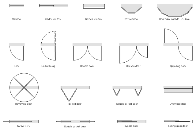
The vector stencils library "Windows and doors" contains 18 window and door shapes.
Use it for drawing your basic floor plans with ConceptDraw PRO diagramming and vector drawing software.
The floorplan shapes example "Design elements - Windows and doors" is included in the Basic Floor Plans solution from the Building Plans area of ConceptDraw Solution Park.
Use it for drawing your basic floor plans with ConceptDraw PRO diagramming and vector drawing software.
The floorplan shapes example "Design elements - Windows and doors" is included in the Basic Floor Plans solution from the Building Plans area of ConceptDraw Solution Park.
Floorplan shapes
Building Drawing Software for Design Sport Fields

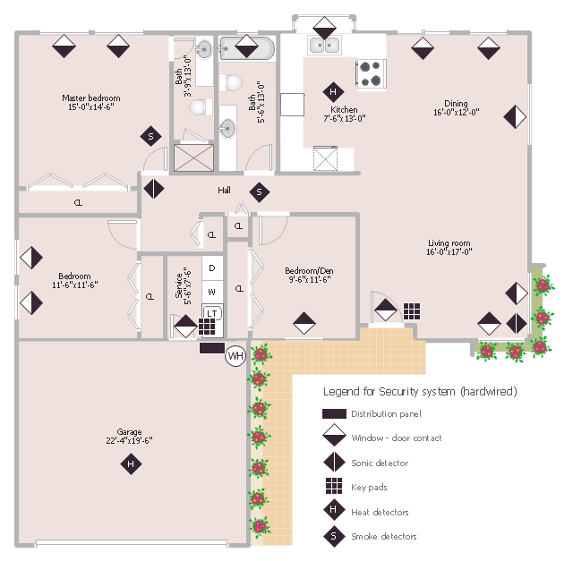
This sample was created on the base of the floor plan with security system device symbols from the website of the California State University, Sacramento. [imet.csus.edu/ imet1/ denyer/ mhs_ denyer/ drafting/ arch_ ch_ 31/ 31-28.jpg]
Legend for the security system hardware includes distribution panel, window-door contact, sonic detector, key pads, heat detectors, smoke detectors.
The example "Security system floor plan" was created using the ConceptDraw PRO diagramming and vector drawing software extended with the Security and Access Plans solution from the Building Plans area of ConceptDraw Solution Park.
Security system floor plan
Technical Drawing Software

The vector stencils library "Network layout floorplan" contain 34 symbol icons for drawing computer network floor plans, communication equipment layouts, and structured cabling diagrams.
"Structured cabling is building or campus telecommunications cabling infrastructure that consists of a number of standardized smaller elements (hence structured) called subsystems. ...
Structured cabling design and installation is governed by a set of standards that specify wiring data centers, offices, and apartment buildings for data or voice communications using various kinds of cable, most commonly category 5e (CAT-5e), category 6 (CAT-6), and fibre optic cabling and modular connectors. These standards define how to lay the cabling in various topologies in order to meet the needs of the customer, typically using a central patch panel (which is normally 19 inch rack-mounted), from where each modular connection can be used as needed. Each outlet is then patched into a network switch (normally also rack-mounted) for network use or into an IP or PBX (private branch exchange) telephone system patch panel." [Structured cabling. Wikipedia]
The design elements example "Network layout floorplan - Vector stencils library" was created using the ConceptDraw PRO diagramming and vector drawing software extended with the Network Layout Floor Plans solution from the Computer and Networks area of ConceptDraw Solution Park.
PC

Scanner

Switch

Router

Modem

Hub

Rack Mount

Printer

Floor Mounted Outlet

Single Outlet

Duplex Outlet

Direct bus cable

Tops or bottoms bus cable

Side to side bus cable

Multi-tree bus cable

Bottom to side bus cable

Sides bus cable

Door

Door, threshold

Door, stop

Door, stop, threshold

Door, frame

Door, frame, threshold

Door, frame, stop

Door, frame, stop, threshold

Window

Window, sill

Window, sash

Window, sash, sill

Window, frame

Window, frame, sill

Window, frame, sash

Window, frame, sash, sill

Room planning with ConceptDraw DIAGRAM

Network Diagramming Software for Network Active Directory Diagrams

- Design elements - Doors and windows | How To use House ...
- Design elements - Doors and windows | Network Layout Floor Plans ...
- How To use House Electrical Plan Software | Design elements ...
- Window Symbols On A Floor Plan
- Air handler- HVAC plan | Design elements - Windows and doors ...
- Floor Plan Symbol For Slding Glass Doors
- Design elements - Windows and doors | How To Make a Floor Plan ...
- Doors - Vector stencils library | Design elements - Windows and ...
- Security system floor plan | Design elements - Doors and windows ...
- How To Draw Bay Windows On A Floor Plan
- House ventilation | Floor Plans | Design elements - Network layout ...
- Design elements - Doors and windows | Coffee shop floor plan ...
- Design elements - Doors and windows | Mini Hotel Floor Plan . Floor ...
- How To use Appliances Symbols for Building Plan | Design ...
- Design elements - Doors and windows | Home floor plan template ...
- How To Draw A Floor Plan Window Frame
- Sliding Windows Floor Plan
- ConceptDraw DIAGRAM Compatibility with MS Visio | Design ...
- Doors - Vector stencils library | Design elements - Doors and ...
- Banquet Hall Plan Software | Restaurant Floor Plan Software ...