UML Activity Diagram

S Video Connection

UML Notation

The vector stencils library "Rack diagrams" contains 33 rack design elements for drawing the computer network server rack diagrams.
"A 19-inch rack is a standardized frame or enclosure for mounting multiple equipment modules. Each module has a front panel that is 19 inches (482.6 mm) wide, including edges or ears that protrude on each side which allow the module to be fastened to the rack frame with screws. ...
Equipment designed to be placed in a rack is typically described as rack-mount, rack-mount instrument, a rack mounted system, a rack mount chassis, subrack, rack mountable, or occasionally simply shelf. The height of the electronic modules is also standardized as multiples of 1.75 inches (44.45 mm) or one rack unit or U (less commonly RU). The industry standard rack cabinet is 42U tall. ...
19-inch racks in 2-post or 4-post form hold most equipment in modern data centers, ISP facilities and professionally designed corporate server rooms. They allow for dense hardware configurations without occupying excessive floorspace or requiring shelving." [19-inch rack. Wikipedia]
The clip art example "Rack diagrams - Vector stencils library" was created using the ConceptDraw PRO diagramming and vector drawing software extended with the Rack Diagrams solution from the Computer and Networks area of ConceptDraw Solution Park.
19 inch Rack with Rails

Rack

Rack rails

Rack rails (half-width)
-rack-diagrams---vector-stencils-library.png--diagram-flowchart-example.png)
Single rack rail

Xserve RAID

XServe

1U tray

1U spacer

2U server

1U Ethernet Switch/Hub

2U Ethernet Switch/Hub

1U power strip

1U KVM switch

1U patch panel

Rackmount UPS

Cisco switch (WS-C3560-24PS-S)
-rack-diagrams---vector-stencils-library.png--diagram-flowchart-example.png)
Cisco switch (WS-C3560-48TS-S)
-rack-diagrams---vector-stencils-library.png--diagram-flowchart-example.png)
Cisco switch (WS-C2960-48TT-L)
-rack-diagrams---vector-stencils-library.png--diagram-flowchart-example.png)
Cisco switch (WS-C2960-48TC-L)
-rack-diagrams---vector-stencils-library.png--diagram-flowchart-example.png)
Cisco switch (WS-C2960-24TT-L)
-rack-diagrams---vector-stencils-library.png--diagram-flowchart-example.png)
Cisco switch (WS-C2960-24TC-L)
-rack-diagrams---vector-stencils-library.png--diagram-flowchart-example.png)
7U rackmount LCD monitor

8U rackmount LCD monitor

Fiber optic patch panel (type A)
-rack-diagrams---vector-stencils-library.png--diagram-flowchart-example.png)
Fiber optic patch panel (type B)
-rack-diagrams---vector-stencils-library.png--diagram-flowchart-example.png)
Fiber optic patch panel (type C)
-rack-diagrams---vector-stencils-library.png--diagram-flowchart-example.png)
3U server

2U RAID array

3U RAID array

Managed UPS

1U 19'' LCD monitor keyboard

1U server

Process Flowchart


HelpDesk
How to Remove ConceptDraw Products from Mac and PC

ConceptDraw PRO Compatibility with MS Visio

Diagramming Software for Design UML Activity Diagrams
")

The vector stencils library "American football positions" contains 38 american football (gridiron) players symbols.
Use it for drawing diagrams of American football positions in the ConceptDraw PRO diagramming and vector drawing software extended with the Football solution from the Sport area of ConceptDraw Solution Park.
Use it for drawing diagrams of American football positions in the ConceptDraw PRO diagramming and vector drawing software extended with the Football solution from the Sport area of ConceptDraw Solution Park.
Defensive tackle (DT)
-american-football-positions---vector-stencils-library.png--diagram-flowchart-example.png)
Defensive end (DE)
-american-football-positions---vector-stencils-library.png--diagram-flowchart-example.png)
Linebackers (LB)
-american-football-positions---vector-stencils-library.png--diagram-flowchart-example.png)
Cornerback (CB)
-american-football-positions---vector-stencils-library.png--diagram-flowchart-example.png)
Safety (S)
-american-football-positions---vector-stencils-library.png--diagram-flowchart-example.png)
Quarterback (QB)
-american-football-positions---vector-stencils-library.png--diagram-flowchart-example.png)
Running back (RB)
-american-football-positions---vector-stencils-library.png--diagram-flowchart-example.png)
Wide receiver (WR)
-american-football-positions---vector-stencils-library.png--diagram-flowchart-example.png)
Tight end (TE)
-american-football-positions---vector-stencils-library.png--diagram-flowchart-example.png)
Center (C)
-american-football-positions---vector-stencils-library.png--diagram-flowchart-example.png)
Offensive guard (G)
-american-football-positions---vector-stencils-library.png--diagram-flowchart-example.png)
Offensive tackle (T)
-american-football-positions---vector-stencils-library.png--diagram-flowchart-example.png)
Kicker (K)
-american-football-positions---vector-stencils-library.png--diagram-flowchart-example.png)
Holder (H)
-american-football-positions---vector-stencils-library.png--diagram-flowchart-example.png)
Long snapper (LS)
-american-football-positions---vector-stencils-library.png--diagram-flowchart-example.png)
Punter (P)
-american-football-positions---vector-stencils-library.png--diagram-flowchart-example.png)
Kickoff specialist (KOS)
-american-football-positions---vector-stencils-library.png--diagram-flowchart-example.png)
Punt returner (PR)
-american-football-positions---vector-stencils-library.png--diagram-flowchart-example.png)
Kick returner (KR)
-american-football-positions---vector-stencils-library.png--diagram-flowchart-example.png)
Defensive tackle (DT)
-american-football-positions---vector-stencils-library.png--diagram-flowchart-example.png)
Defensive end (DE)
-american-football-positions---vector-stencils-library.png--diagram-flowchart-example.png)
Linebackers (LB)
-american-football-positions---vector-stencils-library.png--diagram-flowchart-example.png)
Cornerback (CB)
-american-football-positions---vector-stencils-library.png--diagram-flowchart-example.png)
Safety (S)
-american-football-positions---vector-stencils-library.png--diagram-flowchart-example.png)
Quarterback (QB)
-american-football-positions---vector-stencils-library.png--diagram-flowchart-example.png)
Running back (RB)
-american-football-positions---vector-stencils-library.png--diagram-flowchart-example.png)
Wide receiver (WR)
-american-football-positions---vector-stencils-library.png--diagram-flowchart-example.png)
Tight end (TE)
-american-football-positions---vector-stencils-library.png--diagram-flowchart-example.png)
Center (C)
-american-football-positions---vector-stencils-library.png--diagram-flowchart-example.png)
Guard (G)
-american-football-positions---vector-stencils-library.png--diagram-flowchart-example.png)
Tackle (T)
-american-football-positions---vector-stencils-library.png--diagram-flowchart-example.png)
Kicker (K)
-american-football-positions---vector-stencils-library.png--diagram-flowchart-example.png)
Holder (H)
-american-football-positions---vector-stencils-library.png--diagram-flowchart-example.png)
Long snapper (LS)
-american-football-positions---vector-stencils-library.png--diagram-flowchart-example.png)
Punter (P)
-american-football-positions---vector-stencils-library.png--diagram-flowchart-example.png)
Kickoff specialist (KOS)
-american-football-positions---vector-stencils-library.png--diagram-flowchart-example.png)
Punt returner (PR)
-american-football-positions---vector-stencils-library.png--diagram-flowchart-example.png)
Kick returner (KR)
-american-football-positions---vector-stencils-library.png--diagram-flowchart-example.png)
The vector stencils library "Switches and relays" contains 58 symbols of electrical contacts, switches, relays, circuit breakers, selectors, connectors, disconnect devices, switching circuits, current regulators, and thermostats for electrical devices.
Use these shapes for drawing electrical diagrams in the ConceptDraw PRO diagramming and vector drawing software extended with the Electrical Engineering solution from the Engineering area of ConceptDraw Solution Park.
www.conceptdraw.com/ solution-park/ engineering-electrical
Use these shapes for drawing electrical diagrams in the ConceptDraw PRO diagramming and vector drawing software extended with the Electrical Engineering solution from the Engineering area of ConceptDraw Solution Park.
www.conceptdraw.com/ solution-park/ engineering-electrical
SPST

SPDT

DPST

DPDT

Make contact

Break contact

Two way contact

Passing make-contact

Spring return

Stay put

Limit switch

Circuit breaker

Spring return 2

Spring return 3

Limit switch n/o

Limit switch n/c

2 position switch

3 position switch

4 position switch

Manual switch

Pushbutton make

Pushbutton break

Pushbutton 2-circuit

Selector switch

Shorting selector

Proximity limit switch

Time delay make

Time delay break

Time delay make 2

Time delay break 2

Safety interlock

Flow actuated

Liquid level actuated

Liquid level actuated 2

Gas flow actuated

Pressure actuated

Temperature actuated

Thermostat

Temperature switch

Inertia switch

Mercury switch

Mercury switch 2

Fuse

Switch disconnector

Isolator

Change-over contact

Relay contacts

Relay coil

Pilot light

Pilot light, push-to-test

Relay, alternating-current

Relay, magnetically polarized

Relay, slow-operate

Relay, slow-release

Relay

Relay, high speed

Relay, mechanically latched

Relay, permanent

Project — Assigning Resources

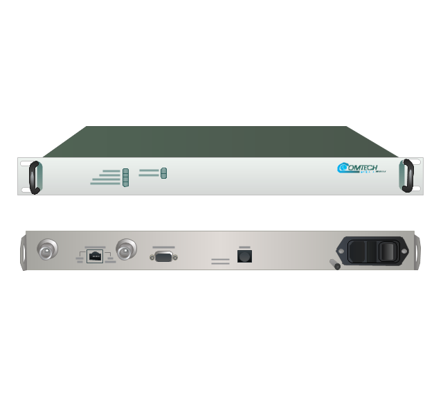
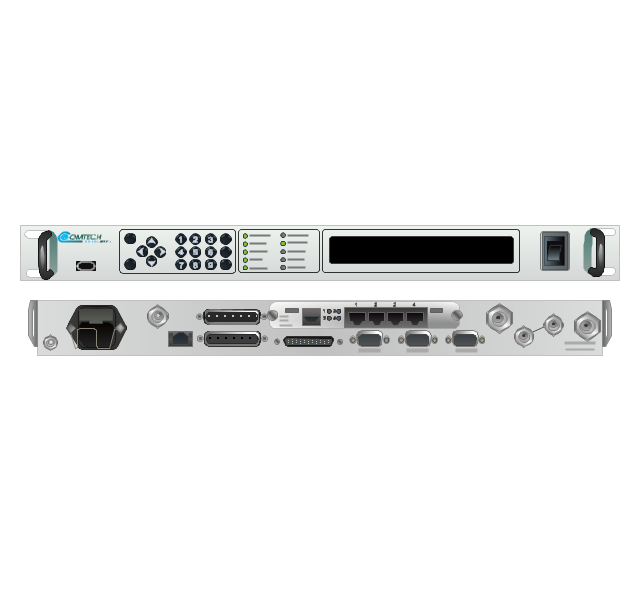
The vector stencils library "Comtech" contains 9 icons of Comtech devices for drawing computer network diagrams and telecommunication equipment layouts.
"Comtech EF Data Corporation ... communication solutions encompass Advanced VSAT Solutions, Modems, RAN & WAN Optimization, Network & Bandwidth Management, RF Products ... for fixed and mobile/ transportable satellite-based applications." [comtechefdata.com]
The clip art example "Comtech - Vector stencils library" was created using the ConceptDraw PRO diagramming and vector drawing software extended with the Telecommunication Network Diagrams solution from the Computer and Networks area of ConceptDraw Solution Park.
CDD-562L & CDD-562LEN dual IP demodulator
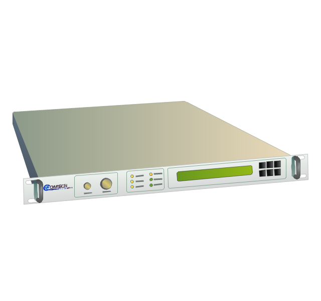
CDM-700G high-speed satellite modem
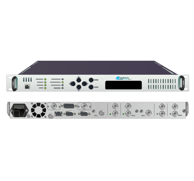
CDM-710G high-speed satellite modem
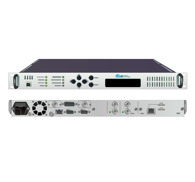
SLM-5650A satellite modem
UT-4505 series up converters
LPOD C- or Ku-band block up converters
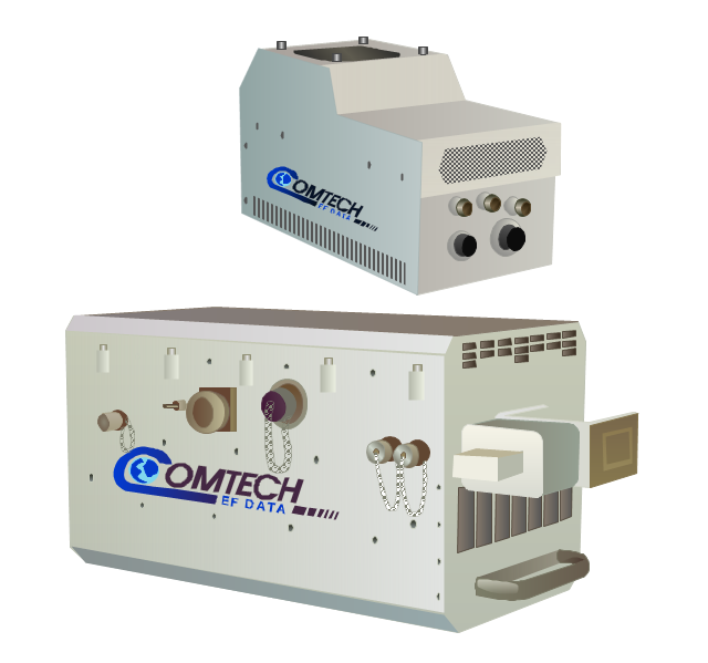
MBT-4000/ MBT-4000B outdoor multi-band RF transceiver
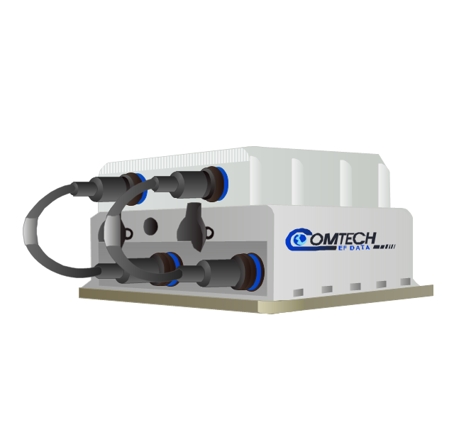
High-Power Outdoor C-, X- & Ku-band outdoor amplifier (HPOD)
-comtech---vector-stencils-library.png--diagram-flowchart-example.png)
Indoor solid state power amplifiers (SSPA)
-comtech---vector-stencils-library.png--diagram-flowchart-example.png)
Cross-Functional Flowchart (Swim Lanes)

Data Flow Diagram

- Uml Activity Diagrams For C
- Space Station Clipart Black And White
- Players Black And White Diagrams To Draw
- Final object schematic - IDEF3 diagram | Vector stencils library ...
- Seven Basic Tools of Quality - Histogram | Histogram example - Age ...
- Banking System C Flowchart
- A Diagram Of A Flow C
- Trees and plants - Vector stencils library | Fire Evacuation Plan ...
- UML Activity Diagram | Diagramming Software for Design UML ...
- Simple Black And White Image Of Football Drawing For Stencil
- Factory Vector Png Black
- Basic Flowchart Symbols and Meaning | Audit Flowchart Symbols ...
- Toy Clipart Black And White
- Basic Flowchart Symbols and Meaning | Types of Flowcharts ...
- Rocket Clip Art Black And White
- ABC - Vector stencils library | Abc Lower Case Letters Black And White
- Standard Universal Audio & Video Connection Types | Terminals ...
- 24 Vector Black
- Standard Universal Audio & Video Connection Types | Audio and ...
- Ip Switch Clipart Black And White