The vector stencils library "Sales symbols" contains 55 sales pictograms.
Use these icon set to draw your sales flowcharts, workflow diagrams and process charts with the ConceptDraw PRO diagramming and vector drawing software.
The vector stencils library "Sales symbols" is included in the Sales Flowcharts solution from the Marketing area of ConceptDraw Solution Park.
Use these icon set to draw your sales flowcharts, workflow diagrams and process charts with the ConceptDraw PRO diagramming and vector drawing software.
The vector stencils library "Sales symbols" is included in the Sales Flowcharts solution from the Marketing area of ConceptDraw Solution Park.
This interactive voice response (IVR) flowchart sample shows the store reporting process flow.
"Call centers use IVR systems to identify and segment callers. The ability to identify customers allows services to be tailored according to the customer profile. The caller can be given the option to wait in the queue, choose an automated service, or request a callback. The system may obtain caller line identification (CLI) data from the network to help identify or authenticate the caller. Additional caller authentication data could include account number, personal information, password and biometrics (such as voice print).
When an IVR system answers multiple phone numbers the use of DNIS ensures that the correct application and language is executed. A single large IVR system can handle calls for thousands of applications, each with its own phone numbers and script.
IVR also enables customer prioritization. In a system wherein individual customers may have a different status the service will automatically prioritize the individual's call and move customers to the front of a specific queue. Prioritization could also be based on the DNIS and call reason." [Interactive voice response. Wikipedia]
The IVR diagram example "Store reporting flowchart" was created using the ConceptDraw PRO diagramming and vector drawing software extended with the Interactive Voice Response Diagrams solution from the Computer and Networks area of ConceptDraw Solution Park.
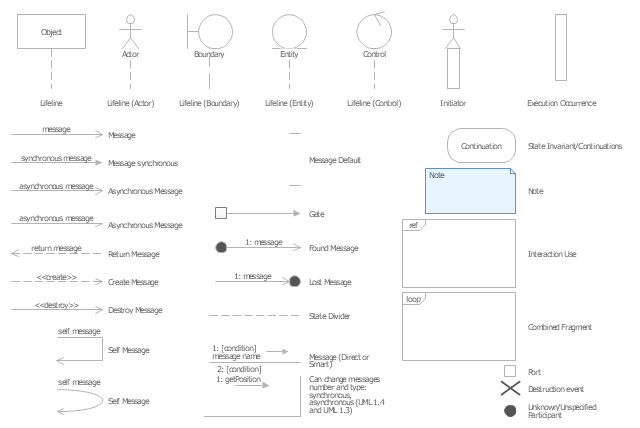
The vector stencils library "UML sequence diagrams" contains 50 symbols for the ConceptDraw PRO diagramming and vector drawing software.
"Sequence diagram ... building blocks.
If the lifeline is that of an object, it demonstrates a role. Note that leaving the instance name blank can represent anonymous and unnamed instances.
Messages, written with horizontal arrows with the message name written above them, display interaction. Solid arrow heads represent synchronous calls, open arrow heads represent asynchronous messages, and dashed lines represent reply messages. If a caller sends a synchronous message, it must wait until the message is done, such as invoking a subroutine. If a caller sends an asynchronous message, it can continue processing and doesn’t have to wait for a response. Asynchronous calls are present in multithreaded applications and in message-oriented middleware. Activation boxes, or method-call boxes, are opaque rectangles drawn on top of lifelines to represent that processes are being performed in response to the message (ExecutionSpecifications in UML).
Objects calling methods on themselves use messages and add new activation boxes on top of any others to indicate a further level of processing.
When an object is destroyed (removed from memory), an X is drawn on top of the lifeline, and the dashed line ceases to be drawn below it (this is not the case in the first example though). It should be the result of a message, either from the object itself, or another.
A message sent from outside the diagram can be represented by a message originating from a filled-in circle (found message in UML) or from a border of the sequence diagram (gate in UML)." [Sequence diagram. Wikipedia]
The example "Design elements - UML sequence diagrams" is included in the Rapid UML solution from the Software Development area of ConceptDraw Solution Park.
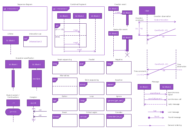
The vector stencils library "Sequence diagram" contains 32 SysML symbols.
Use it to design your sequence diagrams using ConceptDraw PRO diagramming and vector drawing software.
"A sequence diagram shows, as parallel vertical lines (lifelines), different processes or objects that live simultaneously, and, as horizontal arrows, the messages exchanged between them, in the order in which they occur. This allows the specification of simple runtime scenarios in a graphical manner. ...
If the lifeline is that of an object, it demonstrates a role. Leaving the instance name blank can represent anonymous and unnamed instances.
Messages, written with horizontal arrows with the message name written above them, display interaction. Solid arrow heads represent synchronous calls, open arrow heads represent asynchronous messages, and dashed lines represent reply messages. If a caller sends a synchronous message, it must wait until the message is done, such as invoking a subroutine. If a caller sends an asynchronous message, it can continue processing and doesn’t have to wait for a response. Asynchronous calls are present in multithreaded applications and in message-oriented middleware. Activation boxes, or method-call boxes, are opaque rectangles drawn on top of lifelines to represent that processes are being performed in response to the message (ExecutionSpecifications in UML).
Objects calling methods on themselves use messages and add new activation boxes on top of any others to indicate a further level of processing.
When an object is destroyed (removed from memory), an X is drawn on top of the lifeline, and the dashed line ceases to be drawn below it (this is not the case in the first example though). It should be the result of a message, either from the object itself, or another.
A message sent from outside the diagram can be represented by a message originating from a filled-in circle (found message in UML) or from a border of the sequence diagram (gate in UML)." [Sequence diagram. Wikipedia]
The SysML shapes example "Design elements - Sequence diagram" is included in the SysML solution from the Software Development area of ConceptDraw Solution Park.
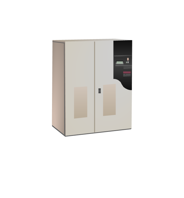
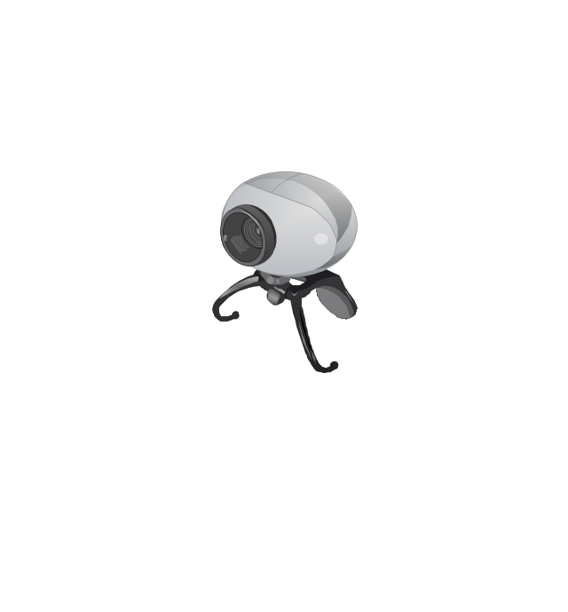
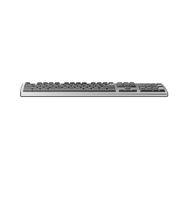
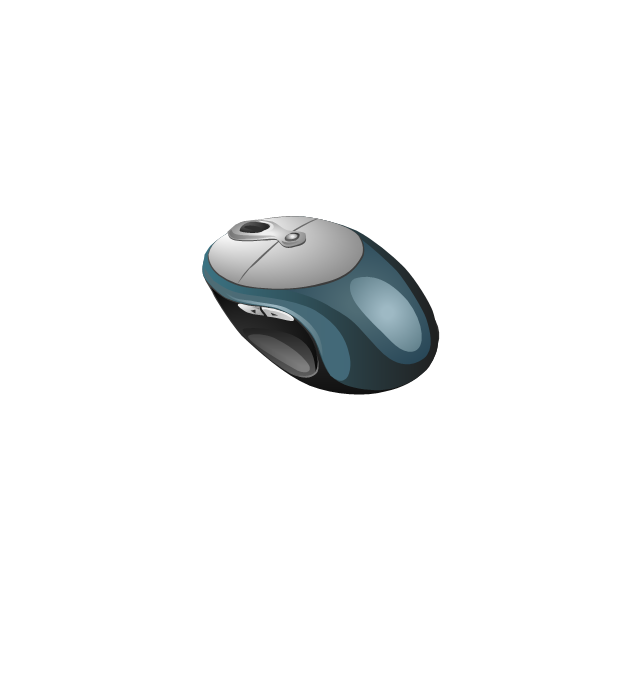
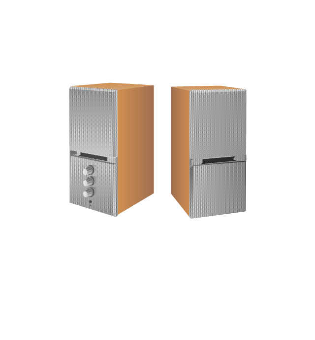
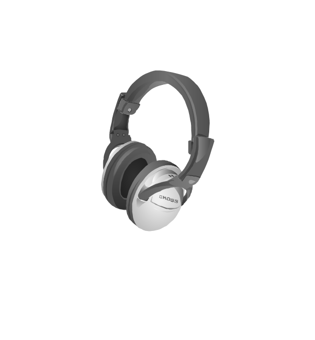
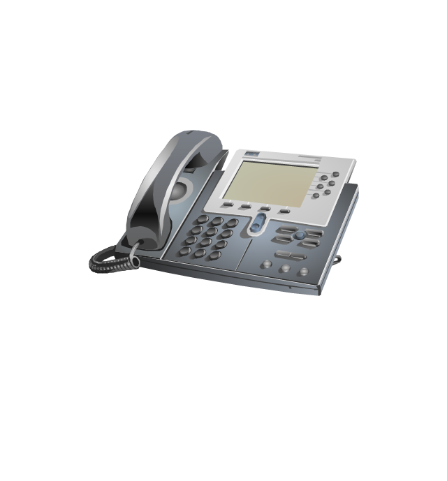
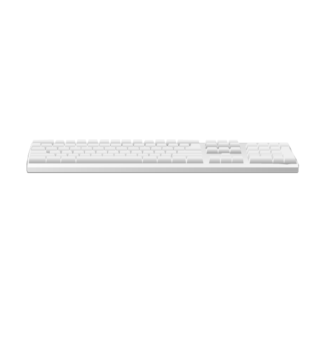
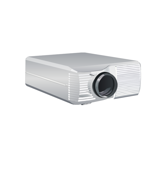
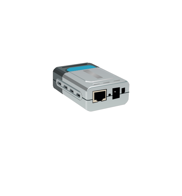
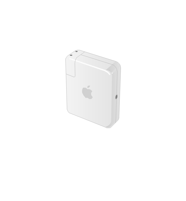
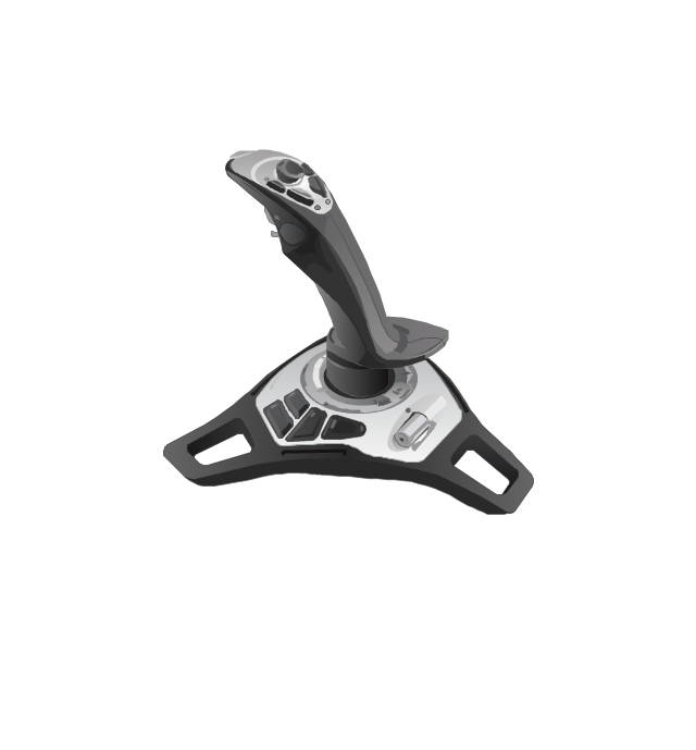
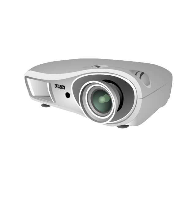
The vector stencils library "Computer peripheral devices" contains 18 clipart images of computer peripheral devices and equipment for drawing network diagrams.
"A peripheral is a device that is connected to a host computer, but not an integral part of it. It expands the host's capabilities but does not form part of the core computer architecture. It is often, but not always, partially or completely dependent on the host.
There are three different types of peripherals:
(1) Input, used to interact with, or send data to the computer (mouse, keyboards, etc.).
(2) Output, which provides output to the user from the computer (monitors, printers, etc.).
(3) Storage, which stores data processed by the computer (hard drives, flash drives, etc.)" [Peripheral. Wikipedia]
The clip art example "Computer peripheral devices - Vector stencils library" was created using the ConceptDraw PRO diagramming and vector drawing software extended with the Computer and Networks solution from the Computer and Networks area of ConceptDraw Solution Park.
This interactive voice response (IVR) diagram sample illustrates the IVR services.
"IVR systems are typically intended to service high call volumes, reduce cost and improve the customer experience. Examples of typical IVR applications are telephone banking, televoting, and credit card services. ...
Voice-Activated Dialing
... (VAD) IVR systems are used to automate routine enquiries to switchboard or PABX (Private Automatic Branch eXchange) operators, and are used in many hospitals and large businesses to reduce the caller waiting time. ...
Entertainment and information.
Some of the largest installed IVR platforms are used for televoting on television game shows, ... which can generate enormous call spikes. Often, the network provider will have to deploy call gapping in the PSTN to prevent network overload. ...
Anonymous access.
IVR systems allow callers to obtain data relatively anonymously. Hospitals and clinics have used IVR systems to allow callers to receive anonymous access to test results. ...
Clinical trials.
IVR systems are used by pharmaceutical companies and contract research organizations to conduct clinical trials and manage the large volumes of data generated. ... Applications include patient randomization and drug supply management. ...
Outbound calling.
IVR systems can be used for outbound calls, as IVR systems are more intelligent than many predictive dialer systems, and can use Call Progress Detection to recognize different line conditions...
Other common IVR services include:
Mobile - Pay-As-You-Go account funding; registration; mobile purchases, such as ring tones and logos;
Banking - balance, payments, transfers, transaction history;
Retail & Entertainment - orders, bookings, credit & debit card payments;
Utilities - meter readings; account look-up, history and balance, payment, consumption history;
Travel — ticket booking, flight information, check-in;
Weather forecasts, water, road and ice conditions" [Interactive voice response. Wikipedia]
The IVR diagram example "IVR services" was created using the ConceptDraw PRO diagramming and vector drawing software extended with the Interactive Voice Response Diagrams solution from the Computer and Networks area of ConceptDraw Solution Park.
The vector stencils library "Sales symbols" contains 55 sales process pictograms.
Use it to design your sales flowcharts, workflow diagrams and process charts by the ConceptDraw PRO diagramming and vector drawing software.
"A sales process is an approach to selling a product or service.
... a "sales process" is presented as consisting of eight steps. These are:
(1) Prospecting / initial contact,
(2) Preapproach - planning the sale,
(3) Identifying and cross questioning,
(4) Need assessment,
(5) Presentation,
(6) Meeting objections,
(7) Gaining commitment,
(8) Follow-up." [Sales process. Wikipedia]
The icons example "Design elements - Sales symbols" is included in the Sales Flowcharts solution from the Marketing area of ConceptDraw Solution Park.
- Men Women Caller Png Logo
- Caller Png
- Sales symbols - Vector stencils library | Marketing - Vector stencils ...
- Sales symbols - Vector stencils library | Paypal Logo Png
- Vector Flat Payment Card Flat Png
- Sales symbols - Vector stencils library
- Email Vector Png
- Sales symbols - Vector stencils library | Business feedback loop ...
- Sales Dashboard | Sales symbols - Vector stencils library | Sales ...
- Basic Flowchart Symbols and Meaning | Sales symbols - Vector ...
- Shopping pictograms - Vector stencils library | Shopping pictograms ...
- Shopping Cart Vector Icon Png
- Cisco people - Vector stencils library | Design elements - Cisco ...
- Cisco LAN - Vector stencils library | Sales symbols - Vector stencils ...
- Apple Wireless Mouse | Marketing - Vector stencils library | Design ...
- Windows 8 apps - Vector stencils library | Process Flowchart ...
- Usb Vector Png
- Web Page Vector Png
- Sales Man Vector Png
- Credit Card Clipart Vector Png


