- Electric and Telecom Plans Free
- Fire and Emergency Plans Free
- Floor Plans Free
- Plant Layout Plans Free
- School and Training Plans Free
- Seating Plans Free
- Security and Access Plans Free
- Site Plans Free
- Sport Field Plans Free
- Business Process Diagrams Free
- Business Process Mapping Free
- Classic Business Process Modeling Free
- Cross-Functional Flowcharts Free
- Event-driven Process Chain Diagrams Free
- IDEF Business Process Diagrams Free
- Logistics Flow Charts Free
- Workflow Diagrams Free
- ConceptDraw Dashboard for Facebook Free
- Mind Map Exchange Free
- MindTweet Free
- Note Exchange Free
- Project Exchange Free
- Social Media Response Free
- Active Directory Diagrams Free
- AWS Architecture Diagrams Free
- Azure Architecture Free
- Cisco Network Diagrams Free
- Cisco Networking Free
- Cloud Computing Diagrams Free
- Computer Network Diagrams Free
- Google Cloud Platform Free
- Interactive Voice Response Diagrams Free
- Network Layout Floor Plans Free
- Network Security Diagrams Free
- Rack Diagrams Free
- Telecommunication Network Diagrams Free
- Vehicular Networking Free
- Wireless Networks Free
- Comparison Dashboard Free
- Composition Dashboard Free
- Correlation Dashboard Free
- Frequency Distribution Dashboard Free
- Meter Dashboard Free
- Spatial Dashboard Free
- Status Dashboard Free
- Time Series Dashboard Free
- Basic Circle-Spoke Diagrams Free
- Basic Circular Arrows Diagrams Free
- Basic Venn Diagrams Free
- Block Diagrams Free
- Concept Maps Free
- Family Tree Free
- Flowcharts Free
- Basic Area Charts Free
- Basic Bar Graphs Free
- Basic Divided Bar Diagrams Free
- Basic Histograms Free
- Basic Line Graphs Free
- Basic Picture Graphs Free
- Basic Pie Charts Free
- Basic Scatter Diagrams Free
- Aerospace and Transport Free
- Artwork Free
- Audio, Video, Media Free
- Business and Finance Free
- Computers and Communications Free
- Holiday Free
- Manufacturing and Maintenance Free
- Nature Free
- People Free
- Presentation Clipart Free
- Safety and Security Free
- Analog Electronics Free
- Audio and Video Connectors Free
- Basic Circuit Diagrams Free
- Chemical and Process Engineering Free
- Digital Electronics Free
- Electrical Engineering Free
- Electron Tube Circuits Free
- Electronic Block Diagrams Free
- Fault Tree Analysis Diagrams Free
- GHS Hazard Pictograms Free
- Home Automation and Wiring Free
- Mechanical Engineering Free
- One-line Diagrams Free
- Power Сircuits Free
- Specification and Description Language (SDL) Free
- Telecom and AV Circuits Free
- Transport Hazard Pictograms Free
- Data-driven Infographics Free
- Pictorial Infographics Free
- Spatial Infographics Free
- Typography Infographics Free
- Calendars Free
- Decision Making Free
- Enterprise Architecture Diagrams Free
- Fishbone Diagrams Free
- Organizational Charts Free
- Plan-Do-Check-Act (PDCA) Free
- Seven Management and Planning Tools Free
- SWOT and TOWS Matrix Diagrams Free
- Timeline Diagrams Free
- Australia Map Free
- Continent Maps Free
- Directional Maps Free
- Germany Map Free
- Metro Map Free
- UK Map Free
- USA Maps Free
- Customer Journey Mapping Free
- Marketing Diagrams Free
- Matrices Free
- Pyramid Diagrams Free
- Sales Dashboard Free
- Sales Flowcharts Free
- Target and Circular Diagrams Free
- Cash Flow Reports Free
- Current Activities Reports Free
- Custom Excel Report Free
- Knowledge Reports Free
- MINDMAP Reports Free
- Overview Reports Free
- PM Agile Free
- PM Dashboards Free
- PM Docs Free
- PM Easy Free
- PM Meetings Free
- PM Planning Free
- PM Presentations Free
- PM Response Free
- Resource Usage Reports Free
- Visual Reports Free
- House of Quality Free
- Quality Mind Map Free
- Total Quality Management TQM Diagrams Free
- Value Stream Mapping Free
- Astronomy Free
- Biology Free
- Chemistry Free
- Language Learning Free
- Mathematics Free
- Physics Free
- Piano Sheet Music Free
- Android User Interface Free
- Class Hierarchy Tree Free
- Data Flow Diagrams (DFD) Free
- DOM Tree Free
- Entity-Relationship Diagram (ERD) Free
- EXPRESS-G data Modeling Diagram Free
- IDEF0 Diagrams Free
- iPhone User Interface Free
- Jackson Structured Programming (JSP) Diagrams Free
- macOS User Interface Free
- Object-Role Modeling (ORM) Diagrams Free
- Rapid UML Free
- SYSML Free
- Website Wireframe Free
- Windows 10 User Interface Free
ATM UML Diagrams
UML has many types of diagrams. All of them can be divided into two main categories. Some of their types represent structural information, and some represent general types of behavior, for example, various aspects of interaction.
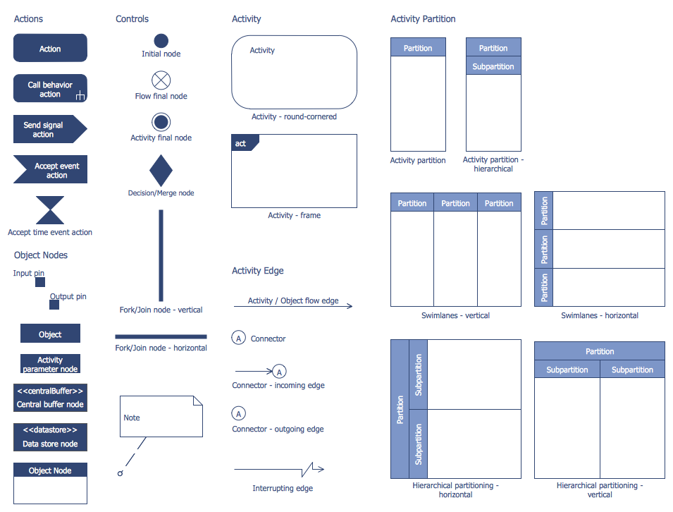
Action diagrams can be referenced to as UML diagrams, which are a graphical representation of the workflows of actions and actions that support iteration, concurrency, and selection. It is known that all action diagrams in the Unified Modeling Language are intended for modeling both organizational and computational processes. There may also be data flows intersecting with the corresponding actions, showing the overall control flow. They may also include other elements to show the flow of data between actions through one or more data stores.
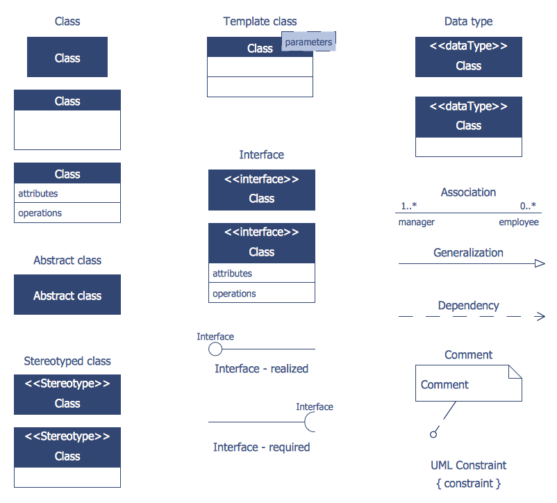
In software development, any class diagram can also be referred to the Unified Modeling Language (UML). It is known to be a type of static structure diagram that should describe the structure of the system in such a way to demonstrate classes of the system, their attributes, methods or operations, and the relationships between objects.
Being the main building block of any object-oriented modeling, the class diagram is widely used for general conceptual modeling of systematic application. It can also be used for detailed modeling, converting models into program code. They can also be used for any necessary data modeling, representing basic elements, interactions in the application, and classes for coding.
To further describe the behavior of systems, these class diagrams can be supplemented with either a UML state machine or a state diagram, which can also be called one of the UML diagrams. You can use the ConceptDraw DIAGRAM charting software to create one of them.
The ATM UML Diagrams solution provides a selection of text boxes, pre-made templates, and icons that allow one to map the software process of any ATM (Automated Teller Machine) by using a variety of professionally made UML examples for creating a unique design.
Being available for all ConceptDraw DIAGRAM users, the ATM UML Diagrams solution may be especially useful for all banking industry software specialists in order to design and build the needed ATM solutions and systems. Use ConceptDraw DIAGRAM as a UML diagram creator to visualize effectively a banking system.
-
Buy this solution $25 -
Solution Requirements - This solution requires the following products to be installed:
ConceptDraw DIAGRAM v18 - This solution requires the following products to be installed:
-
Compatibility - Sonoma (14), Sonoma (15)
MS Windows 10, 11 - Sonoma (14), Sonoma (15)
-
Support for this Solution -
Helpdesk
Design Elements — Bank UML Activity Diagram
Design Elements — Bank UML Class Diagram
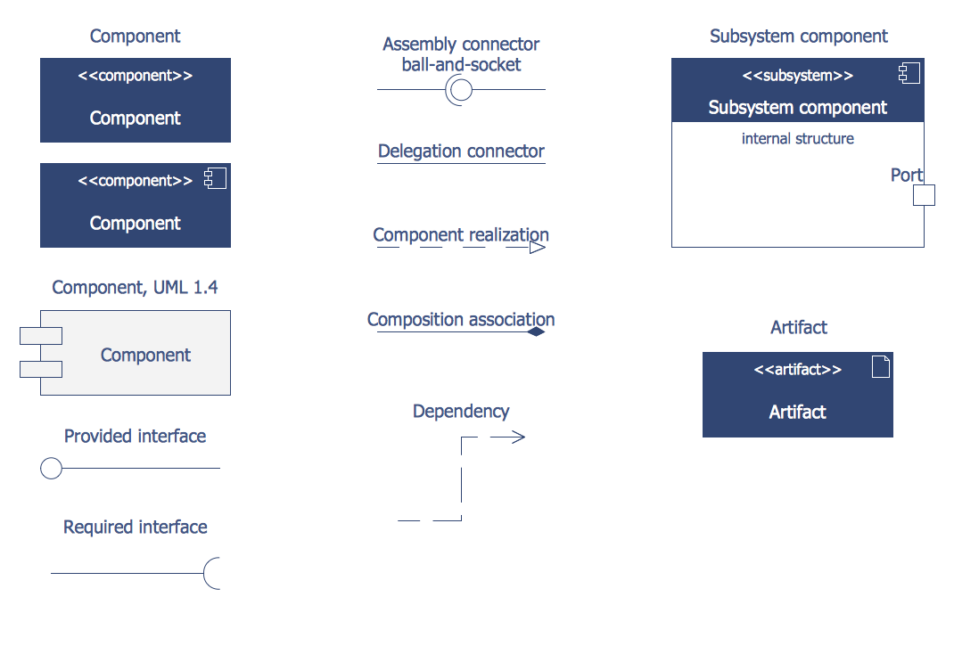
Design Elements — Bank UML Component Diagram
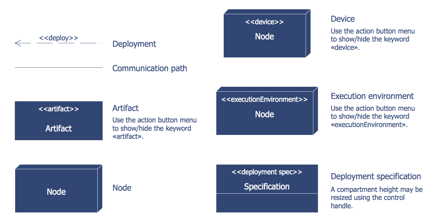
Design Elements — Bank UML Deployment Diagram
Design Elements — Bank UML Interaction Overview Diagram
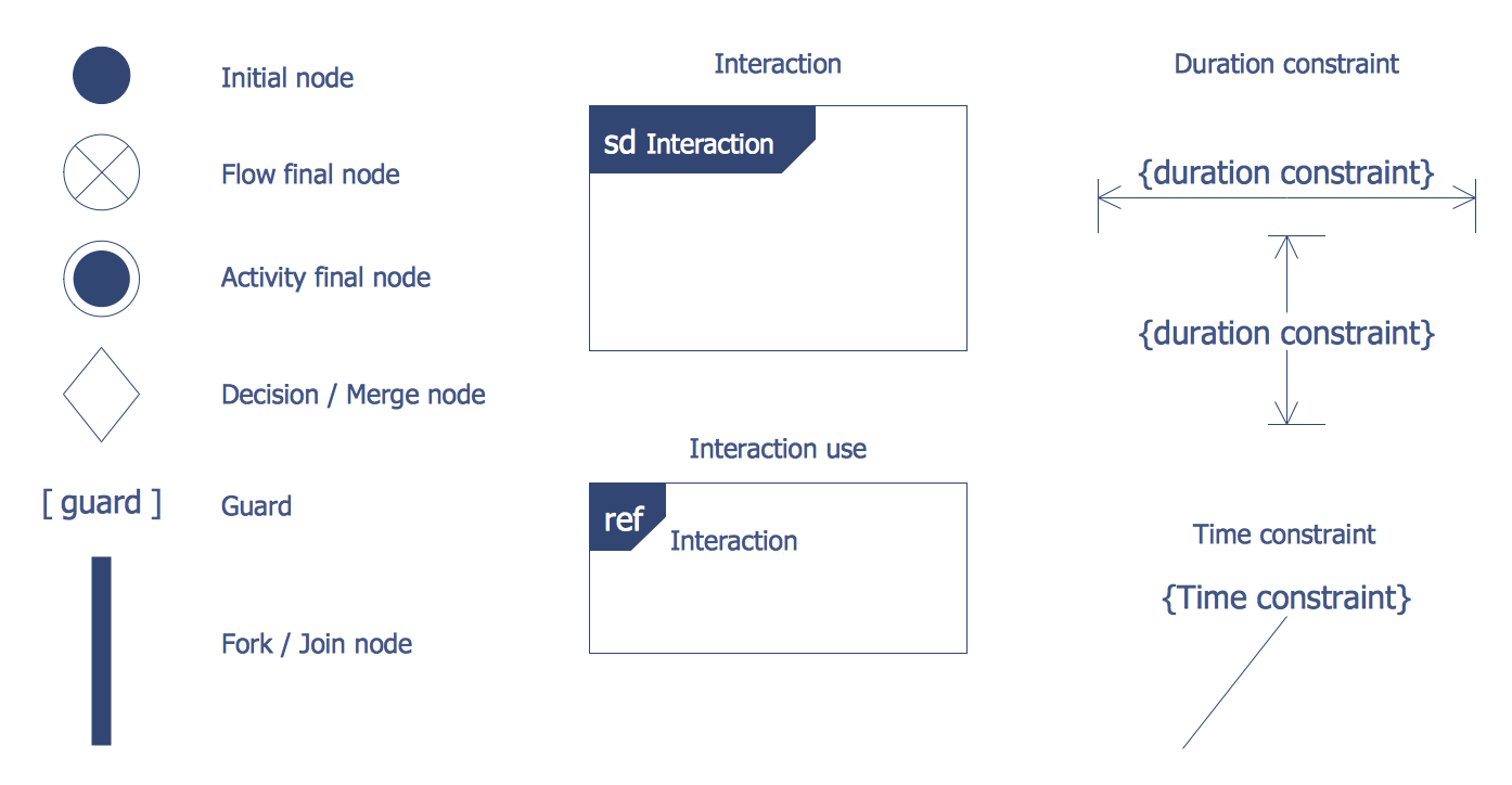
Design Elements — Bank UML Profile Diagram

Design Elements — Bank UML Sequence Diagram
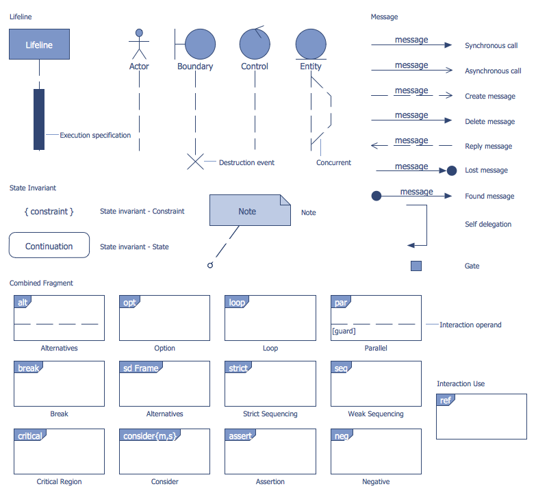
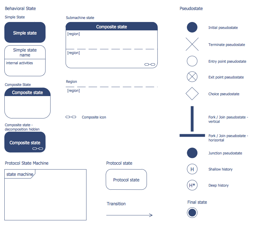
Design Elements — Bank UML State Machine Diagram
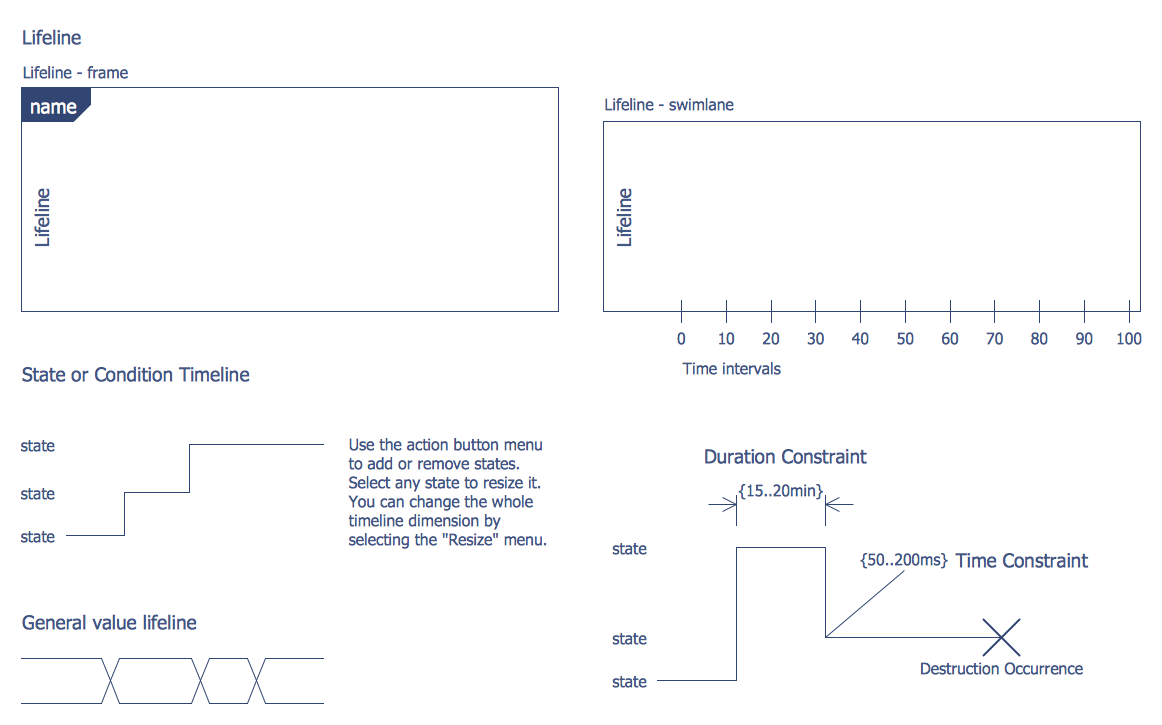
Design Elements — Bank UML Timing Diagram
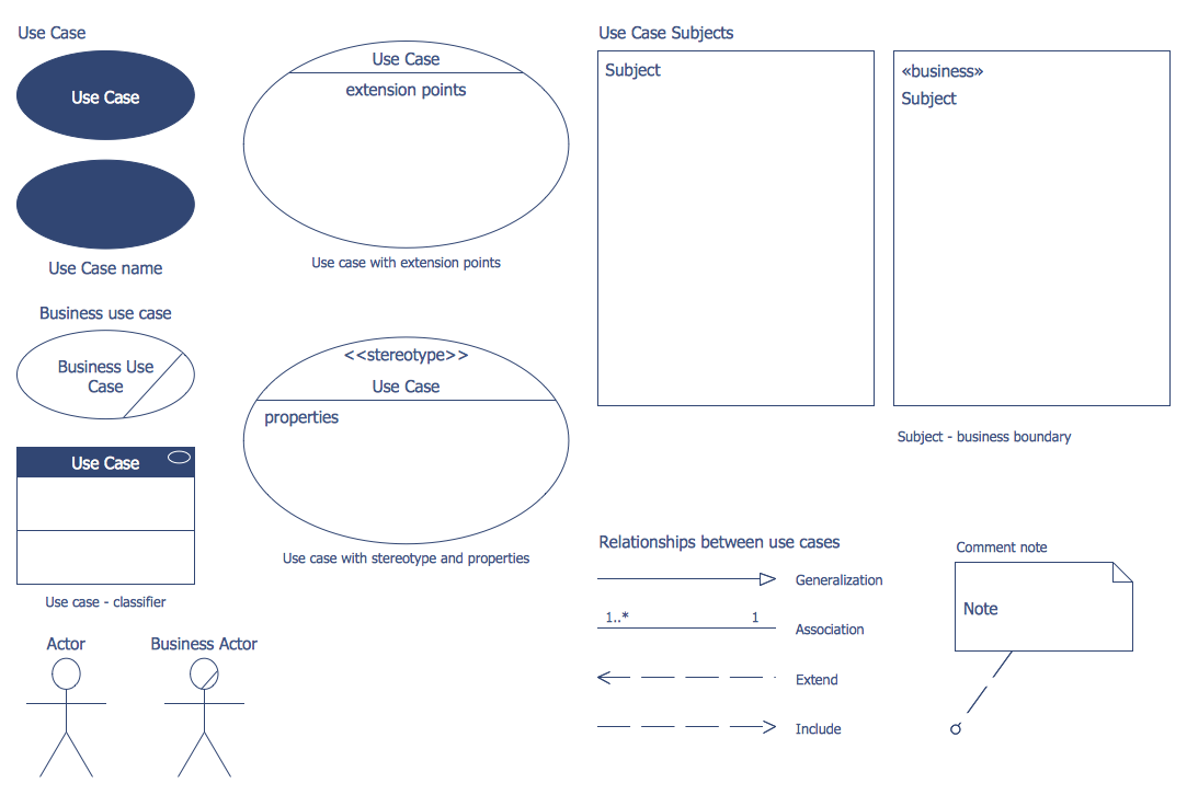
Design Elements — Bank UML Use Case Diagram
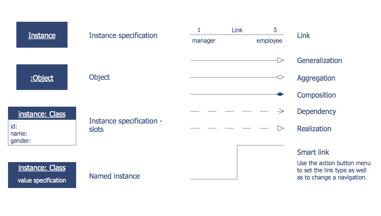
Design Elements — Bank UML Object Diagram
Related News:
New ConceptDraw Solution Park Point Solution that Supports an Extensive Array of ATM UML Diagrams and the Associated ObjectsExamples
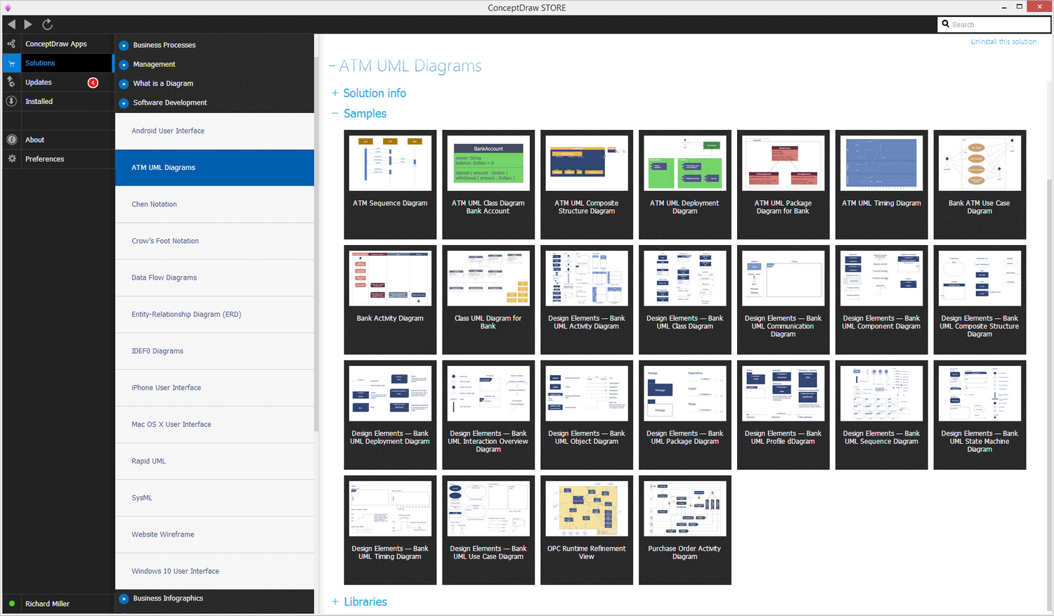
There are a few samples that you see on this page which were created in the ConceptDraw DIAGRAM application by using the ATM UML Diagrams solution. Some of the solution's capabilities as well as the professional results which you can achieve are all demonstrated here on this page.
All source documents are vector graphic documents which are always available for modifying, reviewing and/or converting to many different formats, such as MS PowerPoint, PDF file, MS Visio, and many other graphic ones from the ConceptDraw Solution Park or ConceptDraw STORE. The ATM UML Diagrams solution is available to all ConceptDraw DIAGRAM users to get installed and used while working in the ConceptDraw DIAGRAM diagramming and drawing software.
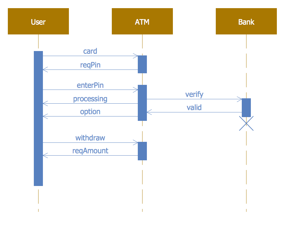
Example 1: ATM Sequence Diagram
This diagram was created in ConceptDraw DIAGRAM using the Bank UML Sequence library from the ATM UML Diagrams solution. An experienced user spent 10 minutes creating this sample.
This ATM Sequence diagram sample deconstructs the process of interaction between customer, ATM, and bank, and shows the transaction in a simple and clear manner. It was designed on the base of the "Sequence diagram" illustration from the website of the University of California Irvine (UCI) Donald Bren School of Information and Computer Sciences and webpage "Message Sequence Charts and their Ilk". Three components of the chart are represented as the rectangles — User, ATM, Bank, from them pass the timelines depicted by dotted lines. On the horizontal arrows, you can observe the processes that proceed between the user and ATM, between ATM and bank. The arrows directions show the processes directions, who realize each of them. The X symbol indicates that the component stops its existence. Using the ConceptDraw DIAGRAM software as a UML image creator, it is possible to display just one linear process or create a more complex design.
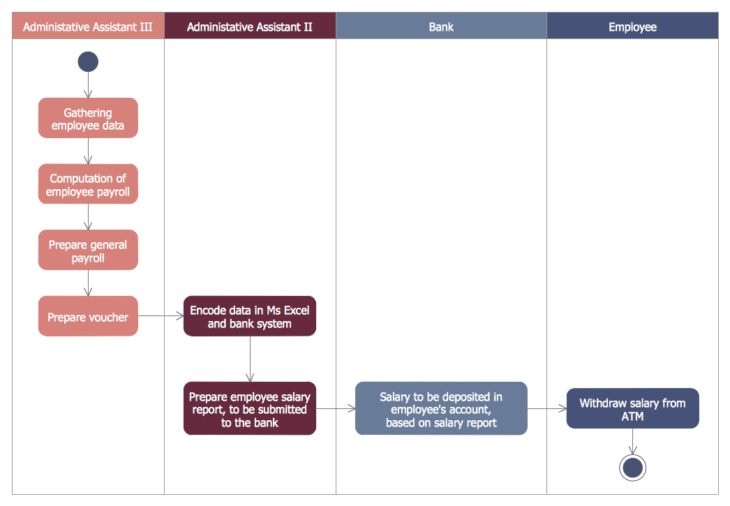
Example 2: Bank Activity Diagram
This diagram was created in ConceptDraw DIAGRAM using the Bank UML State Machine Diagram library from the ATM UML Diagrams solution. An experienced user spent 10 minutes creating this sample.
This Bank Activity diagram example is based on the illustration from the webpage "Automated payroll management system" published on the ethelmandane.wikispaces.com website. The automated payroll management system is depicted in the form of a UML Activity diagram. Today many countries and enterprises in different countries try to automate the different processes with the goal of increasing their efficiency. One of these processes is a payroll process for the workers and employees. The automated payroll system helps not only in reducing time and effort when calculating employees' salaries but also in increasing the productivity and efficiency of the whole organization. Each column includes the own steps of the process. Add the text to your design to create an information-rich drawing, that successfully combines professional UML elements and icons with written indicators. Large symbol libraries contained in the ATM UML Diagrams solution will help you create your banking system design and attractive Bank UML diagram in moments.
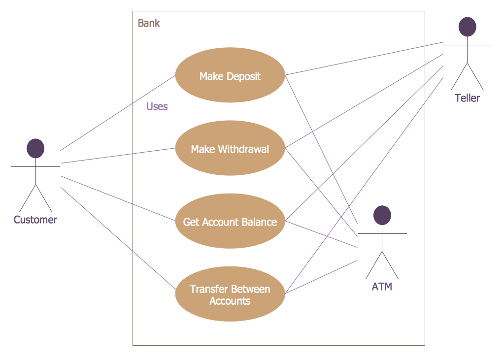
Example 3: Bank ATM Use Case Diagram
This diagram was created in ConceptDraw DIAGRAM using the Bank UML Communication Diagram library from the ATM UML Diagrams solution. An experienced user spent 10 minutes creating this sample.
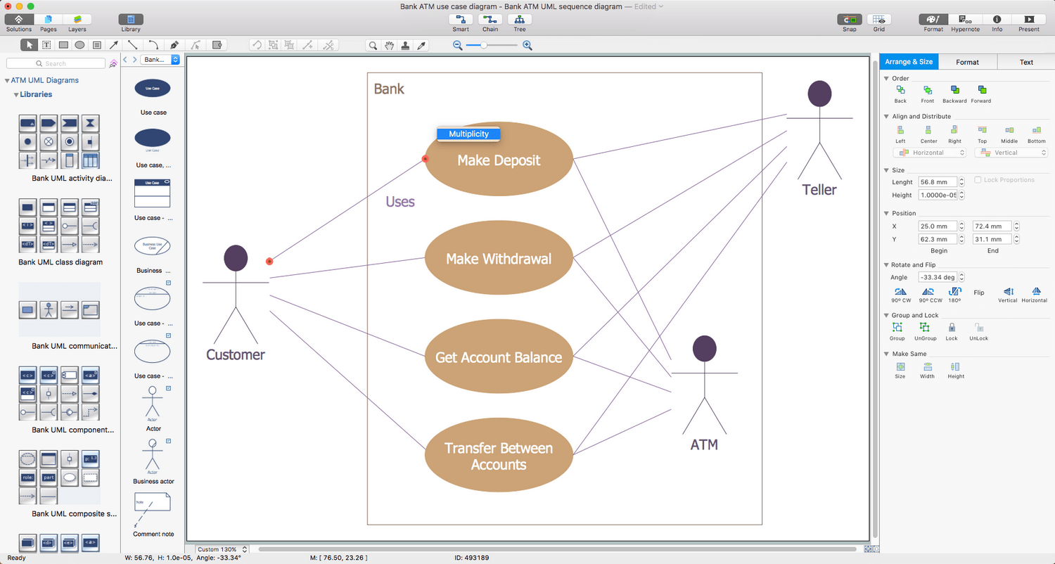
Here is represented a basic example of a bank ATM UML Activity diagram created on the base of Use Case diagram of automated teller machine published by Bruce Eckel on the website of the Computer Science and Electrical Engineering Department of the University of Maryland, Baltimore (UMBC) at the course "Thinking in Java, 2nd edition, Revision 9". The Use Case diagram is a diagram showing all possible transactions available to a user or customer and the relationships with each one. It is a simple diagram without extra details that however illustrates all main points. The customer, ATM, and teller are actors, the box represents the boundaries of your system, the use cases are represented by ellipses and contain descriptions of the work that can be performed with the system. The lines connecting the actors and the use cases represent the interactions between them. ConceptDraw DIAGRAM software provides a visual platform for displaying your ATM solutions, designing different types of UML diagrams for the banking system, including the Bank Use Case diagram, Bank Sequence diagram, etc.
Example 4: Class UML Diagram for Bank
This diagram was created in ConceptDraw DIAGRAM using the Bank UML Class Diagram library from the ATM UML Diagrams solution. An experienced user spent 15 minutes creating this sample.
This example of the ATM UML Class diagram models the bank account system that is a system of managing the financial accounts belonging to the bank customers in a bank financial institution. You can observe the classes of Bank, Contact, Address, Statement, Account, Customer, SavingAccount, FlexibleSavingAccount, and ChekingAccount with defined attributes and operations on this Bank Class diagram, as well as some determined data types: Money, InterestRate, Email, Period, PhoneNumber, and Date. The Bank class represents a physical bank, it has the name attribute and manages several accounts, contacts, and customers. The Customer class represents a real customer, which has the name and surname, the Account class represents a customer's bank account with such attributes as the balance, interestRate, and interestPeriod. The Contact class contains the phone, mobile, and email attributes, the Address class in its turn includes the information about street, house number, zip code, and city, the Statement class has data and content attributes.

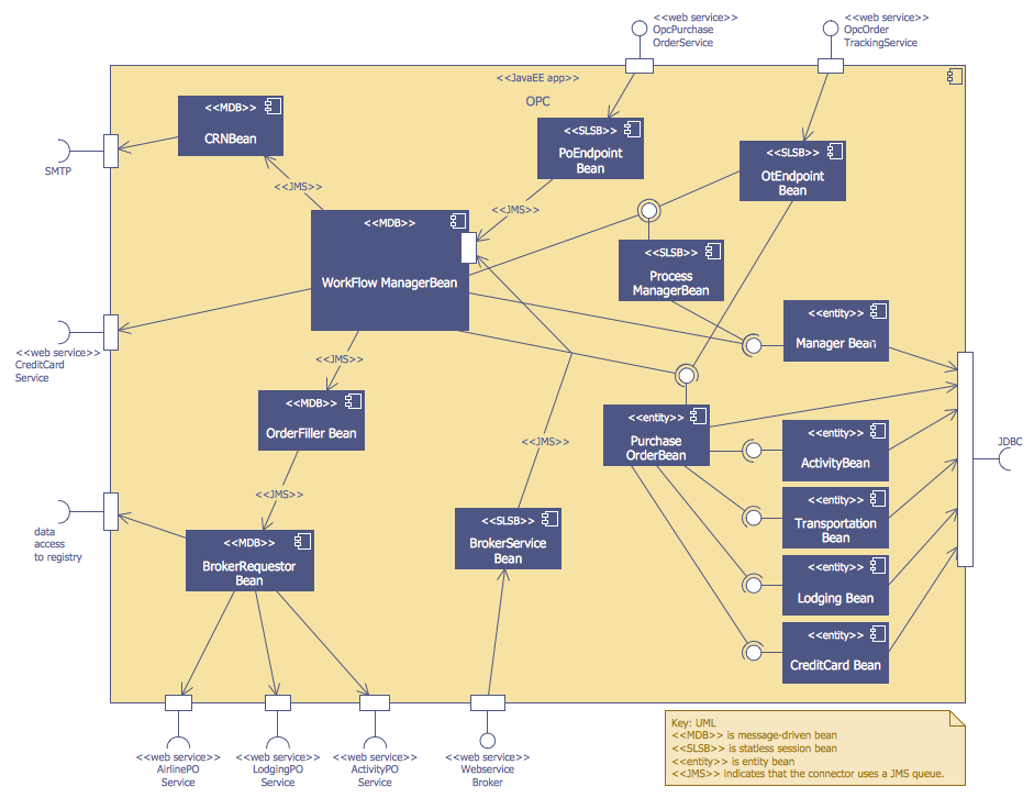
Example 5: OPC Runtime Refinement View
This diagram was created in ConceptDraw DIAGRAM using the Bank UML Component Diagram from the ATM UML Diagrams solution. An experienced user spent 20 minutes creating this sample.
This sample demonstrates the UML Sequence diagram of the order processing center (OPC). It was constructed in ConceptDraw DIAGRAM software on the base of the Sequence diagram from the software architecture documentation wiki offered by the Software Engineering Institute (SEI) of Carnegie Mellon University (CMU). The order processing is one of the key processes or work-flows in order fulfillment, it includes the picking, packing, and delivering of the items to a shipping carrier. The order processing centers, distribution centers, and shipping companies are involved in this process. The offered sample is an example that gives a small idea of how the technical and detailed drawing can be created fast, easy and professionally. You can observe a lot of components and entities in the diagram that aptly formed it. Due to the wide variety of professional elements found in the ATM UML Diagrams solution, your UML examples will be universally understood.
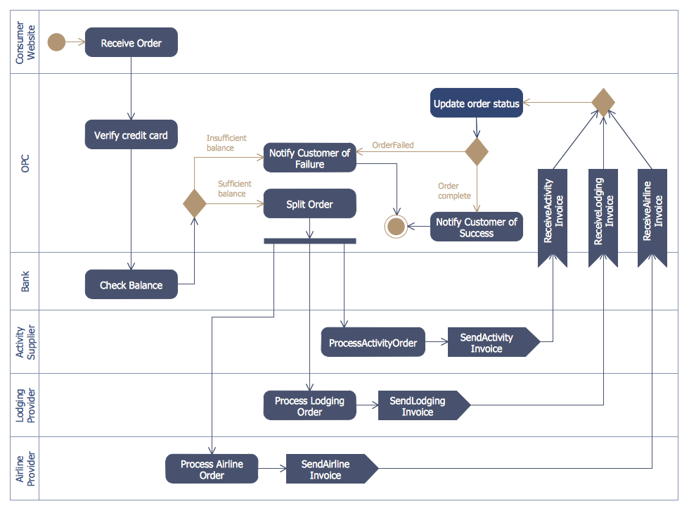
Example 6: Purchase Order Activity Diagram
This diagram was created in ConceptDraw DIAGRAM using the Bank UML Component Diagram from the ATM UML Diagrams solution. An experienced user spent 15 minutes creating this sample.
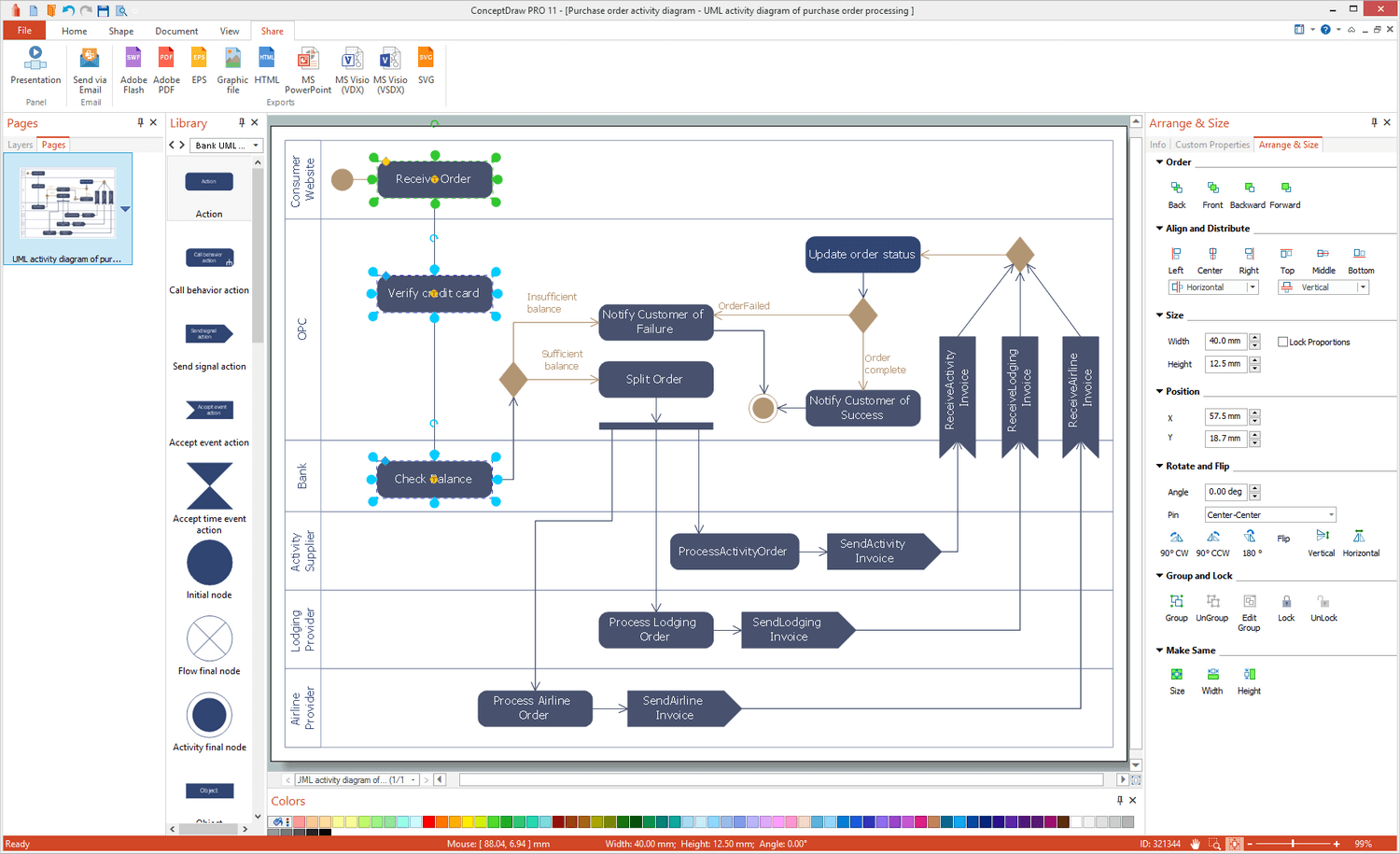
This sample represents the UML Activity diagram illustrating the purchase order processing. It was designed on the base of the Activity diagram from the software architecture documentation wiki published by the Software Engineering Institute (SEI) of Carnegie Mellon University (CMU). The purchase order (PO) is a document indicating the types, quantities, and prices for desired products or services, which is composed by a buyer and offered to a seller. This document is accepted by a seller and is used by both sides to control the purchase of the products or services. You can visually track all steps of the purchase order processing process in this diagram. Thus, the process begins by the order receiving, verification the credit card, and checking balance, also includes the chain of intermediate steps related to order splitting, sending and receiving an invoice, updating purchase status, and ends by successful order completing or notification customer about the failure.
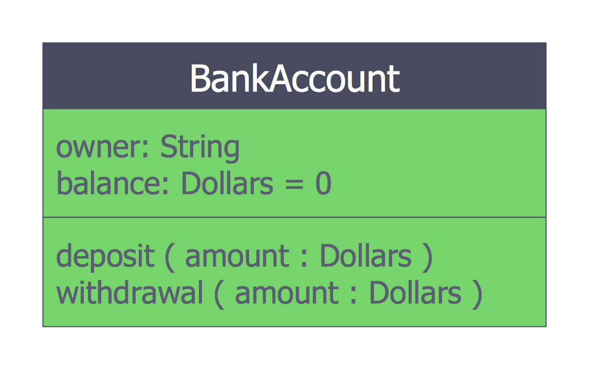
Example 7: ATM UML Class Diagram Bank Account
This diagram was created in ConceptDraw DIAGRAM using the Bank UML Component Diagram from the ATM UML Diagrams solution. An experienced user spent 5 minutes creating this sample.
A Class diagram is incredibly useful when the complex system data are presented, particularly in a hierarchical 'class' system. The actions, relationships, and dependencies are portrayed effectively, the pre-made library icons can be customized and filled with text. This bank account UML Class diagram is based on the Wikimedia Commons file "BankAccount1.svg" and represents the BankAccount class. The common attributes of any bank account include the owner's name and balance. You can deposit() money to the account and withdraw() them from it. The bank account can have a positive balance (credit) or a negative balance (debit). In this sample, you see only one class, but it can have a lot of related classes when the Class diagram for an overall bank system will be constructed. The Bank class, the Customer class can be added, the banks typically offer different types of accounts (checking and savings) that will be also represented by two child classes, etc.
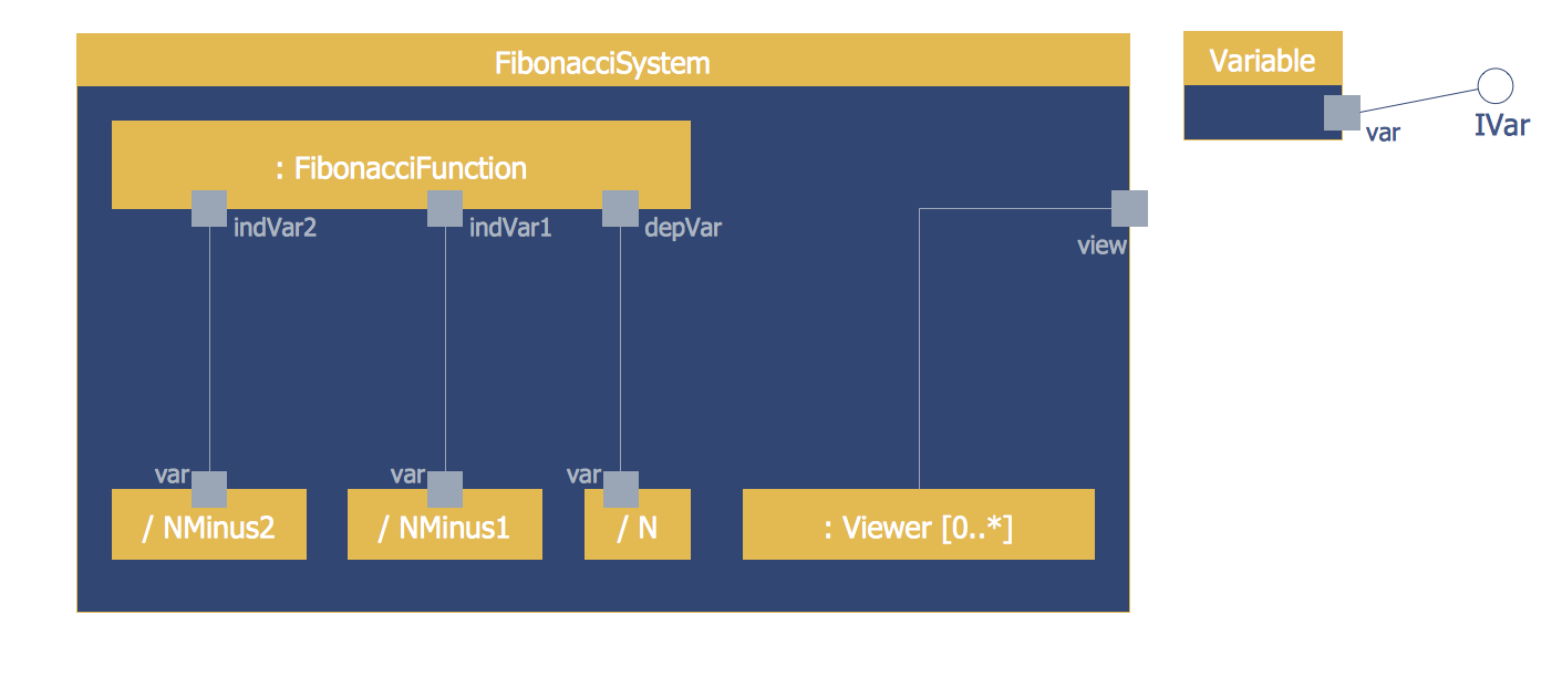
Example 8: ATM UML Composite Structure Diagram
This diagram was created in ConceptDraw DIAGRAM using the Bank UML Component Diagram from the ATM UML Diagrams solution. An experienced user spent 10 minutes creating this sample.
This ATM UML Composite Structure diagram shows the Fibonacci sequence. The Composite structure diagrams use the Unified Modeling Language (UML) to represent the groups of interconnected elements, which collaborate with each other to achieve a certain purpose, at this each of them has some defined role. This diagram specifies the instances of the 'FibonacciSystem' class and shows that they consist of several parts. The top part is a classifier 'FibonacciFunction'. Three parts are identified by their role within the instances of FibonacciSystem — NMinus2 role, NMinus1 role, and N role. At runtime, the class instances that implement these roles, provide the services specified by the IVar interface through their var ports, one of them is a Variable class. One more part is identified by its classifier Viewer, at runtime, there can be 0 or more instances of Viewer or some subclass of Viewer class. The 'view' port is a non-public port used by the instances of FibonacciSystem to access the optional instances of Viewer.
Example 9: ATM UML Deployment Diagram
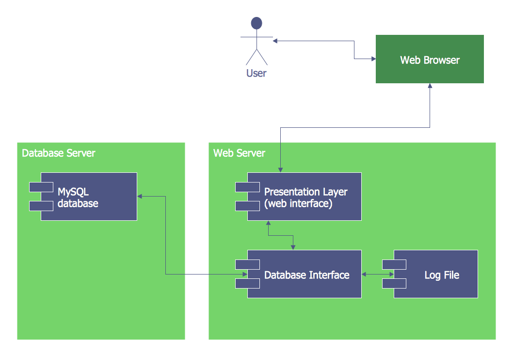
This diagram was created in ConceptDraw DIAGRAM using the Bank UML Component Diagram from the ATM UML Diagrams solution. An experienced user spent 10 minutes creating this sample.
This UML Deployment diagram is designed on the base of Wikimedia Commons file "UML Diagram Deployment.svg". It allows modeling the hardware used in system implementations, as well as the execution environments and artifacts deployed on the hardware. The Deployment diagram depicts what hardware components or nodes exist, what software components named artifacts run on each node, and also how the different parts are connected. The nodes are represented by the boxes on the Deployment diagram, the artifacts allocated to each node are depicted as rectangles at the corresponding boxes. There are three nodes on this diagram — Web Browser, Database Server, and Web Server. The actor that interacts with the Web Browser is also depicted. The modeling language, such as UML and Deployment Diagrams are widely used by software designers and programmers for making the project plans of different kinds. The diagram is simple for easy perception and colorful, so attractive for the wide auditorium.
Example 10: ATM UML Package Diagram for Bank
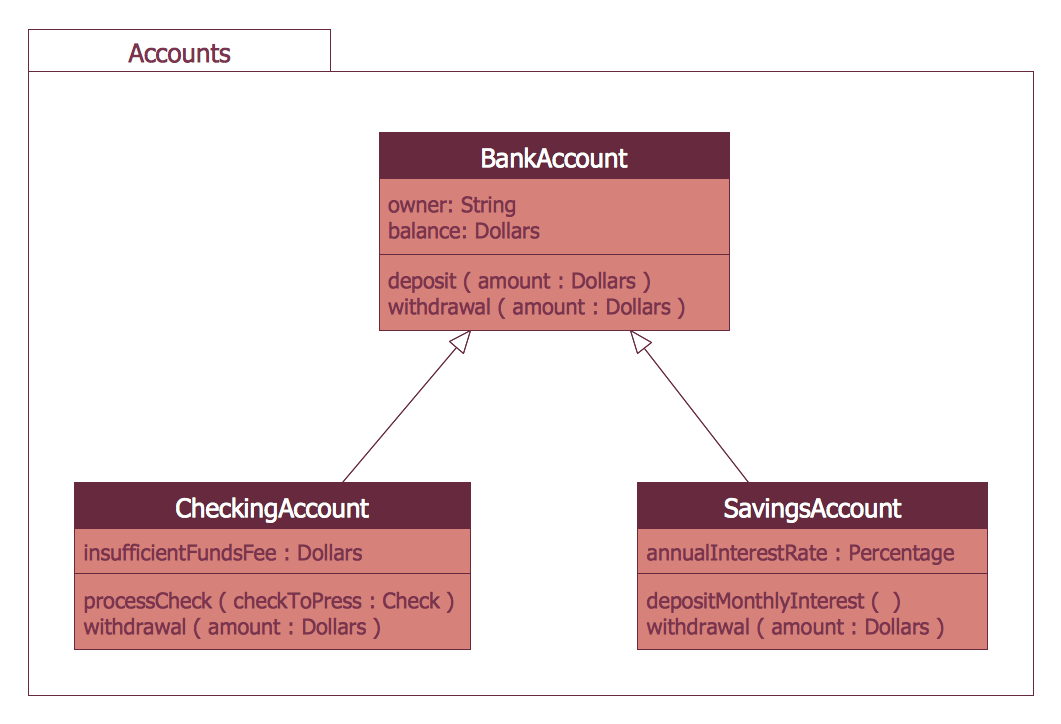
This diagram was created in ConceptDraw DIAGRAM using the Bank UML Component Diagram from the ATM UML Diagrams solution. An experienced user spent 10 minutes creating this sample.
This sample represents the bank account UML Package diagram that is based on the Wikimedia Commons file "Package diagram1.jpg". This sample illustrates one of the main concepts of the object-oriented design — the inheritance of classes. You can observe the BankAccount class and two child classes CheckingAccount and SavingsAccount that inherit the functionality of the BankAccount superclass, as well as additionally have their own new functionality. The fact of inheritance is indicated by the solid line with a closed arrow that connects each child class with the superclass. The BankAccount class has two attributes: the owner's name and balance in dollars, if desired, you can even set a default value 0 for the new account's balance. This class also has two methods deposit and withdrawal. The child classes have the insufficientFundsFee and annualInterestRate attributes correspondingly, as well as the methods processCheck and depositMonthlyInterest, and both classes inherit the withdrawal method.
Example 11: ATM UML Timing Diagram
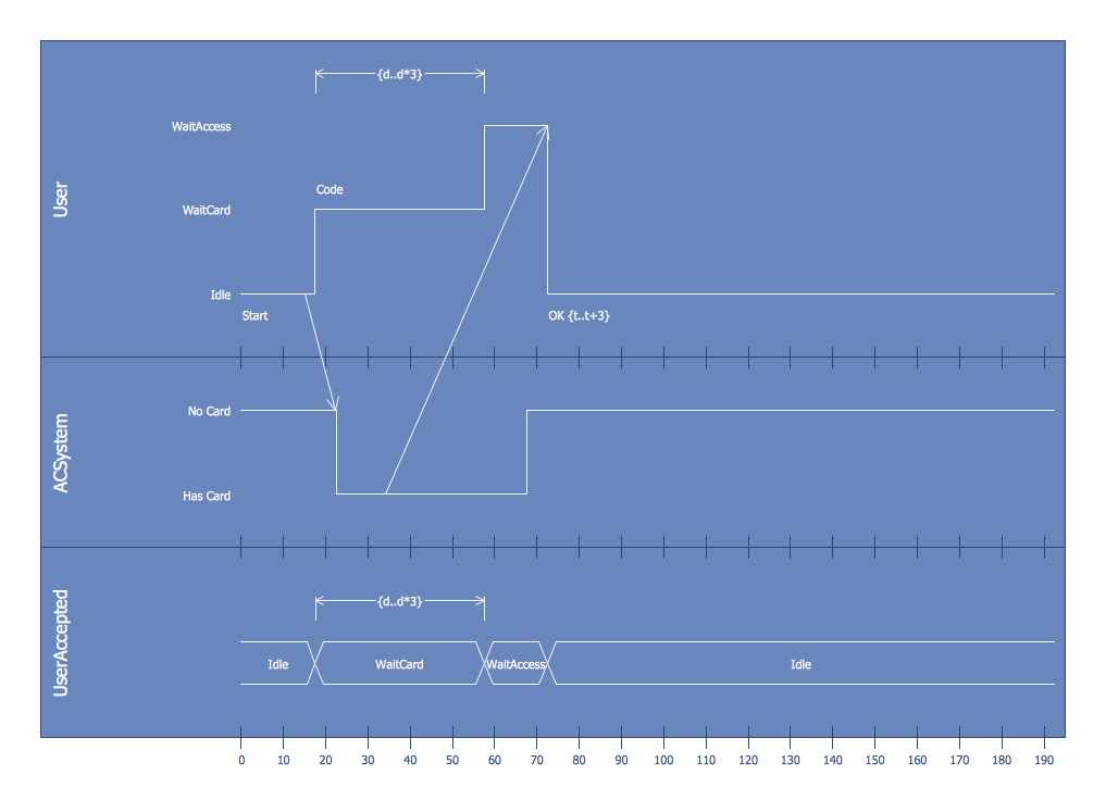
This diagram was created in ConceptDraw DIAGRAM using the Bank UML Component Diagram from the ATM UML Diagrams solution. An experienced user spent 15 minutes creating this sample.
This ATM UML Diagram sample shows the UML Timing diagram that was constructed on the base of the example from the "Determining Which UML Diagram to Use" post placed in the Architexa blog. The Timing diagrams are the special type of UML diagrams that focus on the behavior of objects over time and help one define the periods of high traffic and overloading your program. They are often used when the embedded systems are designed and allow focusing attention on time of occurrence events that cause changes in the modeled conditions. The use of the Timing diagram is the best way for the project including many objects that repeatedly change their status over time, it is perfect for illustrating all steps of this project and time periods of their execution. This Timing diagram includes three lifelines with instances User, ACSystem, and UserAccepted. You can see the horizontal scale that displays the time and the vertically depicted states.
Inside
What I Need to Get Started
After ConceptDraw DIAGRAM is installed, the ATM UML Diagrams solution can be purchased either from the Software Development area of ConceptDraw STORE itself or from our online store. Thus, you will be able to use the ATM UML Diagrams solution straight after.
How to install
First of all, make sure that both ConceptDraw STORE and ConceptDraw DIAGRAM applications are downloaded and installed on your computer. Next, install the ATM UML Diagrams solution from the ConceptDraw STORE to use it in the ConceptDraw DIAGRAM application.
Start Using
Start using the ATM UML Diagrams solution to make the professionally looking software engineering diagrams by adding the design elements taken from the stencil libraries and editing the pre-made examples that can be found there.
ATM systems modeling using UML diagram
Since their introduction in the 1960s, ATMs have become ubiquitous, providing round-the-clock access to funds in your bank. An ATM can exist in different forms - like a “hole in the wall” next to banks or shops, or as a separate unit in a restaurant or club - but the transaction process for the client remains the same in each case. They are required to insert an ATM card and enter a personal identification number (PIN), which is then verified by the bank. After approval at this stage, the client is provided with a number of banking opportunities, including cash withdrawals, balance requests and money transfers. The card is returned to the user after completion of all transactions.
Before writing program code for an ATM or any other system project, it is necessary to create a visual representation of any object-oriented processes. This is achieved most efficiently by creating a UML diagram using object-oriented modeling. UML works as a general-purpose modeling language for software developers or system analysts, offering a number of different diagram styles that can be used to visually portray all aspects of a software system.
For an ATM, there are a number of different processes, transactions, and interactions that can be displayed in this way using UML diagrams, or different representations of the same process can be displayed using different styles of the modeling language. In general terms, UML diagrams are divided into two types - structural diagrams (static modeling) and behavioral diagrams (dynamic modeling). In the case of an ATM, this allows you to show the system architecture and the interaction, the relationships between objects and entities (for example, a client and a bank) or changes in these objects depending on the transaction (for example, an incorrect PIN code has been entered).
You will also need to decide whether your diagram uses the Object Oriented Analysis (OOA) or Object Oriented Design (OOD) approach. The difference is that the goal of the first is to create a model of the functional system requirements, which does not depend on implementation restrictions. Using the latter, a developer applies implementation constraints to a conceptual model created in an object-oriented analysis.
OOA using UML diagrams
Types of UML structure diagram:
- Use case diagram — A common method when object-oriented modeling is to present a system in the form of a use case (Fig 1.), which define interactions between the user (or 'actor') and a system, to achieve a specific goal.

Fig 1. A simple use case diagram
- Class diagram — a class diagram allows you to group together certain transactions and objects into distinct 'classes', and display there attributes and possible interactions. You might define one class of an ATM system as 'Customer', another as 'Account', and the diagram shows the attributes of each and any available actions (Fig 2.).

Fig 2. Class UML diagram for bank
- Composite structure diagram — this form of diagram can be used to map physical components of a structure and there collaboration with each other. A composite structure diagram of an ATM machine would show elements such as the keypad, receipt printer, processor and modem, and how they interact (Fig 3.).

Fig 3. ATM UML Composite structure diagram
- Object diagrams — they show a 'snapshot' of a system, by modeling its objects and their relationships at a specific point in time. Each object represents an instance of a class from a class diagram, and several objects may be created from one class. For an ATM system, an object diagram could show several distinct Account objects side by side, illustrating that they are all part of the bank’s account database.
- Package diagram — 'package' is a term for when classes or objects are grouped together, and the diagram shows their hierarchical structure (Fig 4.).

Fig 4. ATM UML Package diagram for bank
Types of UML behavioral diagrams:
- State machine diagram — this describes the possible 'state' of a system dependent on inputs and interactions. A diagram for an ATM could show all possible states, active, idle, out of service, and what input is required to reach each one.
- Activity diagram — describes a linear, step-by-step process, and the actions and decisions available within it. It isolates a particular workflow, such as the steps needed for a successful customer purchase transaction (Fig 5.)

Fig 5. Activity diagram for a customer purchase order
- Interaction diagrams — these are a subset of behavioral diagrams that include sequence, timing, communication and interactive overview diagrams. In a general sense, they focus on the interaction between objects and classes, and how they communicate with each other.
For instance, and ATM sequence diagram will show object interactions arranged in chronological sequence (Fig 6.). A timing diagram will model the time constraints imposed on state changes. An interactive overview diagram can combine elements from other types of diagram (e.g. activity, sequence) to present a summary of control flow.

Fig 6. A sequence diagram showing the order of interaction between user, ATM, and bank
OOD using UML diagrams
Object-oriented design works in tandem with object-oriented analysis — while OOA documents the ideal form of a process or system, and its objects or interactions, OOD works on defining exactly what those objects are, and what elements are necessary for the process to work effectively. This can be done using the deployment and component forms of UML diagrams.
- Deployment diagram. In the case of an ATM machine, a deployment diagram might show the runtime requirements of the system, memory requirements, or other devices the system needs to execute (Fig 7.).

Fig 7. ATM UML Development diagram for bank
- Component diagram. A component diagram would show the particular elements that make up an object — so perhaps the physical components of an ATM machine, which itself can be a single element on an activity diagram, use case diagram etc (Fig 8.).

Fig 8. OPC Runtime Refinement View
Even in the case of a specialist subject such as ATM system modeling, it is possible to see the wide range of applications for UML diagrams and object-oriented modeling methods. ConceptDraw DIAGRAM diagramming software, enhanced and expanded with the ATM UML Diagrams solution, offers the full range of icons, templates and design elements needed to faithfully represent ATM and banking information system architecture using UML standards.
The ATM UML Diagrams solution is useful for beginner and advanced users alike — samples are provided to help you get started, and there is a wealth of tutorial material on the ConceptDraw website in the shape of videos and user guides. More experienced users will appreciate a full range of vector stencil libraries and ConceptDraw DIAGRAM 's powerful software, that allows you to create your ATM UML diagram in a matter of moments.


