Accounting Flowchart Symbols

Gane Sarson Diagram

How To use House Electrical Plan Software


Electrical Symbols — Thermo

Electrical Symbols — Electron Tubes

Process Flow Diagram Symbols

Total Quality Management Value

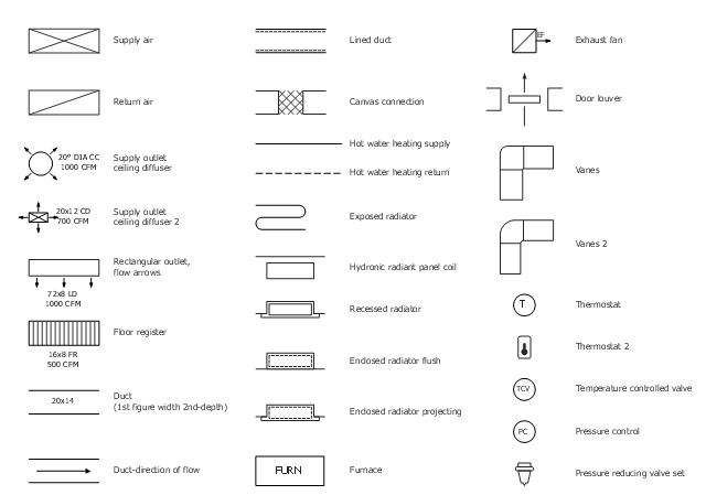
The vector stencil library "HVAC air conditioning" contains 27 air conditioning icons.
Use it for drawing HVAC system diagrams, heating, ventilation, air conditioning, refrigeration, automated building control, and environmental control design floor
plans and equipment layouts.
"Air conditioning (often referred to as AC, A/ C, or air con) is the process of removing heat and moisture from the interior of an occupied space, to improve the comfort of occupants. ...
Air conditioners often use a fan to distribute the conditioned air to an occupied space such as a building or a car to improve thermal comfort and indoor air quality. Electric refrigerant-based AC units range from small units that can cool a small bedroom, which can be carried by a single adult, to massive units installed on the roof of office towers that can cool an entire building." [Air conditioning. Wikipedia]
The air conditioning symbols example "Design elements - HVAC air conditioning" is included in HVAC Plans solution from the Building Plans area of ConceptDraw Solution Park.
Context Diagram Template

This template shows the Context Diagram. It was created in ConceptDraw DIAGRAM diagramming and vector drawing software using the Block Diagrams Solution from the “Diagrams” area of ConceptDraw Solution Park. The context diagram graphically identifies the system. external factors, and relations between them. It’s a high level view of the system. The context diagrams are widely used in software engineering and systems engineering for designing the systems that process the information.
Competitor Analysis

Cross-Functional Flowchart


 Flowcharts
The Flowcharts solution for ConceptDraw DIAGRAM is a comprehensive set of examples and samples in several varied color themes for professionals that need to represent graphically a process. Solution value is added by the basic flow chart template and shapes' libraries of flowchart notation. ConceptDraw DIAGRAM flow chart creator lets one depict the processes of any complexity and length, as well as design the Flowchart either vertically or horizontally.
The vector stencils library "Cisco network topology" contains 89 symbols of Cisco network devices and design elements for drawing computer network topology diagrams.
"There are two basic categories of network topologies:
(1) Physical topologies,
(2) Logical topologies.
The shape of the cabling layout used to link devices is called the physical topology of the network. This refers to the layout of cabling, the locations of nodes, and the interconnections between the nodes and the cabling. The physical topology of a network is determined by the capabilities of the network access devices and media, the level of control or fault tolerance desired, and the cost associated with cabling or telecommunications circuits.
The logical topology in contrast, is the way that the signals act on the network media, or the way that the data passes through the network from one device to the next without regard to the physical interconnection of the devices." [Network topology. Wikipedia]
The symbols example "Cisco network topology - Vector stencils library" was created using the ConceptDraw PRO diagramming and vector drawing software extended with the Cisco Network Diagrams solution from the Computer and Networks area of ConceptDraw Solution Park.
www.conceptdraw.com/ solution-park/ computer-networks-cisco
Router

Broadband router

Router firewall

Wireless router

Workgroup switch

ATM switch

ISDN switch

Multilayer switch

Protocol translator

Communications server

Transpath

Bridge

Terminal server

Route switch processor

Content engine (cache director)
-cisco-network-topology---vector-stencils-library.png--diagram-flowchart-example.png)
Management engine (ME 1100)
-cisco-network-topology---vector-stencils-library.png--diagram-flowchart-example.png)
Switch processor

ITP

Voice gateway

BBSM

ATA

SIP Proxy server

NetRanger

Cisco 1000

IP

System controller

ACE

Directory server

ADM

Cisco Unity Express

Unity server

Cisco security

CallManager

DSLAM

H.323

CDM (Content Distribution Manager)
-cisco-network-topology---vector-stencils-library.png--diagram-flowchart-example.png)
ICM

Access point

Wireless bridge

Wireless connectivity

Guard

Mobile access router

Carrier Routing System (CRS)
-cisco-network-topology---vector-stencils-library.png--diagram-flowchart-example.png)
Vault

Workstation

PC

Macintosh

Cloud, gold

Cloud, white

Cloud, standard color

Cisco security management

PBX

DPT

Government building

Headquarters, blue

Router in building

Man

Woman

Workgroup switch, subdued

Router, subdued

File server

Firewall, horizontal

Firewall, vertical

Firewall, vertical, subdued

Lock

Key

Lock and key

Car

Truck

File cabinet

Breakout box

Breakout box, blue

Host

Relational database

Modem

BBS (Bulletin Board System)
-cisco-network-topology---vector-stencils-library.png--diagram-flowchart-example.png)
Satellite

Satellite dish

UPS

RPS

MAU

PAD

PAD X.28

Diskette

Contact center

Page icon
Antenna

Antenna, blue

Radio tower

BPR Diagram. Business Process Reengineering Example

Technical Drawing Software

CAD Drawing Software for Making Mechanic Diagram and Electrical Diagram Architectural Designs

Contoh Flowchart

Directions Maps

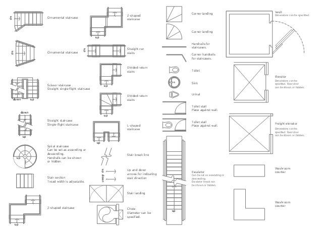
The design elements library Building core contains 80 symbols of stairs, elevators, escalators, restroom fixtures, and a safe.
Use the shapes library Building core to draw the structural diagrams, bathroom layouts, building automation, architectural drawings, and riser diagrams, as well as space plans, store and shopping mall plans, and facility planning, plant layouts using the ConceptDraw PRO diagramming and vector drawing software.
"In architecture and building engineering, a floor plan otherwise known as a Scottish plan is a drawing to scale, showing a view from above, of the relationships between rooms, spaces and other physical features at one level of a structure.
The term may be used in general to describe any drawing showing the physical layout of objects.
A floor plan could show:
Interior walls and hallways;
Restrooms;
Windows and doors;
Appliances such as stoves, refrigerators, water heater etc.;
Interior features such as fireplaces, saunas and whirlpools;
The use of all rooms shall be indicated." [Floor plan. Wikipedia]
The vector stencils library Building core is provided by the Floor Plans solution from the Building Plans area of ConceptDraw Solution Park.
 Chemical and Process Engineering
This chemical engineering solution extends ConceptDraw DIAGRAM.9.5 (or later) with process flow diagram symbols, samples, process diagrams templates and libraries of design elements for creating process and instrumentation diagrams, block flow diagrams (BFD
- Basic Flowchart Symbols and Meaning | Process Flowchart | Design ...
- Plumbing Symbols Definition
- Flowchart Definition | Business Report Pie. Pie Chart Examples ...
- Mechanical Drawing Symbols | Design elements - Fluid power ...
- Single Line Diagram Of Hvac Water Cooler System
- Design elements - Alarm and access control | Electrical Symbols ...
- Air Conditioning Switch Symbol
- Door Access Control System Symbols
- Symbol Water Pump
- Design elements - Alarm and access control | Design elements ...
- HVAC Plans | RCP - HVAC layout | How to Create a HVAC Plan | Hvac
- Design elements - Alarm and access control | Design elements ...
- Alarm Sensor Symbol On Plan
- Design elements - Alarm and access control | Security system floor ...
- Design elements - HVAC controls | Design elements - Alarm and ...
- HVAC Plans | Block diagram - Automotive HVAC system | HVAC ...
- Floor Plan Smoke Detector Symbol
- Design elements - HVAC controls | Design elements - Events BPMN ...
- Design elements - Alarm and access control | How To use House ...
- Electrical Symbols — Switches and Relays | Design elements ...