Cloud Computing
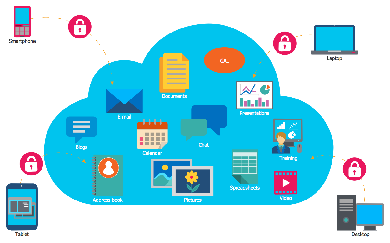
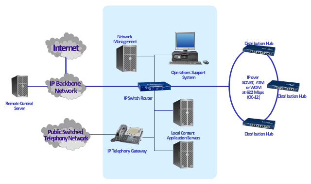
The Cloud Computing is the use of the software and hardware that includes the great number of computers connected over the communication network such as the Internet. The Cloud name comes from the usage the cloud symbol on the system diagrams as the abstraction for the complex network infrastructure. This term is used as a marketing metaphor for the Internet.This example was created in ConceptDraw PRO using the Computer and Networks Area of ConceptDraw Solution Park and shows the Cloud Computing.
Cloud Computing Architecture Diagrams
For documenting the Cloud Computing Architecture with a goal to facilitate the communication between stakeholders are successfully used the Cloud Computing Architecture diagrams. It is convenient and easy to draw various Cloud Computing Architecture diagrams in ConceptDraw PRO software with help of tools of the Cloud Computing Diagrams Solution from the Computer and Networks Area of ConceptDraw Solution Park.The vector stencils library "Computer network" contains 51 symbols of computer network devices and equipment for drawing computer network diagrams.
"Network Mapping Software.
A number of software tools exist to design computer network diagrams / or generate visual maps of networks, servers, storage, services, data centers, and other peripherals. Broadly, there are two types of software tools - those that help create diagrams manually and those that generate them using automated / semi-automated approaches.
Type of Software.
(1) Manual - allows users to design and draw logical and physical topology diagrams by manually placing icons and connections.
(2) Automated - generate topology diagrams / maps by traversing the network and automatically discovering resident devices or by importing network data." [Comparison of network diagram software. Wikipedia]
ConceptDraw PRO is the software for manual design of computer network diagrams. The solutions of the Computer and Networks area in ConceptDraw Solution Park extend ConceptDraw PRO with vector stencils libraries, templates and examples for creating the computer network diagrams.
The symbols example "Computer network - Vector stencils library" was created using the ConceptDraw PRO diagramming and vector drawing software extended with the Computer and Networks solution from the Computer and Networks area of ConceptDraw Solution Park.
www.conceptdraw.com/ solution-park/ computer-and-networks
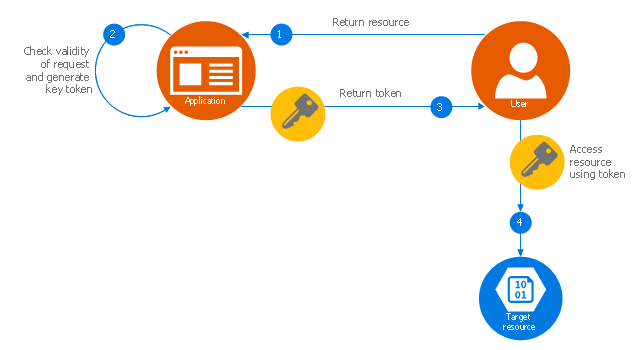
This Azure cloud architecture pattern diagram template was created on the base of figure in the article "Valet Key Pattern" from the Microsoft Developer Network (MSDN) website.
"Valet Key Pattern.
Use a token or key that provides clients with restricted direct access to a specific resource or service in order to offload data transfer operations from the application code. This pattern is particularly useful in applications that use cloud-hosted storage systems or queues, and can minimize cost and maximize scalability and performance. ...
Client programs and web browsers often need to read and write files or data streams to and from an application’s storage. ...
Data stores have the capability to handle upload and download of data directly, without requiring the application to perform any processing to move this data, but this typically requires the client to have access to the security credentials for the store.
... applications must be able to securely control access to data in a granular way, but still reduce the load on the server by setting up this connection and then allowing the client to communicate directly with the data store to perform the required read or write operations. ...
To resolve the problem of controlling access to a data store where the store itself cannot manage authentication and authorization of clients, one typical solution is to restrict access to the data store’s public connection and provide the client with a key or token that the data store itself can validate.
This key or token is usually referred to as a valet key. It provides time-limited access to specific resources and allows only predefined operations such as reading and writing to storage or queues, or uploading and downloading in a web browser. Applications can create and issue valet keys to client devices and web browsers quickly and easily, allowing clients to perform the required operations without requiring the application to directly handle the data transfer. This removes the processing overhead, and the consequent impact on performance and scalability, from the application and the server." [msdn.microsoft.com/ ru-RU/ library/ dn568102.aspx]
The Azure cloud system architecture diagram template "Valet key pattern" for the ConceptDraw PRO diagramming and vector drawing software is included in the Azure Architecture solutin from the Computer and Networks area of ConceptDraw Solution Park.
This vector stencils library contains 184 round icons.
Use it to design cloud computing infographics and diagrams with ConceptDraw PRO software.
"Though service-oriented architecture advocates "everything as a service" (with the acronyms EaaS or XaaS or simply aas), cloud-computing providers offer their "services" according to different models, which happen to form a stack: infrastructure-, platform- and software-as-a-service.
Infrastructure as a service (IaaS)
In the most basic cloud-service model ... providers of IaaS offer computers — physical or (more often) virtual machines — and other resources. IaaS refers to online services that abstract the user from the details of infrastructure like physical computing resources, location, data partitioning, scaling, security, backup etc.
Platform as a service (PaaS)
PaaS vendors offer a development environment to application developers. The provider typically develops toolkit and standards for development and channels for distribution and payment. In the PaaS models, cloud providers deliver a computing platform, typically including operating system, programming-language execution environment, database, and web server. Application developers can develop and run their software solutions on a cloud platform without the cost and complexity of buying and managing the underlying hardware and software layers.
Software as a service (SaaS)
In the software as a service (SaaS) model, users gain access to application software and databases. Cloud providers manage the infrastructure and platforms that run the applications. SaaS is sometimes referred to as "on-demand software" and is usually priced on a pay-per-use basis or using a subscription fee.
In the SaaS model, cloud providers install and operate application software in the cloud and cloud users access the software from cloud clients. Cloud users do not manage the cloud infrastructure and platform where the application runs. This eliminates the need to install and run the application on the cloud user's own computers, which simplifies maintenance and support. Cloud applications differ from other applications in their scalability — which can be achieved by cloning tasks onto multiple virtual machines at run-time to meet changing work demand." [Cloud computing. Wikipedia]
The vector stencils library "Cloud round icons" is included in the Cloud Computing Diagrams solution from the Computer and Networks area of ConceptDraw Solution Park.
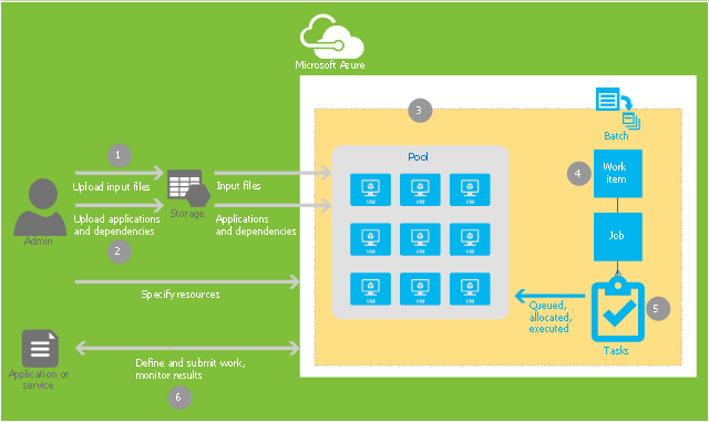
This example of cloud computing system architecture diagram was created on base of the figure "Workflow to distribute workitems to pooled VMs" in the article "Azure Batch technical overview" from the Microsoft Azure website.
"Workitems workflow.
Figure 4 shows a you how to submit an application to a pool where it's distributed for processing. This uses the Batch API. ...
1. Upload input files (such as source data or images) required for a job to an Azure storage account. These files must be in the storage account so that the Batch service can access them. The Batch service loads them onto a TVM when the task runs.
2. Upload the dependent binary files to the storage account. The binary files include the program that is run by the task and the dependent assemblies. These files must also be accessed from storage and are loaded onto the TVM.
3. Create a pool of TVMs, specifying the size of the TVMs in the pool, the OS they run, and other properties. When a task runs, it is assigned a TVM from this pool.
4. Create a workitem. A job will be automatically created when you create a workitem. A workitem enables you to manage a job of tasks.
5. Add tasks to the job. Each task uses the program that you uploaded to process information from a file you uploaded.
6. Run the application and monitor the results of the output." [azure.microsoft.com/ en-us/ documentation/ articles/ batch-technical-overview/ ]
The diagram example "Workitems workflow diagram" was created using ConceptDraw PRO diagramming and vector drawing software extended with the Azure Architecture solution from the Computer and Networks area of ConceptDraw Solution Park.
Azure Storage
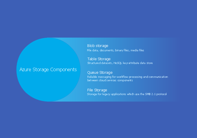
Data storage is a fundamental aspect of the cloud platform. Microsoft offers scalable, durable and elastic cloud Azure Storage which can be available from any type of application whether it’s running in the cloud and anywhere in the world.ConceptDraw PRO diagramming and vector drawing software extended with Azure Architecture Solution from the Computer and Networks area of ConceptDraw Solution Park provides a lot of useful tools which give you the possibility effectively illustrate Microsoft Azure cloud system, Azure services, Azure storage and its components.
 AWS Architecture Diagrams
The flexible AWS cloud solutions will help you to create reliable applications with a high level of scaling in the AWS cloud, to run your applications and accelerate their work on the level of security. Besides AWS resources are available worldwide and yo
The vector stencils library "AWS simple icons v2.0" contains 94 symbol icons of Amazon Web Services (AWS) elements for drawing AWS cloud architecture diagrams.
"Amazon Web Services offers a broad set of global compute, storage, database, analytics, application, and deployment services that help organizations move faster, lower IT costs, and scale applications. These services are trusted by the largest enterprises and the hottest start-ups to power a wide variety of workloads including: web and mobile applications, data processing and warehousing, storage, archive, and many others." [aws.amazon.com/ products/ ]
The symbols example "AWS simple icons v2.0 - Vector stencils library" was created using the ConceptDraw PRO diagramming and vector drawing software extended with the AWS Architecture Diagrams solution from the Computer and Networks area of ConceptDraw Solution Park.
www.conceptdraw.com/ solution-park/ computer-networks-aws
"A cable television headend is a master facility for receiving television signals for processing and distribution over a CATV system. The headend facility is normally unstaffed and surrounded by some type of security fencing and is typically a building or large shed housing electronic equipment used to receive and re-transmit video over the local cable infrastructure. One can also find head ends in power line communication (PLC) substations and Internet communications networks." [Cable television headend. Wikipedia]
This regional cable head-end diagram example was created using the ConceptDraw PRO diagramming and vector drawing software extended with the Computer and Networks solution from the Computer and Networks area of ConceptDraw Solution Park.
This regional cable head-end diagram example was created using the ConceptDraw PRO diagramming and vector drawing software extended with the Computer and Networks solution from the Computer and Networks area of ConceptDraw Solution Park.
This work flow chart sample was redesigned from the picture "Weather Forecast" from the article "Simulation Workflows".
[iaas.uni-stuttgart.de/ forschung/ projects/ simtech/ sim-workflows.php]
"(1) The weather is predicted for a particular geological area. Hence, the workflow is fed with a model of the geophysical environment of ground, air and water for a requested area.
(2) Over a specified period of time (e.g. 6 hours) several different variables are measured and observed. Ground stations, ships, airplanes, weather balloons, satellites and buoys measure the air pressure, air/ water temperature, wind velocity, air humidity, vertical temperature profiles, cloud velocity, rain fall, and more.
(3) This data needs to be collected from the different sources and stored for later access.
(4) The collected data is analyzed and transformed into a common format (e.g. Fahrenheit to Celsius scale). The normalized values are used to create the current state of the atmosphere.
(5) Then, a numerical weather forecast is made based on mathematical-physical models (e.g. GFS - Global Forecast System, UKMO - United Kingdom MOdel, GME - global model of Deutscher Wetterdienst). The environmental area needs to be discretized beforehand using grid cells. The physical parameters measured in Step 2 are exposed in 3D space as timely function. This leads to a system of partial differential equations reflecting the physical relations that is solved numerically.
(6) The results of the numerical models are complemented with a statistical interpretation (e.g. with MOS - Model-Output-Statistics). That means the forecast result of the numerical models is compared to statistical weather data. Known forecast failures are corrected.
(7) The numerical post-processing is done with DMO (Direct Model Output): the numerical results are interpolated for specific geological locations.
(8) Additionally, a statistical post-processing step removes failures of measuring devices (e.g. using KALMAN filters).
(9) The statistical interpretation and the numerical results are then observed and interpreted by meteorologists based on their subjective experiences.
(10) Finally, the weather forecast is visualized and presented to interested people." [iaas.uni-stuttgart.de/ forschung/ projects/ simtech/ sim-workflows.php]
The example "Workflow diagram - Weather forecast" was drawn using the ConceptDraw PRO diagramming and vector drawing software extended with the Workflow Diagrams solution from the Business Processes area of ConceptDraw Solution Park.
 Event-driven Process Chain (EPC) Diagrams
Event-driven Process Chain (EPC) Diagram is a type of flowchart widely used for modeling in business engineering and reengineering, business process improvement, and analysis. EPC method was developed within the Architecture of Integrated Information Systems (ARIS) framework.
 Value Stream Mapping
Value stream mapping solution extends ConceptDraw PRO software with templates, samples and vector stencils for drawing the Value Stream Maps (VSM) in lean manufacturing practice.
HelpDesk
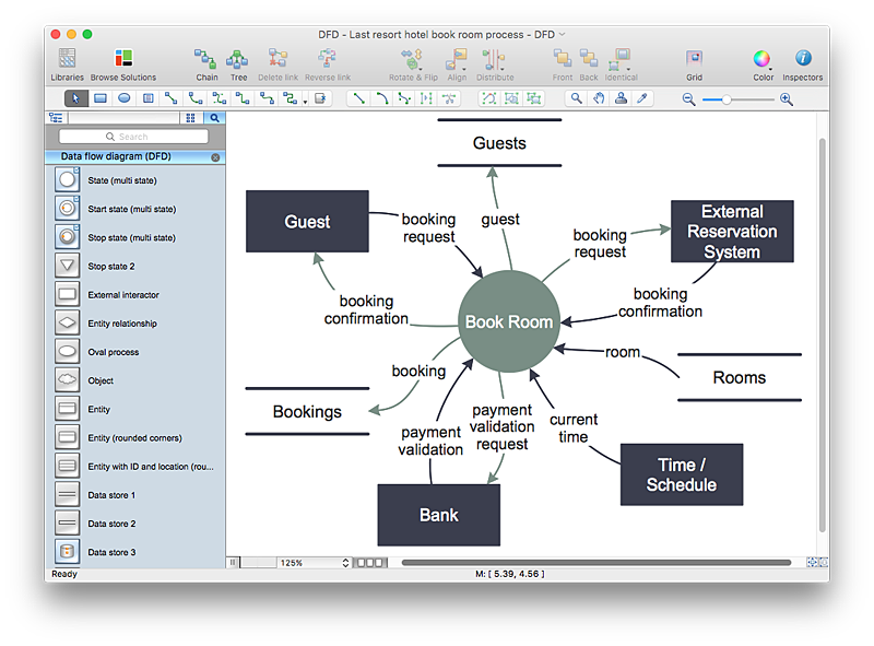
How to Create a Data Flow Diagram using ConceptDraw PRO
Data flow diagramming is a highly effective technique for showing the flow of information through a system. Data flow diagrams reveal relationships among and between the various components in a program or system. DFD is an important technique for modeling a system’s high-level detail by showing how input data is transformed to output results through a sequence of functional transformations. The set of standard symbols is used to depict how these components interact in a system. ConceptDraw PRO allows you to draw a simple and clear Data Flow Diagram using special libraries.
 Rapid UML
Rapid UML solution extends ConceptDraw PRO software with templates, samples and libraries of vector stencils for quick drawing the UML diagrams using Rapid Draw technology.
- Cloud Computing . Computer and Network Examples | Mobile cloud ...
- Diagramming tool - Amazon Web Services and Cloud Computing ...
- Diagramming tool - Amazon Web Services and Cloud Computing ...
- Computer network - Vector stencils library
- Diagramming tool - Amazon Web Services and Cloud Computing ...
- Diagramming tool - Amazon Web Services and Cloud Computing ...
- Diagramming tool - Amazon Web Services and Cloud Computing ...
- Diagramming tool - Amazon Web Services and Cloud Computing ...
- Diagramming tool - Amazon Web Services and Cloud Computing ...
- Internet symbols - Vector stencils library | Cloud Computing ...
- Sequence Diagram for Cloud Computing | Cloud Computing | ER ...
- Computer Network Diagrams | Cloud Computing . Computer and ...
- AWS Architecture Diagrams | Amazon Web Services Diagrams ...
- Mobile cloud architecture diagram | AWS Architecture Diagrams ...
- Amazon Web Services | AWS | How to Create an AWS Architecture ...
- How To create Diagrams for Amazon Web Services architecture ...
- Enterprise Architecture Diagrams | Amazon Web Services Diagrams ...
- Azure Storage | Workitems workflow diagram | Microsoft Azure ...
- Azure Storage | Azure Management | Azure Services | Azure ...
- Workitems workflow diagram | Competing consumers pattern | Valet ...
