The Data flow diagram (DFD) example "Payment for goods using UPS code scanner" shows data flow in process of payment for goods in the shop using the MaxiCode scanner.
"MaxiCode is a public domain, machine-readable symbol system originally created and used by United Parcel Service. Suitable for tracking and managing the shipment of packages, it resembles a barcode, but uses dots arranged in a hexagonal grid instead of bars. MaxiCode has been standardised under ISO/ IEC 16023.
A MaxiCode symbol (internally called "Bird's Eye", "Target", "dense code", or "UPS code") appears as a 1 inch square, with a bullseye in the middle, surrounded by a pattern of hexagonal dots. It can store about 93 characters of information, and up to 8 MaxiCode symbols can be chained together to convey more data. The centered symmetrical bullseye is useful in automatic symbol location regardless of orientation, and it allows MaxiCode symbols to be scanned even on a package traveling rapidly." [MaxiCode. Wikipedia]
This example of data flow diagram (Gane & Sarson notation) was created using the ConceptDraw PRO diagramming and vector drawing software extended with the Data Flow Diagrams solution from the Software Development area of ConceptDraw Solution Park.
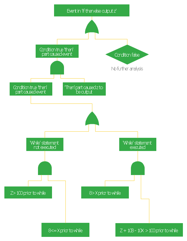
This FTA diagram example was redesigned from the Wikipedia Commons file: Example Code Fault Tree.jpg. [commons.wikimedia.org/ wiki/ File:Example_ Code_ Fault_ Tree.jpg]
"Use of Software Fault Tree Analysis.
Any SFTA must be preceded by a hazard analysis of the entire system. The information in the hazard analysis identifies those undesired events in the system that can cause serious consequences. It should be noted that in comple x systems not all hazards can be predetermined.
In this respect the technique does not claim to produce consistent results irrespective of the analyst. It is dependent on the judgment of the individual as to when to stop the process and which hazards to analyze.
The SFTA can be used at different stages of the software life cycle, beginning at the software requirements phase. At that early stage, only the bare minimum of the software will be defined, though the system will usually have a preliminary design. Only a very high-level SFTA will be able to be performed. However, as the software design progresses, and the code is developed, the SFTA can be “fleshed out” with the new information. High-level blocks can be broken down into specific components (modules, classes, methods, etc.)." [NASA Software Safety Guidebook. hq.nasa.gov/ office/ codeq/ doctree/ 871913.pdf]
The FTA diagram example "Code fault tree" was created using the ConceptDraw PRO diagramming and vector drawing software extended with the Fault Tree Analysis Diagrams solution from the Engineering area of ConceptDraw Solution Park.
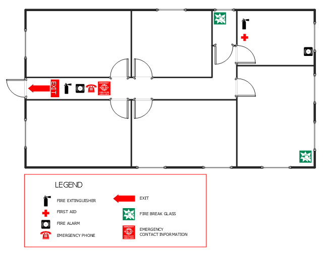
This office fire escape floor plan example shows layout of firefighting equipment and scheme of evacuation ways.
"Fire protection is the study and practice of mitigating the unwanted effects of potentially destructive fires. It involves the study of the behaviour, compartmentalisation, suppression and investigation of fire and its related emergencies, as well as the research and development, production, testing and application of mitigating systems. In structures, be they land-based, offshore or even ships, the owners and operators are responsible to maintain their facilities in accordance with a design-basis that is rooted in laws, including the local building code and fire code, which are enforced by the Authority Having Jurisdiction. Buildings must be constructed in accordance with the version of the building code that is in effect when an application for a building permit is made. Building inspectors check on compliance of a building under construction with the building code. Once construction is complete, a building must be maintained in accordance with the current fire code, which is enforced by the fire prevention officers of a local fire department. In the event of fire emergencies, Firefighters, fire investigators, and other fire prevention personnel called to mitigate, investigate and learn from the damage of a fire. Lessons learned from fires are applied to the authoring of both building codes and fire codes." [Fire protection. Wikipedia]
The example "Office fire and emergency plan" was created using the ConceptDraw PRO diagramming and vector drawing software extended with the Fire and Emergency Plans solution from the Building Plans area of ConceptDraw Solution Park.
www.conceptdraw.com/ solution-park/ building-fire-emergency-plans
The vector stencils library "HR symbols" contains 45 HR pictograms.
Use this icon set with HR symbols to draw your HR flowcharts, workflow diagrams, process charts and infographics with the ConceptDraw PRO diagramming and vector drawing software.
The HR pictograms library "HR symbols" is included in the HR Flowcharts solution from the Management area of ConceptDraw Solution Park.
Internet solutions with ConceptDraw PRO
ConceptDraw is a good means of visualization of information of any kind as it features powerful graphic capabilities. The conception of using ConceptDraw and open formats by the programs that work with Internet can be used for displaying any data and any structure in Internet.The vector stencils library "HR symbols" contains 45 HR pictograms.
Use this icon set with HR symbols to draw your HR flowcharts, workflow diagrams, process charts and infographics with the ConceptDraw PRO diagramming and vector drawing software.
The HR pictograms library "HR symbols" is included in the HR Flowcharts solution from the Management area of ConceptDraw Solution Park.
This vector stencils library contains 195 cloud computing icons.
Use it to design cloud computing infographic and diagrams with ConceptDraw PRO software.
"Cloud computing, also on-demand computing, is a kind of Internet-based computing that provides shared processing resources and data to computers and other devices on demand. It is a model for enabling ubiquitous, on-demand access to a shared pool of configurable computing resources (e.g., networks, servers, storage, applications and services), which can be rapidly provisioned and released with minimal management effort. Cloud computing and storage solutions provide users and enterprises with various capabilities to store and process their data in third-party data centers.
Cloud computing has become a highly demanded service or utility due to the advantages of high computing power, cheap cost of services, high performance, scalability, accessibility as well as availability." [Cloud computing. Wikipedia]
The vector stencils library "Cloud clipart" is included in the Cloud Computing Diagrams solution from the Computer and Networks area of ConceptDraw Solution Park.
The vector stencils library Alarm and access control contains 80 symbols of digital proximity equipment, locking hardware, and access control equipment.
"An alarm device or system of alarm devices gives an audible, visual or other form of alarm signal about a problem or condition. Alarm devices are often outfitted with a siren." [Alarm device. Wikipedia]
"An access control point, which can be a door, turnstile, parking gate, elevator, or other physical barrier, where granting access can be electronically controlled. Typically, the access point is a door. An electronic access control door can contain several elements. At its most basic, there is a stand-alone electric lock. The lock is unlocked by an operator with a switch. To automate this, operator intervention is replaced by a reader. The reader could be a keypad where a code is entered, it could be a card reader, or it could be a biometric reader. Readers do not usually make an access decision, but send a card number to an access control panel that verifies the number against an access list. To monitor the door position a magnetic door switch can be used. In concept, the door switch is not unlike those on refrigerators or car doors. Generally only entry is controlled, and exit is uncontrolled. In cases where exit is also controlled, a second reader is used on the opposite side of the door. In cases where exit is not controlled, free exit, a device called a request-to-exit (REX) is used. Request-to-exit devices can be a push-button or a motion detector. When the button is pushed, or the motion detector detects motion at the door, the door alarm is temporarily ignored while the door is opened. Exiting a door without having to electrically unlock the door is called mechanical free egress. This is an important safety feature. In cases where the lock must be electrically unlocked on exit, the request-to-exit device also unlocks the door." [Access control. Wikipedia]
Use the design elements library Alarm and access control for drawing layout floor plans, blueprints, and wiring diagrams of intrusion systems, time and attendance systems, card and code access control security systems, internal and external security control systems using the ConceptDraw PRO diagramming and vector drawing software.
The shapes library Alarm and access control is included in the Security and Access Plans solution from the Building Plans area of ConceptDraw Solution Park.
- Code 2 Flowchart
- Solving quadratic equation algorithm - Flowchart | Design A Pseudo ...
- Data flow diagram (DFD) - Payment for goods using UPS code ...
- Code fault tree | Preliminary Hazard Analysis
- Designing Pseudo Code Algorithm And Flow Chart To Solve ...
- Fire Code For Exit Doors
- Flowchart Symbols Code
- HR Flowchart Symbols | HR symbols - Vector stencils library | Smart ...
- Process Flowchart | Er Diagram For Bar Code Generator
- Process Flowchart | Seating Plans | Erd Of Bar Code Generator
- Dfd For Barcode System
- Flowchart To Pseudo Code In Mathematics
- Process Flowchart | Algorithm Flowchart And Code For Banking ...
- Dress code
- Emergency Plan Template | Office fire and emergency plan | Fire ...
- Construction Project Chart Examples | Program Evaluation and ...
- Uml Class Diagram
- Flow chart Example. Warehouse Flowchart | Data flow diagram ...
- Accounting Flowchart: Purchasing, Receiving, Payable and ...
- Invoice payment process - Flowchart | Data flow diagram (DFD ...
---payment-for-goods-using-ups-code-scanner.png--diagram-flowchart-example.png)





-cloud-clipart---vector-stencils-library.png--diagram-flowchart-example.png)
-cloud-clipart---vector-stencils-library.png--diagram-flowchart-example.png)

































































-cloud-clipart---vector-stencils-library.png--diagram-flowchart-example.png)








-cloud-clipart---vector-stencils-library.png--diagram-flowchart-example.png)
-cloud-clipart---vector-stencils-library.png--diagram-flowchart-example.png)
