The vector stencils library "Sales flowchart" contains 62 sales process flow chart symbols.
Use these flow chart icon set to draw your sales flowcharts, workflow diagrams and process charts with the ConceptDraw PRO diagramming and vector drawing software.
The sales process flowchart symbols library "Sales flowchart" is included in the Sales Flowcharts solution from the Marketing area of ConceptDraw Solution Park.
The vector stencils library "HR flowchart" contains 62 flowchart symbols.
Use it to draw your HR flowcharts, workflow diagrams and process charts with the ConceptDraw PRO diagramming and vector drawing software.
The flow chart symbols library "HR flowchart" is included in the HR Flowcharts solution from the Management area of ConceptDraw Solution Park.
Use it to draw your HR flowcharts, workflow diagrams and process charts with the ConceptDraw PRO diagramming and vector drawing software.
The flow chart symbols library "HR flowchart" is included in the HR Flowcharts solution from the Management area of ConceptDraw Solution Park.
This IVR diagram sample illustrates how ENUM works by giving an example: Subscriber A sets out to call Subscriber B:
1. The User Agent of an ENUM-enabled subscriber terminal device, or a PBX, or a Gateway, translates the request for the number +34 98 765 4321 in accordance with the rule described in RFC 3761 into the ENUM domain 1.2.3.4.5.6.7.8.9.4.3.e164.arpa.
2. A request is sent to the Domain Name System (DNS) asking it to look up the ENUM domain 1.2.3.4.5.6.7.8.9.4.3.e164.arpa.
3. The query returns a result in the form of so called Naming Authority Pointer Resource NAPTR records, as per RFC 3403. In the example above, the response is an address that can be reached in the Internet using the VoIP protocol, SIP per RFC 3261.
4. The terminal application now sets up a communication link, and the call is routed via the Internet.
This IVR diagram sample was designed on the base of the Wikimedia Commons file: Ejemplo ENUM.jpg. [commons.wikimedia.org/ wiki/ File:Ejemplo_ ENUM.jpg]
"Being able to dial telephone numbers the way customers have come to expect is considered crucial for the convergence of classic telephone service (PSTN) and Internet telephony (Voice over IP, VoIP), and for the development of new IP multimedia services. The problem of a single universal personal identifier for multiple communication services can be solved with different approaches. One simple approach is the Electronic Number Mapping System (ENUM), developed by the IETF, using existing E.164 telephone numbers, protocols and infrastructure to indirectly access different services available under a single personal identifier. ENUM also permits connecting the IP world to the telephone system in a seamless manner." [Telephone number mapping. Wikipedia]
The IVR diagram example "Example ENUM" was designed using ConceptDraw PRO diagramming and vector drawing software extended with the Interactive Voice Response Diagrams solution from the Computer and Networks area of ConceptDraw Solution Park.
"In computer networks, networked computing devices pass data to each other along data connections. The connections (network links) between nodes are established using either cable media or wireless media. ...
Network computer devices that originate, route and terminate the data are called network nodes. Nodes can include hosts such as personal computers, phones, servers as well as networking hardware. ...
Network links.
The communication media used to link devices to form a computer network include electrical cable (HomePNA, power line communication, G.hn), optical fiber (fiber-optic communication), and radio waves (wireless networking). In the OSI model, these are defined at layers 1 and 2 - the physical layer and the data link layer.
A widely adopted family of communication media used in local area network (LAN) technology is collectively known as Ethernet. The media and protocol standards that enable communication between networked devices over Ethernet are defined by IEEE 802.3. Ethernet transmit data over both copper and fiber cables. Wireless LAN standards (e.g. those defined by IEEE 802.11) use radio waves, or others use infrared signals as a transmission medium. Power line communication uses a building's power cabling to transmit data. ...
Network nodes.
Apart from the physical communications media described above, networks comprise additional basic system building blocks, such as network interface controller (NICs), repeaters, hubs, bridges, switches, routers, modems, and firewalls." [Computer network. Wikipedia]
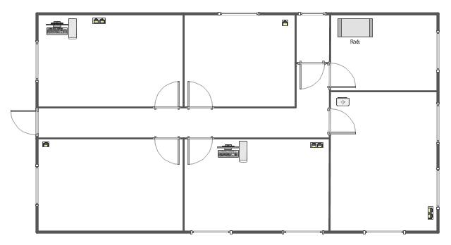
The network equipment and cabling layout floorplan template for the ConceptDraw PRO diagramming and vector drawing software is included in the Network Layout Floor Plans solution from the Computer and Networks area of ConceptDraw Solution Park.
The vector stencils library "Sales flowchart" contains 62 sales process flow chart symbols.
Use these flow chart icon set to draw your sales flowcharts, workflow diagrams and process charts with the ConceptDraw PRO diagramming and vector drawing software.
The sales process flowchart symbols library "Sales flowchart" is included in the Sales Flowcharts solution from the Marketing area of ConceptDraw Solution Park.
Use these flow chart icon set to draw your sales flowcharts, workflow diagrams and process charts with the ConceptDraw PRO diagramming and vector drawing software.
The sales process flowchart symbols library "Sales flowchart" is included in the Sales Flowcharts solution from the Marketing area of ConceptDraw Solution Park.
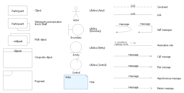
The vector stencils library "UML communication diagrams" contains 23 symbols for the ConceptDraw PRO diagramming and vector drawing software.
"... communication diagrams use the free-form arrangement of objects and links as used in Object diagrams. In order to maintain the ordering of messages in such a free-form diagram, messages are labeled with a chronological number and placed near the link the message is sent over. Reading a communication diagram involves starting at message 1.0, and following the messages from object to object." [Communication diagram. Wikipedia]
The example "Design elements - UML communication diagrams" is included in the Rapid UML solution from the Software Development area of ConceptDraw Solution Park.
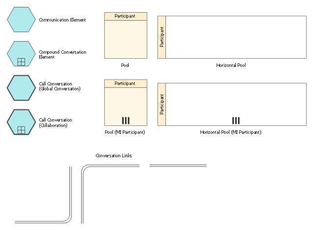
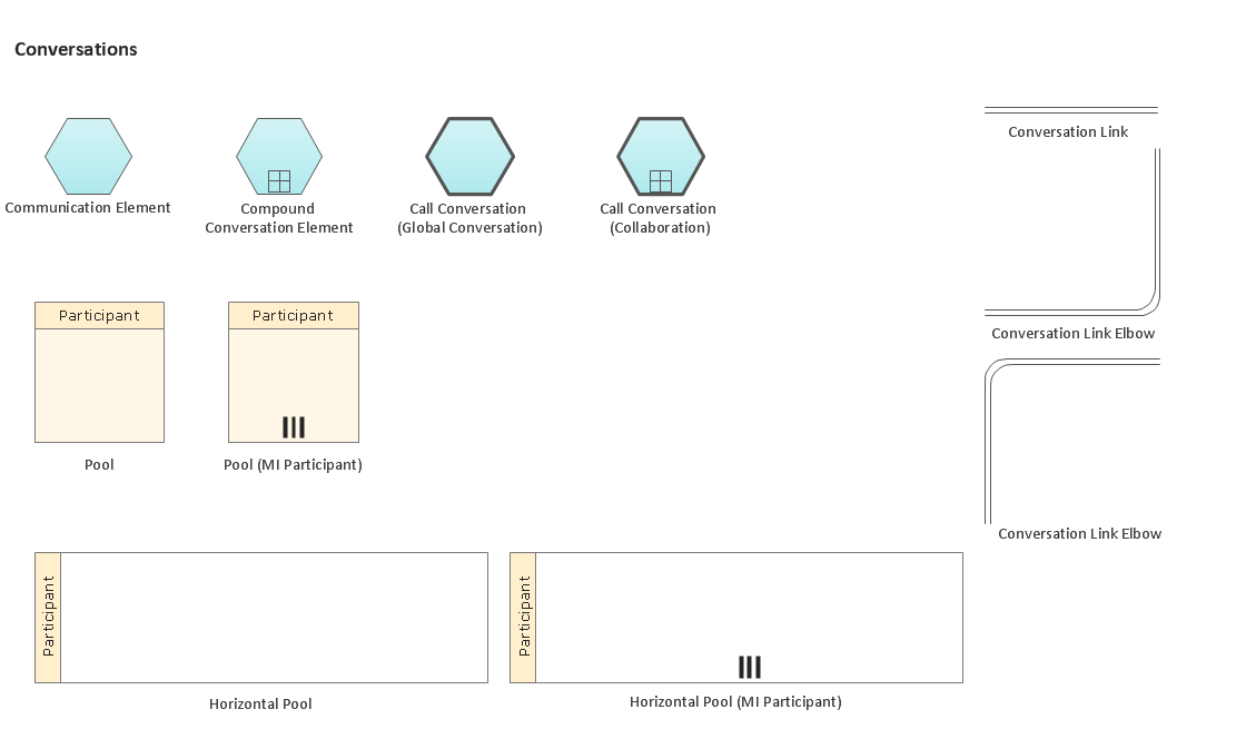
The vector stencils library "Conversations" contains 11 symbols: communication element, compound conversation element, call conversation (global and collaboration), conversation links, pools. Use these shapes for drawing BPMN 2.0 conversation diagrams using the ConceptDraw PRO diagramming and vector drawing software.
"Conversation-Model.
The new Conversation-Model is used to model a "who with whom and what"-view of processes. All process participants can be included in a compact form of modeling as long as denoting which communication is involved.
Process participants are represented as Pools (collapsed...) in Conversation-Models. The Communication-Shape defines a set of logically related message exchanges which are tied to Pools via Conversation-Links. If there is a multi-instanced Pool (also introduced with BPMN 2.0) involved, a Forked Conversation-Link is used for it.
Furthermore Sub-Conversations can be used to define abstractions." [en.bpmn-community.org/ tutorials/ 34/ ]
The example "Design elements - Conversations (BPMN 2.0)" is included in the Business Process Diagram solution from the Business Processes area of ConceptDraw Solution Park.
Business Process Elements: Conversations
Create professional business process diagrams using ConceptDraw Conversations library with 11 objects from BPMN.
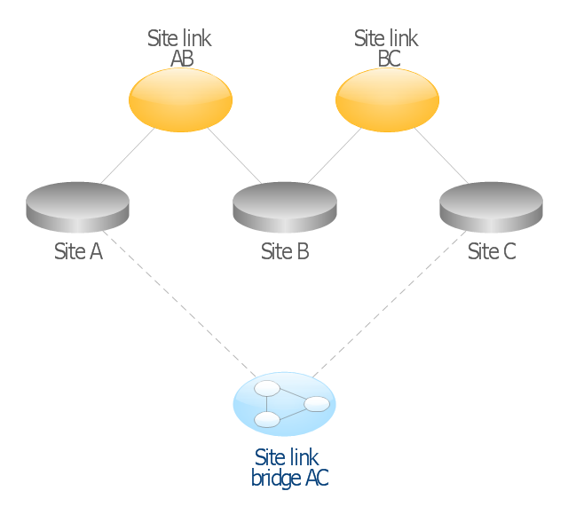
This AD diagram example was redesigned from the picture "Site links" from the book "Active Directory for Dummies".
"Site links represent the Active Directory replication paths between sites.
These paths are manually defined so that the designer has control over which network links the replication traffic occurs on. These site links also control how clients are directed to domain controllers when there’s no DC in the client’s local site. Each site link has the following attributes:
(1) Connected sites: A site link is defined by the sites to which it connects. A site link can connect two or more sites together.
(2) Network transport: Site links support replication communication over IP-based RPCs or with the Simple Mail Transport Protocol (SMTP). You normally want to use RPC whenever possible, but you can use SMTP when the sites you’re linking don’t support RPC.
(3) Cost: Each site link has a cost associated with it. Costs are used to assign preferences to links that determine which link should be followed when multiple link paths are available between sites. The cost represents what it “costs” to use this site link relative to the other site links and affects replication traffic as well as how users are assigned a domain controller. Links with lower cost values have preference over links with higher cost values. Cost values range from 1–32,767; the default being 100.
(4) Frequency: The frequency value defines how often a replication occurs
when using this site link (the replication latency). You can configure the time between replications from a minimum of 15 minutes to a maximum of 10,080 minutes (one week). The default frequency is 180 minutes.
(5) Schedule: The schedule dictates when this link is active and available for replication between the sites. The schedule can also control which days of the week the link is available. Normally, the schedule is set so that the link is available 24 hours a day, but you can set up different schedules on a per-day-of-the-week basis.
By creating a site link, you enable two or more sites to be connected and to share the same site link attributes (transport, cost, frequency, and schedule). By default, site links create transitive connectivity between sites.
If you create a site link between sites A and B and another site link between
sites B and C, an automatic connection (known as a site link bridge) is created between sites A and C..." [Steve Clines and Marcia Loughry, Active Directory® For Dummies®, 2nd Edition. 2008]
The Active Directory diagram example "Site links" was created using the ConceptDraw PRO diagramming and vector drawing software extended with the Active Directory Diagrams solution from the Computer and Networks area of ConceptDraw Solution Park.
- Communication Links Examples
- Symbol Of Communication Link In Flow Chart
- Microwave Communication Link Design Devices
- Communication link
- Wireless Communication Link Symbol
- Diagram Of Link In Data Communication
- Telecommunication Network Diagrams | Telecommunication ...
- Sales flowchart - Vector stencils library | Fault tree analysis diagrams ...
- Gestures Communication
- Communication Symbols
- Start Link
- Swim Lane Flowchart Symbols | Sales flowchart - Vector stencils ...
- Basic Flowchart Symbols and Meaning | Sales flowchart - Vector ...
- Diagram Of Physical Communication Guided Or Unguided Media
- Diagram Of Telephone Communication System
- Performance Indicators | Design elements - Sales dashboard | Sales ...
- Gesture Communication Example
- Basic Flowchart Symbols and Meaning | Process Flowchart | Internal ...
- Example ENUM | Business Diagram Software | Network ...
- Design elements - IDEF3 process schematic symbols | Vector ...

-sales-flowchart---vector-stencils-library.png--diagram-flowchart-example.png)
-sales-flowchart---vector-stencils-library.png--diagram-flowchart-example.png)

-sales-flowchart---vector-stencils-library.png--diagram-flowchart-example.png)

-sales-flowchart---vector-stencils-library.png--diagram-flowchart-example.png)
-sales-flowchart---vector-stencils-library.png--diagram-flowchart-example.png)

-sales-flowchart---vector-stencils-library.png--diagram-flowchart-example.png)








-sales-flowchart---vector-stencils-library.png--diagram-flowchart-example.png)

-sales-flowchart---vector-stencils-library.png--diagram-flowchart-example.png)






-sales-flowchart---vector-stencils-library.png--diagram-flowchart-example.png)
-sales-flowchart---vector-stencils-library.png--diagram-flowchart-example.png)




-hr-flowchart---vector-stencils-library.png--diagram-flowchart-example.png)
-hr-flowchart---vector-stencils-library.png--diagram-flowchart-example.png)

-hr-flowchart---vector-stencils-library.png--diagram-flowchart-example.png)

-hr-flowchart---vector-stencils-library.png--diagram-flowchart-example.png)
-hr-flowchart---vector-stencils-library.png--diagram-flowchart-example.png)

-hr-flowchart---vector-stencils-library.png--diagram-flowchart-example.png)




-hr-flowchart---vector-stencils-library.png--diagram-flowchart-example.png)

-hr-flowchart---vector-stencils-library.png--diagram-flowchart-example.png)


-hr-flowchart---vector-stencils-library.png--diagram-flowchart-example.png)
-hr-flowchart---vector-stencils-library.png--diagram-flowchart-example.png)


