This PFD sample was redesigned from the Wikipedia file: NaturalGasCondensate.png.
"This is a schematic flow diagram of a typical facility for separating and recovering liquid condensate from raw natural gas."
[en.wikipedia.org/ wiki/ File:NaturalGasCondensate.png]
"Natural-gas condensate is a low-density mixture of hydrocarbon liquids that are present as gaseous components in the raw natural gas produced from many natural gas fields. It condenses out of the raw gas if the temperature is reduced to below the hydrocarbon dew point temperature of the raw gas.
The natural gas condensate is also referred to as simply condensate, or gas condensate, or sometimes natural gasoline because it contains hydrocarbons within the gasoline boiling range. Raw natural gas may come from any one of three types of gas wells:
(1) Crude oil wells - Raw natural gas that comes from crude oil wells is called associated gas. This gas can exist separate from the crude oil in the underground formation, or dissolved in the crude oil.
(2) Dry gas wells - These wells typically produce only raw natural gas that does not contain any hydrocarbon liquids. Such gas is called non-associated gas.
(3) Condensate wells - These wells produce raw natural gas along with natural gas liquid. Such gas is also non-associated gas and often referred to as wet gas." [Natural-gas condensate. Wikipedia]
The process flow diagram example "Natural gas condensate - PFD" was drawn using the ConceptDraw PRO software extended with the Chemical and Process Engineering solution from the Chemical and Process Engineering area of ConceptDraw Solution Park.
Process Diagrams
ConceptDraw PRO diagramming and vector drawing software extended with Chemical and Process Engineering Solution from the Engineering Area of ConceptDraw Solution Park offers you the set of useful tools for easy drawing various Process Diagrams.
 Chemical and Process Engineering
This chemical engineering solution extends ConceptDraw PRO v.9.5 (or later) with process flow diagram symbols, samples, process diagrams templates and libraries of design elements for creating process and instrumentation diagrams, block flow diagrams (BFD
- Amine treating unit schematic diagram | Natural gas condensate ...
- Process flow diagram ( PFD ) template | Crude oil distillation unit ...
- Natural gas condensate - PFD
- Natural gas condensate - PFD | Bar Diagram Math | Affinity Diagram ...
- Natural gas condensate - PFD | Resources and energy - Vector ...
- Natural gas condensate - PFD | Crude oil distillation unit - PFD ...
- Natural gas condensate - PFD | Watercraft - Vector stencils library ...
- Chemical and Process Engineering | Natural gas condensate - PFD ...
- Natural gas condensate - PFD | EU greenhouse gas emissions ...
- Gravity filtration of liquids | Hydraulic schematic | Natural gas ...
- Natural gas condensate - PFD | Divided bar graph - Global natural ...
- Amine treating unit schematic diagram | Process flow diagram ( PFD ...
- Crude oil distillation unit - PFD | Process flow diagram - Typical oil ...
- Crude oil distillation unit - PFD | Petroleum products yielded from ...
- Pfd Samples
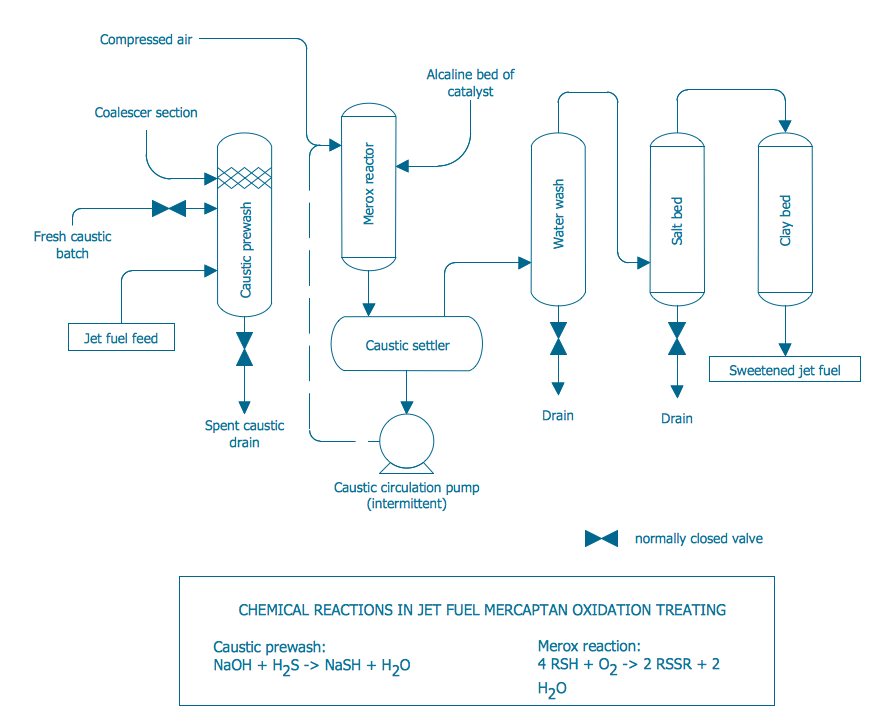
- Jet fuel mercaptan oxidation treating - PFD | Amine treating unit ...
- Process flow diagram - Typical oil refinery | Crude oil distillation unit ...
- Process flow diagram - Typical oil refinery | Process Flowchart ...
- Process Flowchart | Chemical and Process Engineering | Process ...
- Chemical and Process Engineering | Process flow diagram ( PFD ...
-natural-gas-condensate---pfd.png--diagram-flowchart-example.png)
