Electrical Symbols — Integrated Circuit

Electrical Drawing Software and Electrical Symbols

Electrical Symbols — Resistors

Electrical Symbols — Composite Assemblies

Electrical Symbols — Lamps, Acoustics, Readouts

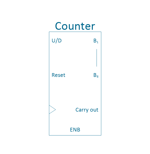
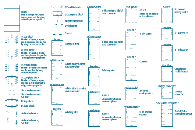
The vector stencils library "Integrated circuit" contains 43 components of integrated circuits.
Use these shapes for integrated circuit design, including transducers, rotary devices, converters, registers, analog switches, counters, registers, decoders, and multiplex transmitters in the ConceptDraw PRO diagramming and vector drawing software extended with the Electrical Engineering solution from the Engineering area of ConceptDraw Solution Park.
www.conceptdraw.com/ solution-park/ engineering-electrical
4X top block
4X base block
Board
4X middle block
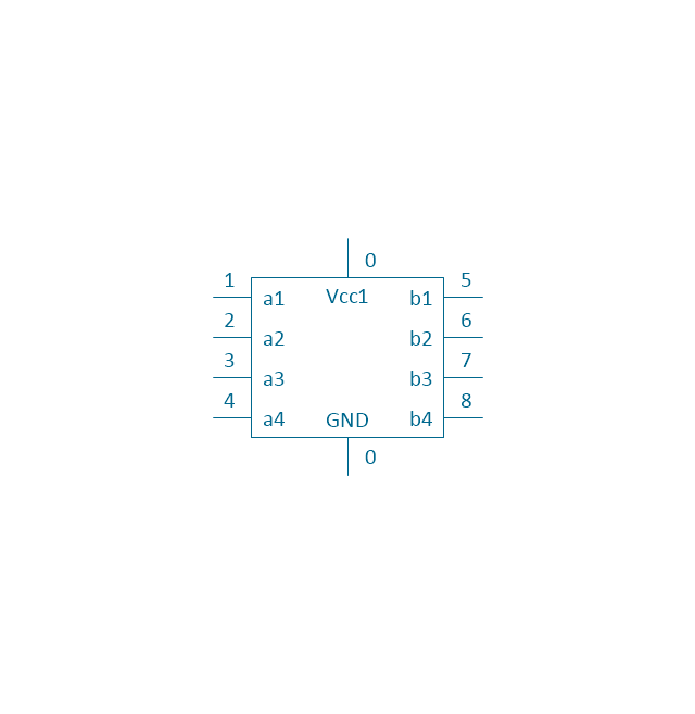
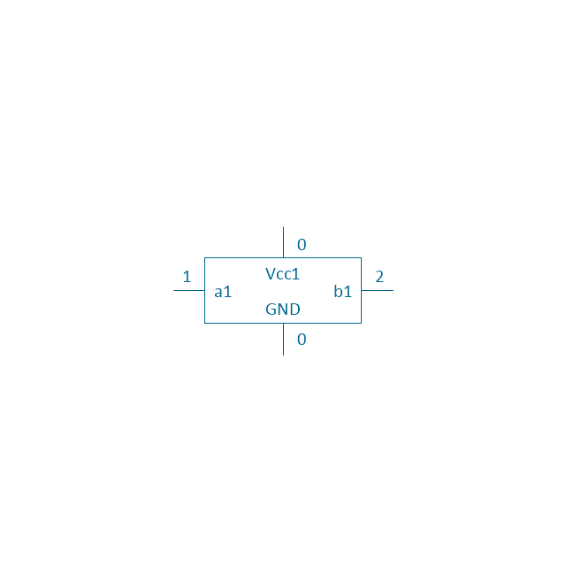
4X complete block
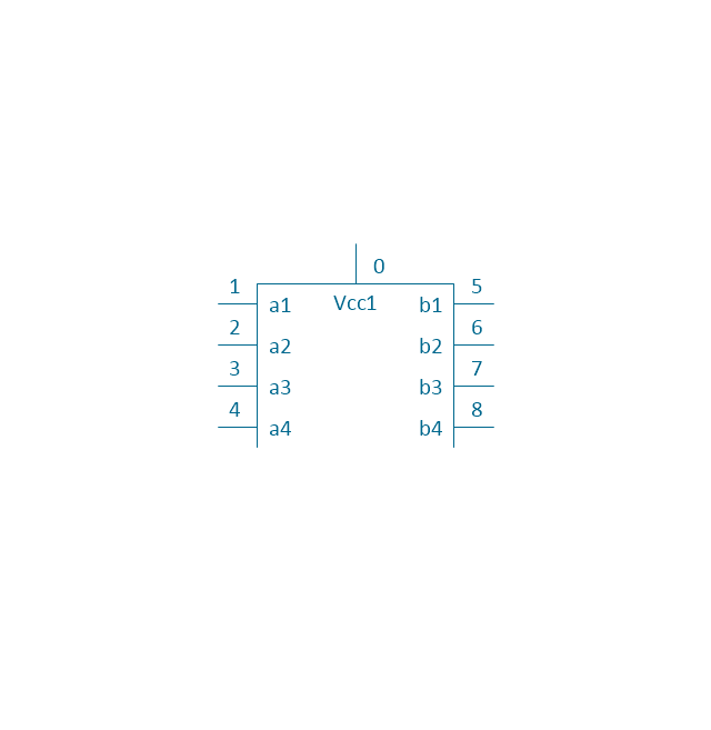
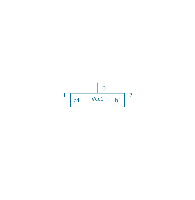
1X top block
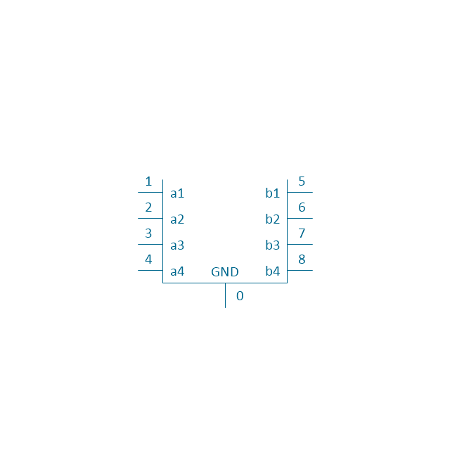
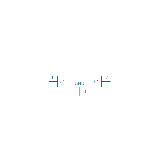
1X base block
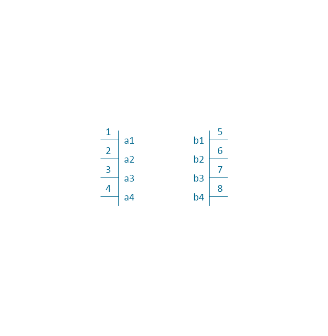
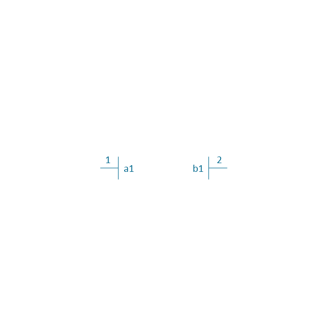
1X middle block
1X complete block
Negative logic dot

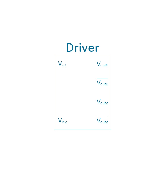
Driver
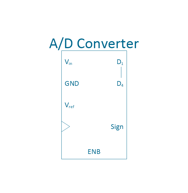
4-bit a/d converter
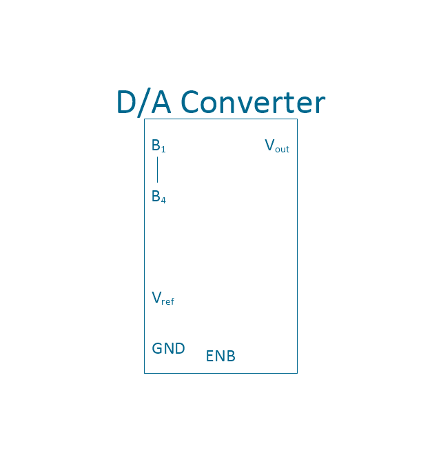
4-bit d/a converter
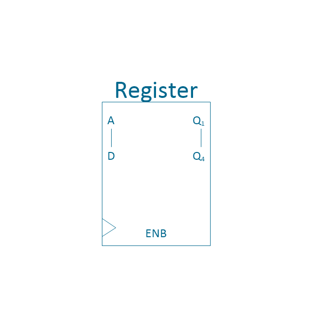
4-bit register
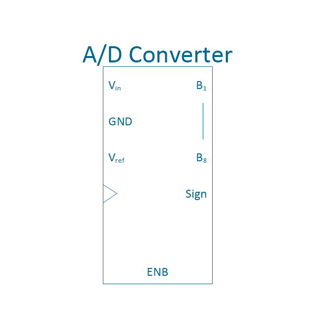
8-bit a/d converter
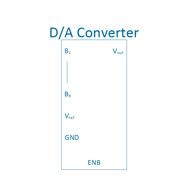
8-bit d/a converter
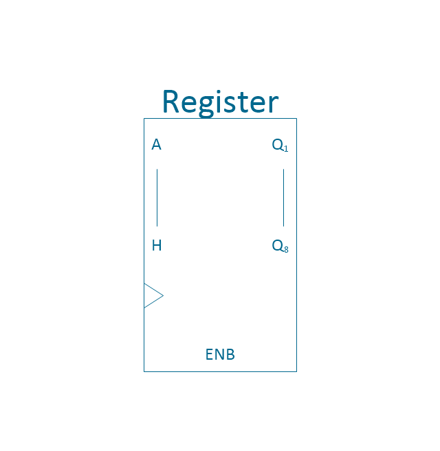
8-bit register
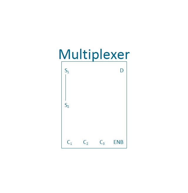
MUX 2
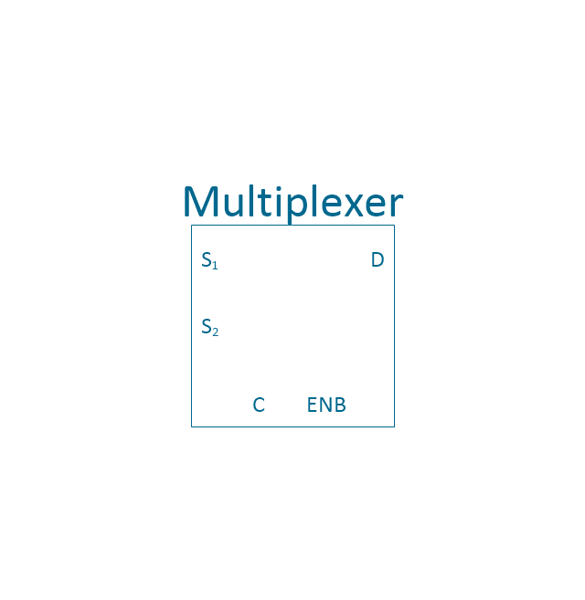
MUX 4
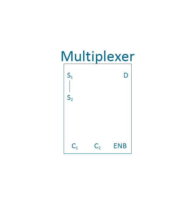
MUX 8
4-bit counter
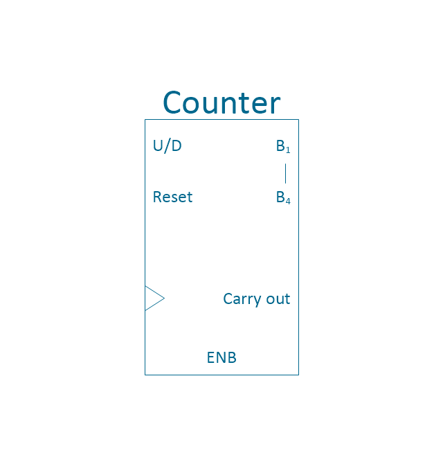
Counter
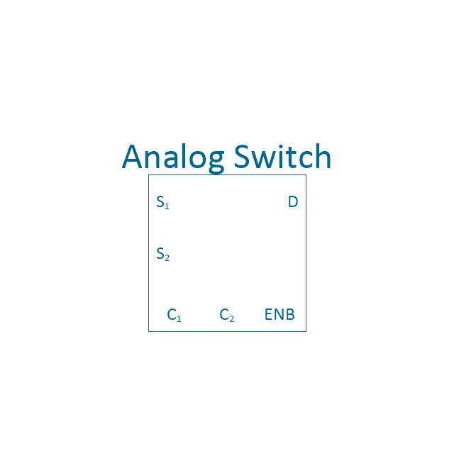
Analog switch 2
Preload counter 4
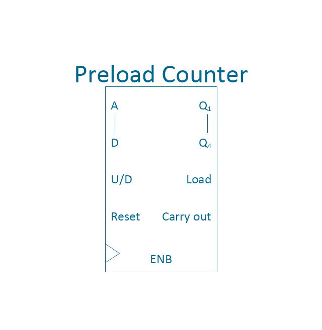
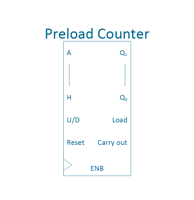
Preload Counter
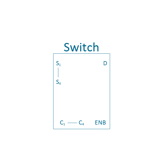
Analog switch 4
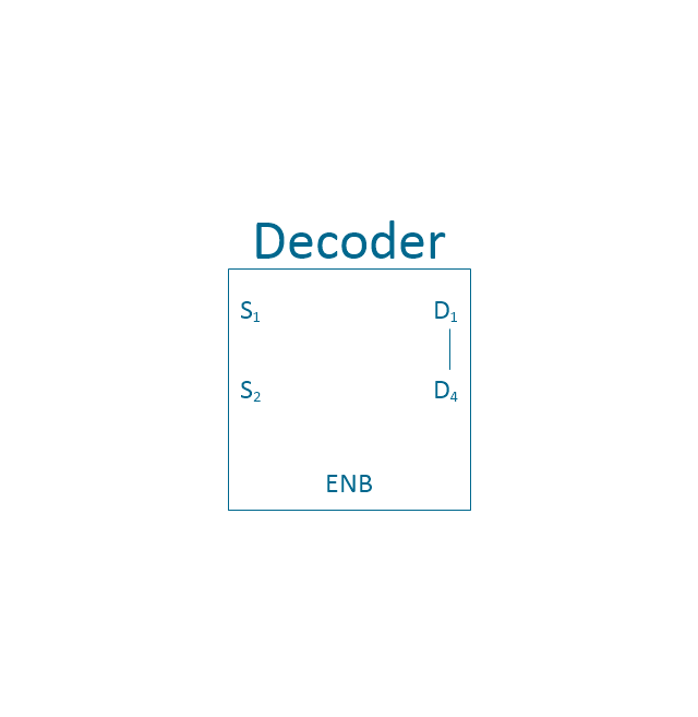
2 - 4 decoder
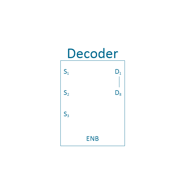
3 - 8 decoder
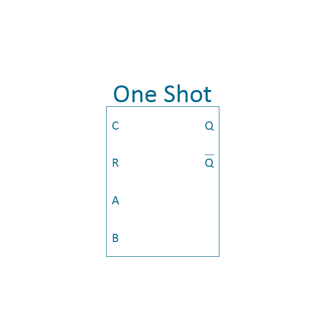
One shot
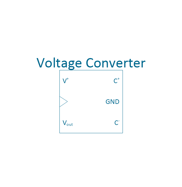
Voltage converter
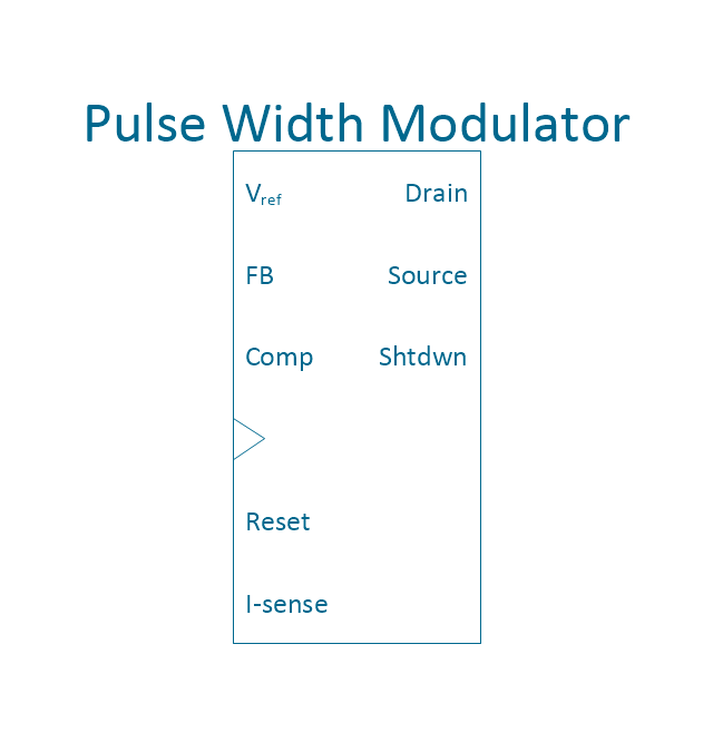
PWM
Horizontal extension
Horizontal extension 2

Horizontal extension, overline
Horizontal extension, overline 2
Vertical extension

Vertical extension 2

Vertical extension, overline

Vertical extension, overline 2

Switch point

Switch point 2

Ground

Ground 2

Electrical Symbols — Delay Elements

The vector stencils library "Integrated circuit" contains 43 component symbols: transducers, rotary devices, converters, registers, analog switches, counters, registers, decoders, and multiplex transmitters.
"An integrated circuit or monolithic integrated circuit (also referred to as an IC, a chip, or a microchip) is a set of electronic circuits on one small plate ("chip") of semiconductor material, normally silicon. This can be made much smaller than a discrete circuit made from independent components.
Integrated circuits are used in virtually all electronic equipment today and have revolutionized the world of electronics. Computers, mobile phones, and other digital home appliances are now inextricable parts of the structure of modern societies, made possible by the low cost of producing integrated circuits." [Integrated circuit. Wikipedia]
The symbols example "Design elements - Integrated circuit" was drawn using the ConceptDraw PRO diagramming and vector drawing software extended with the Electrical Engineering solution from the Engineering area of ConceptDraw Solution Park.
Integrated circuit components
Electrical Symbols, Electrical Diagram Symbols

Electrical Symbols — Transistors
Circuits and Logic Diagram Software

Electrical Symbols — Logic Gate Diagram

Electrical Symbols — Rotating Equipment

The vector stencils library "Integrated circuit" contains 43 components of integrated circuits.
Use these shapes for integrated circuit design, including transducers, rotary devices, converters, registers, analog switches, counters, registers, decoders, and multiplex transmitters in the ConceptDraw PRO diagramming and vector drawing software extended with the Electrical Engineering solution from the Engineering area of ConceptDraw Solution Park.
www.conceptdraw.com/ solution-park/ engineering-electrical
Use these shapes for integrated circuit design, including transducers, rotary devices, converters, registers, analog switches, counters, registers, decoders, and multiplex transmitters in the ConceptDraw PRO diagramming and vector drawing software extended with the Electrical Engineering solution from the Engineering area of ConceptDraw Solution Park.
www.conceptdraw.com/ solution-park/ engineering-electrical
4X top block
4X base block
Board
4X middle block
4X complete block
1X top block
1X base block
1X middle block
1X complete block
Negative logic dot
Driver
4-bit a/d converter
4-bit d/a converter
4-bit register
8-bit a/d converter
8-bit d/a converter
8-bit register
MUX 2
MUX 4
MUX 8
4-bit counter
Counter
Analog switch 2
Preload counter 4
Preload Counter
Analog switch 4
2 - 4 decoder
3 - 8 decoder
One shot
Voltage converter
PWM
Horizontal extension
Horizontal extension 2
Horizontal extension, overline
Horizontal extension, overline 2
Vertical extension
Vertical extension 2
Vertical extension, overline
Vertical extension, overline 2
Switch point
Switch point 2
Ground
Ground 2
ConceptDraw Arrows10 Technology
- Electrical Symbols — Electrical Circuits | Design elements ...
- Circuit Symbols
- Design elements - Integrated circuit | Electrical Drawing Software ...
- Electrical Symbols — Integrated Circuit | Electrical Symbols ...
- Integrated Logic Circuits
- Automotive Wiring Symbols
- Electrical Symbols, Electrical Diagram Symbols | Electrical Symbols ...
- Integrated circuit - Vector stencils library | Integrated circuit - Vector ...
- Electrical Symbols — Electrical Circuits | Electrical Symbols ...
- Electrical Symbols — Composite Assemblies | Electrical Symbols ...
- Circuit Components And Symbols
- How To use House Electrical Plan Software | Electrical Symbols ...
- Electrical Symbols, Electrical Diagram Symbols | Electrical Symbols ...
- Wiring Diagrams with ConceptDraw PRO
- Symbol Of The Elements Of Electronic Component Used In Circuit
- Pdf Transistors Circuits Symbols And Their Uses
- Element Of Circuit Board
- Electronic Circuit Diagram Assemblies Free Video Download
- Electrical Drawing Software and Electrical Symbols | Circuits and ...
- Electrical Symbols, Electrical Diagram Symbols | Electrical Drawing ...