HelpDesk
How to Draw a Chemical Process Flow Diagram
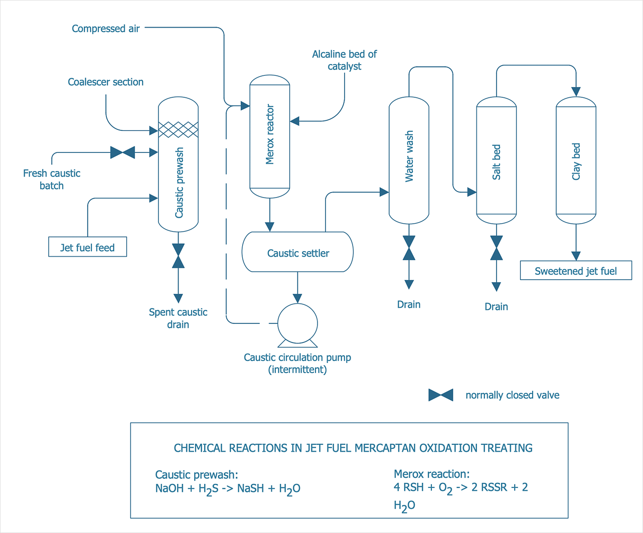
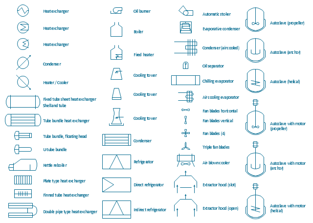
Process Flow Diagram widely used in modeling of processes in the chemical industry. A Chemical Process Flow diagram (PFD) is a specialized type of flowchart. With the help of Chemical Process Flow Diagram engineers can easily specify the general scheme of the processes and chemical plant equipment. Chemical Process Flow Diagram displays the real scheme of the chemical process, the relationship between the equipment and the technical characteristics of the process. Chemical Process Flow Diagram illustrates the connections between the basic equipment as well as the overall structure of pipelines and other supporting equipment. The purpose of the PFD is to build the image of the basic idea of the chemical process. ConceptDraw DIAGRAM together with its Chemical and Process Engineering solution delivers the possibility to design Chemical Process Flow diagrams. It is designed for chemical industry engineers and designers.The vector stencils library "Heating equipment" contains 42 symbols of regenerators, intercoolers, heaters, and condensers.
Use these shapes for drawing cooling systems, heat recovery systems, thermal, heat transfer and mechanical design, and process flow diagrams (PFD).
"Heating or cooling of processes, equipment, or enclosed environments are within the purview of thermal engineering.
One or more of the following disciplines may be involved in solving a particular thermal engineering problem:
Thermodynamics,
Fluid mechanics,
Heat transfer,
Mass transfer.
Thermal engineering may be practiced by mechanical engineers and chemical engineers.
One branch of knowledge used frequently in thermal engineering is that of thermofluids." [Thermal engineering. Wikipedia]
The design elements example "Heating equipment" was created using the ConceptDraw PRO diagramming and vector drawing software extended with the Chemical and Process Engineering solution from the Engineering area of ConceptDraw Solution Park.
 Chemical and Process Engineering
This chemical engineering solution extends ConceptDraw DIAGRAM.9.5 (or later) with process flow diagram symbols, samples, process diagrams templates and libraries of design elements for creating process and instrumentation diagrams, block flow diagrams (BFD
The vector stencils library "Heating equipment" contains 42 symbols of regenerators, intercoolers, heaters, and condensers.
Use these shapes for drawing cooling systems, heat recovery systems, thermal, heat transfer and mechanical design, and process flow diagrams (PFD) in the ConceptDraw PRO software extended with the Chemical and Process Engineering solution from the Chemical and Process Engineering area of ConceptDraw Solution Park.
www.conceptdraw.com/ solution-park/ engineering-chemical-process
Bubble diagrams in Landscape Design with ConceptDraw DIAGRAM
Bubble Diagrams are the charts with a bubble presentation of data with obligatory consideration of bubble's sizes. They are analogs of Mind Maps and find their application at many fields, and even in landscape design. At this case the bubbles are applied to illustrate the arrangement of different areas of future landscape design, such as lawns, flowerbeds, playgrounds, pools, recreation areas, etc. Bubble Diagram helps to see instantly the whole project, it is easy for design and quite informative, in most cases it reflects all needed information. Often Bubble Diagram is used as a draft for the future landscape project, on the first stage of its design, and in case of approval of chosen design concept is created advanced detailed landscape plan with specification of plants and used materials. Creation of Bubble Diagrams for landscape in ConceptDraw DIAGRAM software is an easy task thanks to the Bubble Diagrams solution from "Diagrams" area. You can use the ready scanned location plan as the base or create it easy using the special ConceptDraw libraries and templates.The vector stencils library "Chemical engineering" contains 24 symbols of chemical and process engineering equipment.
Use these shapes for drawing Process Flow Diagrams (PFD), Piping and Instrumentation Diagrams (P&ID), and Water Flow Diagrams in the ConceptDraw PRO software extended with the Chemical and Process Engineering solution from the Chemical and Process Engineering area of ConceptDraw Solution Park.
www.conceptdraw.com/ solution-park/ engineering-chemical-process
- Pfd Heater Symbol
- Process Flow Diagram Symbols | Design elements - Heating ...
- Evaporator Pfd Symbol
- Process Flow Diagram Symbols | Chemical and Process ...
- Reboiler Symbol
- Chemical engineering - Vector stencils library | Blower Fan Pfd
- Mechanical Drawing Symbols | Process Flow Diagram Symbols ...
- Heat Exchanger Shell And Tube Pfd Symbol
- Symbol For Direct Fired Heater
- Process Flow Diagram Symbols | How To use House Electrical Plan ...
- Process Flow Diagram Symbols | Chemical Engineering ...
- Evaporator Process Symbol
- Pfd Logo For A Flash Separator
- Process Symbol Evaporator
- Symbol Of Condenser In Flow Sheet
- Process Flowchart | Process Flow Diagram Symbols | Design ...
- Process Flow Diagram Symbols | Design elements - HVAC control ...
- Crude oil distillation unit - PFD | Air Cooler Line Diagram
- Process flow diagram ( PFD ) template | Heating equipment - Vector ...


















-heating-equipment---vector-stencils-library.png--diagram-flowchart-example.png)



-heating-equipment---vector-stencils-library.png--diagram-flowchart-example.png)
-heating-equipment---vector-stencils-library.png--diagram-flowchart-example.png)
-heating-equipment---vector-stencils-library.png--diagram-flowchart-example.png)
-heating-equipment---vector-stencils-library.png--diagram-flowchart-example.png)
-heating-equipment---vector-stencils-library.png--diagram-flowchart-example.png)
-heating-equipment---vector-stencils-library.png--diagram-flowchart-example.png)
-heating-equipment---vector-stencils-library.png--diagram-flowchart-example.png)
-heating-equipment---vector-stencils-library.png--diagram-flowchart-example.png)


-heating-equipment---vector-stencils-library.png--diagram-flowchart-example.png)


