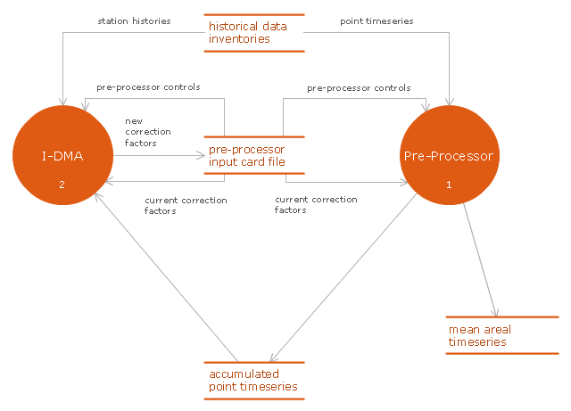
This DFD sample was created on the base of figure illustrating the "Interactive Double Mass Analysis. User's Guide" from the website of the Office of Hydrologic Development of the National Weather Service (NWS) of the National Oceanic and Atmospheric Administration (NOAA).
"Double mass analysis is a technique commonly employed to determine corrections to hydrometeorological data to account for changes in data collection procedures or other local conditions. The changes may result from a variety of things including changes in instrumentation, changes in observation procedures, or changes in gage location or surrounding conditions. The purpose of this Interactive Double Mass Analysis (IDMA) tool is to provide an effective and efficient way for users to perform consistency checking using double mass analysis and to produce the correction factors that are used in subsequent processing by NWSRFS preprocessor tools to account for any discovered inconsistencies.
Computations of mean areal time series for use in calibration and ESP have traditionally been made using the appropriate preprocessing software (MAP, PXPP, MAT etc.). The preprocessors have traditionally taken point time series as input and have provided facilities for estimation of missing data, and for consistency checking and correction in addition to the mean areal computations. The IDMA tool has been designed to run in conjunction with the preprocessors in an iterative fashion. It performs the consistency checking function, leaving the estimation, correction and mean areal computations to the preprocessors. ...
As shown in Figure ... the preprocessor software generates a data file that contains accumulated data values for each station and the associated group base, as well as flags indicating whether the values were estimated or not. This data file along with the input card file used by the preprocessor are used by the IDMA tool. The IDMA tool then allows the user to perform consistency checks and to calculate correction factors. The correction factors are then returned so that the preprocessors can perform the corrections, re-estimate missing data and perform the mean areal computations. Note that there is an interdependence between the estimation of missing values in the preprocessors and the correction factors computed in the IDMA and so there needs to be iteration between the two processes until the user is satisfied that an appropriate balance has been reached."
[nws.noaa.gov/ oh/ hrl/ idma/ users_ guide/ html/ dma_ overview.php]
The example "Interaction between IDMA and preprocessor" was created using the ConceptDraw PRO diagramming and vector drawing software extended with the Data Flow Diagrams solution from the Software Development area of ConceptDraw Solution Park.
Account Flowchart Stockbridge System. Flowchart Examples
Create your own flow charts of data processing systems using the ConceptDraw DIAGRAM diagramming and vector drawing software extended with the Cross-Functional Flowcharts solution from the Business Processes area of ConceptDraw Solution Park. This is a flowchart of a data processing system combining manual and computerized processing to handle accounts receivable, billing, and general ledger.
 ConceptDraw Solution Park
ConceptDraw Solution Park collects graphic extensions, examples and learning materials
HelpDesk
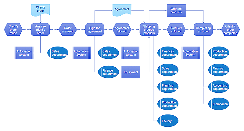
Event-driven Process Chain (EPC) Diagram Software
An EPC diagram is a type of flowchart used in business process analysis. It shows different business processes through various work flows. The workflows are shown as processes and events that are related to different executes and tasks that allow business workflow to be completed. An EPC diagram shows different business processes through various workflows. The workflows are seen as functions and events that are connected by different teams or people, as well as tasks that allow business processes to be executed. The best thing about this type of enterprise modelling is that creating an EPC diagram is quick and simple as long as you have the proper tool. One of the main usages of the EPC diagrams is in the modelling, analyzing and re-engineering of business processes. With the use of the flowchart, businesses are able to see inefficiencies in the processes and modify to make them more productive. Event-driven process chain diagrams are also used to configure an enterprise resource pla
 ConceptDraw Solution Park
ConceptDraw Solution Park collects graphic extensions, examples and learning materials
HelpDesk
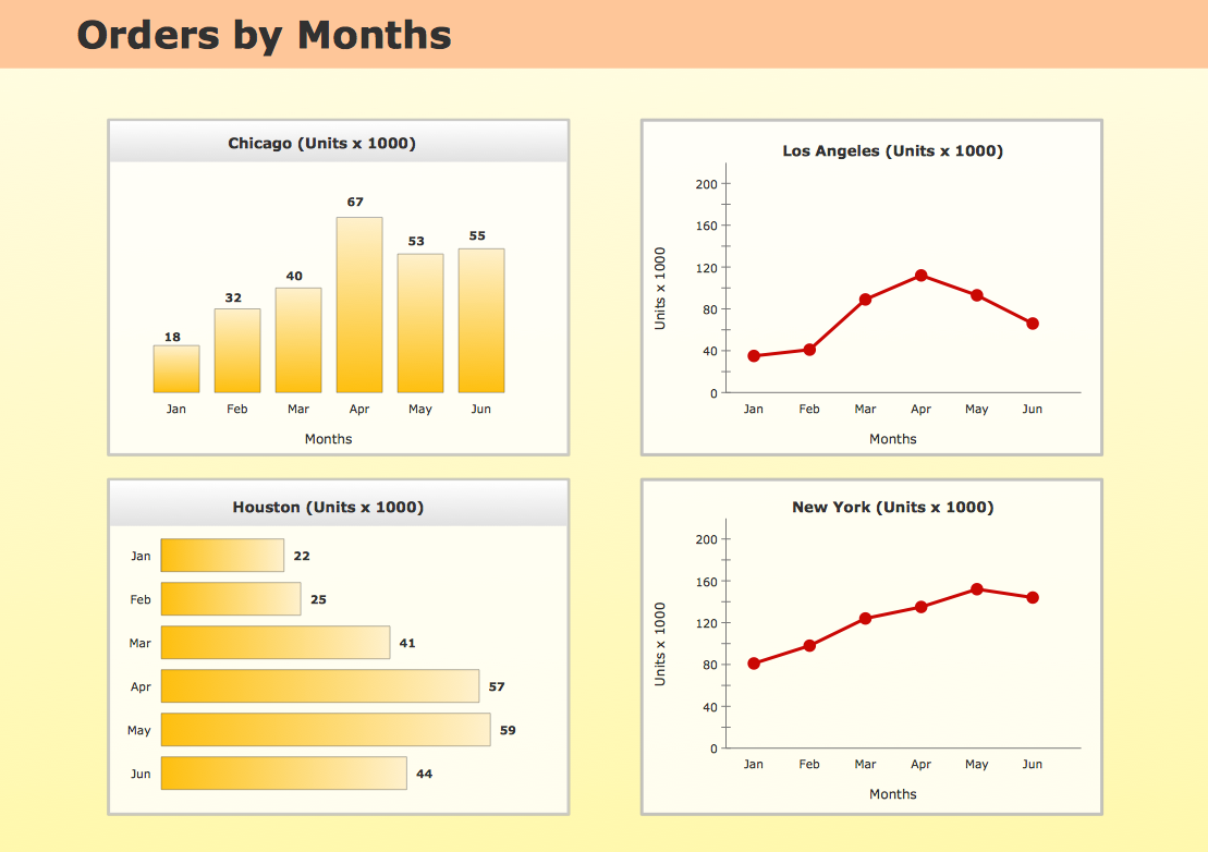
How to Create a Time Series Dashboard
Time Series Dashboard means integration of some type of diagrams: Line Charts, Bar Charts, Column Charts, and Dot Plots on a single space. The ConceptDraw Time Series Dashboard solution can be used to create the interactive Time Series dashboard. The libraries of Time Series Charts solution contain the Live Objects, that can change their appearance depending on the external data. Each chart from the Time Series dashboard displays particular source data. You can include Time Series Charts in your business or technical dashboards to show and compare the items changing over time.Databases Access Objects Model with ConceptDraw DIAGRAM
ConceptDraw Basic gives the opportunity of interaction with any ODBC-compatible databases. For this the Database Access Objects Model is provided. All calls to the database are made by certain methods of objects of this model.HelpDesk
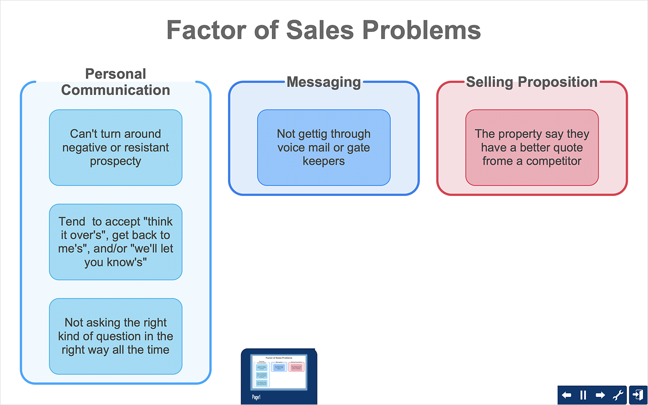
How To Create an Affinity Diagram Using Solutions
Affinity diagram is designed to prepare the data for further analysis of the cause-effect relationships.The Affinity diagram shows the structure of large, complex factors that have an influence on a problem, and then divides them up into a smaller and simpler structure. We recommend using a mind map for Brainstorming and collecting the factors affecting the problem. The ability to create an Affinity diagram from a mind map is supported by the ConceptDraw Seven Management and Planning Tools solution.Network Glossary Definition
The network glossary contains a complete list of network, computer-related and technical terms in alphabetic order, explanations and definitions for them, among them there are words well known for you and also specific, rare-used, uncommon or newly introduced terms. This specialized glossary, also known as a vocabulary, is the best in its field and covers in details the various aspects of computer network technologies. This glossary was developed by specialists using the practical experience and many useful sources to help the ConceptDraw users in their work, you can read and learn it from the screen on-line or print, it can be also used as a perfect educational guide or tutorial. ConceptDraw DIAGRAM software extended with Computer and Networks solution is easy to draw various types of Network diagrams, Network topology diagrams, Computer networking schematics, Network maps, Cisco network topology, Computer network architecture, Wireless networks, Vehicular networks, Rack diagrams, Logical, Physical, Cable networks, etc. Desktop ConceptDraw DIAGRAM Software is a good Visio for Mac Os X replacement. It gives you rich productivity and quality of the produced diagrams.
- Data Input Collection - Conceptdraw.com
- Data Input - Conceptdraw.com
- Data Output Collection - Conceptdraw.com
- Data - Vector stencils library
- Data - Vector stencils library - Conceptdraw.com
- ConceptDraw Solution Park | One formula of professional mind ...
- Business Process Elements: Data | Workflow Diagram Data | Types ...
- Example of DFD for Online Store ( Data Flow Diagram). DFD ...
- Design elements - Data Flow Diagram (DFD) | How to Create ...
- Interior Design Office Layout Plan Design Element | Design ...
- Order process - BPMN 2.0 diagram | Taxi service order procedure ...
- Group Collaboration Software | How To Successfully Hold a Group ...
- Data Flow Diagrams
- Flowchart - Product life cycle process | Flowchart - Project ...
- Business Process Modeling Software for Mac | Business Process ...
- One formula of professional mind mapping : input data + output data ...
- Logistics - Choreography BPMN 2.0 diagram | Design elements ...
- Data flow Model Diagram
- Word Exchange | One formula of professional mind mapping : input ...
- DFD - Process of account receivable | Data Flow Diagrams ...


