Network Diagramming with ConceptDraw PRO
At the moment computer networks are widespread, various types of computer networks are constructed around the world, operate and interact with each other. There are many kinds of computer networks that differ in the transmission medium, in communications protocols, in size, topology, organizational intent, and also in territorial basis. There are popular such types of computer networks as Global Area Network (GAN), Wide Area Network (WAN), Metropolitan Area Network (MAN), Local Area Network (LAN). ConceptDraw PRO is a powerful network diagramming software, perfect for software engineers, software designers and software developers who need to draw Computer Network diagrams, designs, schematics, and network maps in no time. The pre-drawn shapes representing computers, network devices and smart connectors offered by ConceptDraw solutions help to create the accurate diagrams and documentation, represent computer network topologies and designs, depict Computer network architectures, logical, physical, cable networks, and vehicular networks.The vector stencils library "Bank UML deployment diagram" contains 10 shapes for drawing UML deployment diagrams.
Use it for object-oriented modeling of your bank information system.
"A deployment diagram in the Unified Modeling Language models the physical deployment of artifacts on nodes. To describe a web site, for example, a deployment diagram would show what hardware components ("nodes") exist (e.g., a web server, an application server, and a database server), what software components ("artifacts") run on each node (e.g., web application, database), and how the different pieces are connected (e.g. JDBC, REST, RMI).
The nodes appear as boxes, and the artifacts allocated to each node appear as rectangles within the boxes. Nodes may have subnodes, which appear as nested boxes. A single node in a deployment diagram may conceptually represent multiple physical nodes, such as a cluster of database servers.
There are two types of Nodes:
1. Device Node.
2. Execution Environment Node.
Device nodes are physical computing resources with processing memory and services to execute software, such as typical computers or mobile phones. An execution environment node (EEN) is a software computing resource that runs within an outer node and which itself provides a service to host and execute other executable software elements." [Deployment diagram. Wikipedia]
This example of UML deployment diagram symbols for the ConceptDraw PRO diagramming and vector drawing software is included in the ATM UML Diagrams solution from the Software Development area of ConceptDraw Solution Park.
Product Overview
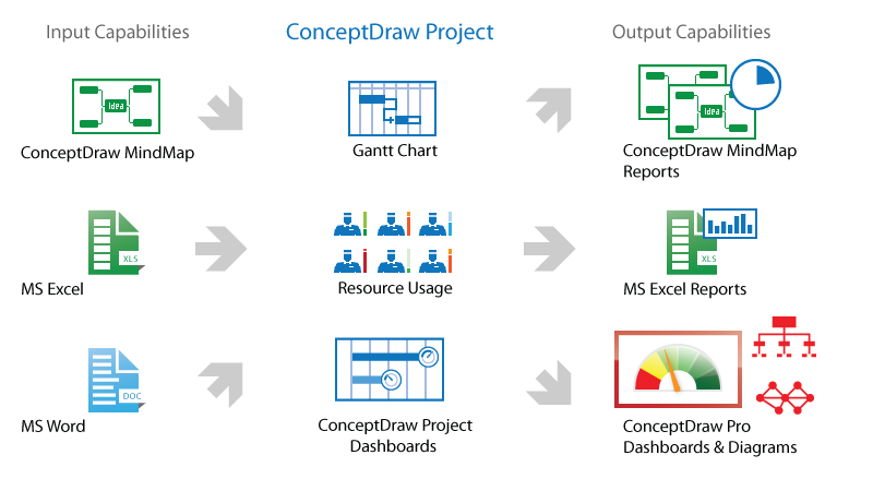
ConceptDraw PROJECT is a vigorous tool for managing single or multiple projects. It lets you determine all essential elements involved into project, control schedules, resources and finances, and monitor projects' progress in most effective yet simple manner.- Database Diagram Powerpoint
- UML Deployment Diagram Example
- Server hardware - Rack diagram | UML component diagram - Start ...
- Basic Flowchart Symbols and Meaning | Database Flowchart ...
- Entity Relationship Diagram For Library Management System
- Er Diagram For User Login
- ConceptDraw PRO ER Diagram Tool | UML Diagram | Entity ...
- Entity Relationship Diagram - ERD - Software for Design Crows Foot ...
- Process Flowchart | Flowchart Components | Basic Flowchart ...
- Entity Relationship Diagram - ERD - Software for Design Crows Foot ...
- Chen Notation | Design elements - ER diagram (Chen notation ...
- Components of ER Diagram | Process Flowchart | UML Deployment ...
- Components of ER Diagram | Stakeholder Management System ...
- Draw Component Diagram For Library Management System And
- Entity Relationship Diagram Symbols | ERD Symbols and Meanings ...
- UML Deployment Diagram . Design Elements | Design elements ...
- Entity-Relationship Diagram ( ERD )
- Components of ER Diagram | Process Flowchart | Network Glossary ...
- Component Diagrams For Web Hosting Sites
- Entity Relationship Diagram Symbols | HR Management Software ...


