 One-line Diagrams
One-line Diagrams solution is a powerful electrical engineering tool to develop precise and detailed One-line Diagram, Single-line Diagram, Electrical diagram. This solution supplies the ConceptDraw DIAGRAM users with a wide set of vector libraries with special icons and electrical symbol elements for one-line drawing and electrical engineering diagram design including. It includes a large collection of samples of One-line Diagrams illustrating high-voltage and low-voltage systems, different electrical configurations and topologies, transmission systems, application of circuit breakers, protection electrical equipment, etc. It is perfect for all power-related workers, engineers, electricians, and other professionals working in power engineering and energy industries.
 Power Сircuits
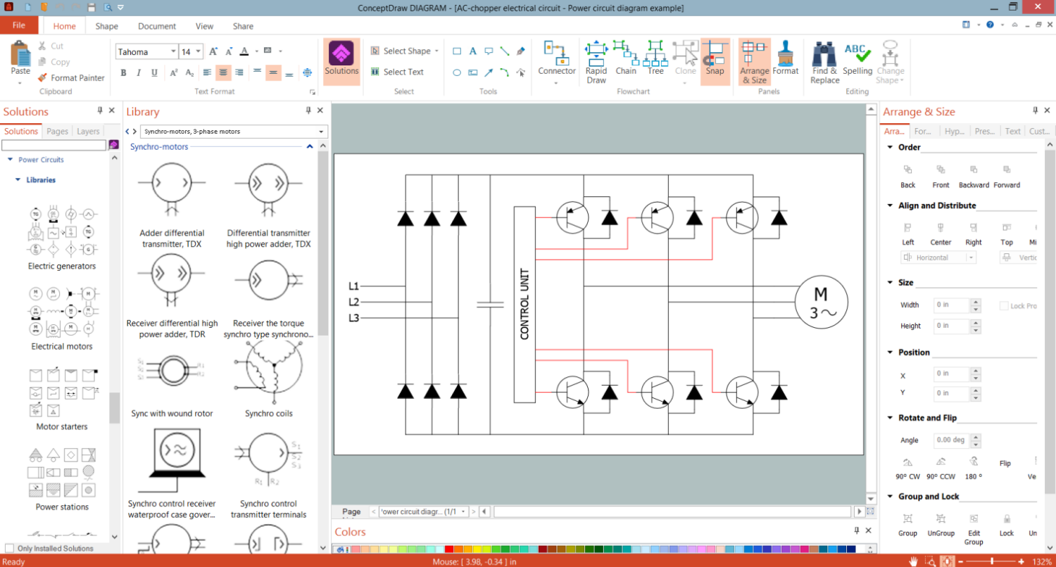
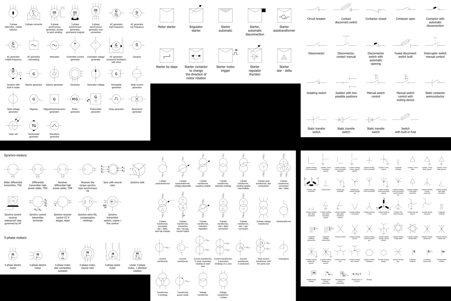
The Power Circuits solution for ConceptDraw DIAGRAM is designed for drawing power electrical circuits, power grids, power generation, transformation, transmission, and distribution systems. It includes a set of samples and a large number of generally accepted electrical circuit symbols that guarantee clarity and simple comprehension of diagrams. The electrical symbols of transformers, motor starters, power stations, electric generators, electrical motors, windings connections, transmission lines, and more equipment are included. Use this solution to successfully create the Power Circuit Diagram of any complexity, display the functional parts of the electrical circuit and connections between them, electrical connections in substations, explain the principles of operation of electrical and power mechanisms, one-phase and three-phase power generation, create specifications of power electrical equipment.
 Analog Electronics
The Analog Electronics solution extends ConceptDraw DIAGRAM with a set of samples and a collection of predesigned special objects and analog electronics symbols common for designing analog circuits. They include electrical signal connectors, transistors, semiconductors, diodes, sensors, transducers, thyristors, crystals, diacs, etc. This solution is incredibly helpful to construct analog electronic circuits, electronic engineering designs, electrical engineering diagrams and schematics of different complexity. This is incredibly useful for electrical engineers, electronics designers and developers, electricians, mechanics, and other electronics related professionals.
 Basic Circuit Diagrams
Basic Circuit Diagrams solution extends the functionality of ConceptDraw DIAGRAM application with a large variety of samples and internationally standardized electrical symbols and electrical circuit diagram symbols including resistor symbol, inductor, amplifier, relay, diode symbol, icons for electrical engineering equipment, electrical circuit instrumentation, active and passive components, digital electronics symbols. Use them to illustrate the electrical circuit of any kind and complexity in minutes, design electrical schematic, wiring diagram, electronic schematics, and more. This solution is effective for electrical engineers, architects, electricians, electrical technicians, builders, interior designers, and many more electricity-related specialists.
Electrical Circuit
An electrical circuit is a closed path created of conductive material. It establishes relationships between electrical source and load, and provides the flow of current or electricity. Circuit diagrams, Pictorial Diagrams, and Electric Circuit Schematics are visual ways to display electrical circuits to electricians or any other technical audience. ConceptDraw DIAGRAM software with the Power Сircuits solution includes plenty of standard electrical symbols and provides you the possibility to create clear, visual, and accurate Electrical Circuit diagrams and schematics in a few minutes. Electrical Diagram Symbols F.A.Q.How to Use Electrical ConceptDraw Diagram Software
When drawing Electrical Schematics, Electrical Circuit Diagrams, Power Systems Diagrams, Circuit and Wiring Diagrams, Digital and Analog Logic Schemes, you will obligatory need the electrical symbols and pictograms to represent various electrical and electronic devices, such as resistors, wires, transistors, inductors, batteries, switches, lamps, readouts, amplifiers, repeaters, relays, transmission paths, semiconductors, generators, and many more. Today these symbols are internationally standardized, so the diagrams designed using them are recognizable and comprehensible by specialists from different countries.
Electrical Engineering Solution included to ConceptDraw Solution Park provides 26 libraries with 926 commonly used electrical schematic and electrical engineering symbols making the reality the easy drawing of Electrical diagrams, schematics and blueprints. Now you need only a few minutes to create great-looking Electrical diagram, simply choose required electrical design elements from the libraries, drag them on the needed places at the document and connect in a suitable way.
Hybrid Network Topology
A network topology is the topological structure or the arrangement of different elements of computer network. There are several basic types of network topologies, such as star, ring, bus, mesh. But the most popular is a combination of two or more diverse basic network topologies, which is known as hybrid network topology. The examples of hybrid topology are: star-bus, star-ring topologies, etc. Each resulting hybrid topology has its own features, advantages and limitations of its components. Hybrid network topologies are more flexible, reliable, and have increased fault tolerance, the faults in them can be easily diagnosed and corrected, new nodes can be easily added. But at the same time hybrid topologies often are sufficiently expensive and difficult for managing. ConceptDraw DIAGRAM diagramming and vector drawing software supplied with the tools of Computer Network Diagrams solution from Computer and Networks area is perfect for schematic description various types of computer network topologies and easy designing Hybrid network topology diagrams.Diode Symbols
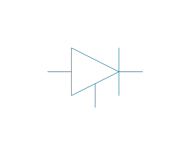
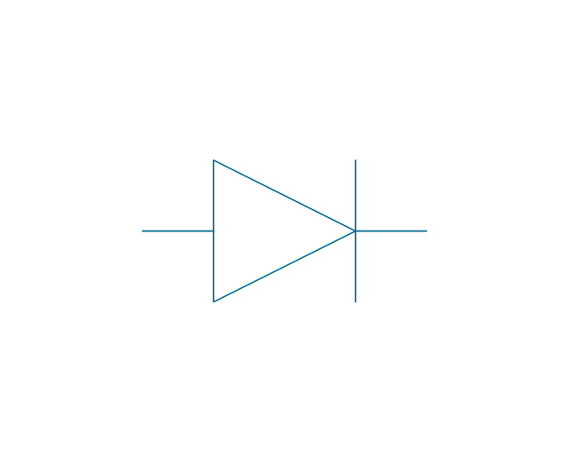
A diode is a semiconductor device that conducts electric current in only one direction. It can operate as a switch, a one-way valve for an electrical circuit, signal limiter, voltage regulator, or an insulator. The diode is a two-terminal electrical component, it includes two distinct electrodes: a negatively charged cathode and a positively charged anode. ConceptDraw DIAGRAM software extended with the Electron Tube Circuits solution is ideal for electrical engineering design and provides a variety of pre-made samples and a collection of predesigned vector symbols and clipart, including the diode symbol.Electric Generators
A generator is a device that converts mechanical energy obtained from an external source (fuel-based power) or kinetic energy into electric power or electricity as the output. ConceptDraw DIAGRAM software extended with the Power Сircuits solution is ideal for electrical engineering, development of electric generators and other electrical and electronic equipment. It includes a collection of predesigned vector design symbols and clipart for easy designing induction generator circuit diagram, schematic of double fed induction generator connected to a wind turbine, and many more other simple and complex generators.
 Green Energy
Green Energy solution extends the ConceptDraw DIAGRAM functionality with a large collection of vector design icons, pictograms, and clipart useful to design green energy infographics and illustrations of any kind. Create overview infographics about solar power, wind power, hydropower, tidal power and other renewable and cleaner energy sources. Compare visually different types of energy or data over several years in one chart. Develop detailed infographics about power generation mechanisms, how do solar panels work, wind and tidal turbines, and more specialized power generation equipment.
Block Diagram Creator
A block diagram is a diagram of a system in which the principal parts or functions are represented by blocks connected by lines that show the relationships of the blocks. ConceptDraw DIAGRAM diagramming and vector drawing software extended with Block Diagrams Solution from the "Diagrams" Area is a powerful Block Diagram Creator.
 Green Energy
Green Energy solution extends the ConceptDraw DIAGRAM functionality with a large collection of vector design icons, pictograms, and clipart useful to design green energy infographics and illustrations of any kind. Create overview infographics about solar power, wind power, hydropower, tidal power and other renewable and cleaner energy sources. Compare visually different types of energy or data over several years in one chart. Develop detailed infographics about power generation mechanisms, how do solar panels work, wind and tidal turbines, and more specialized power generation equipment.
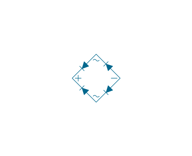
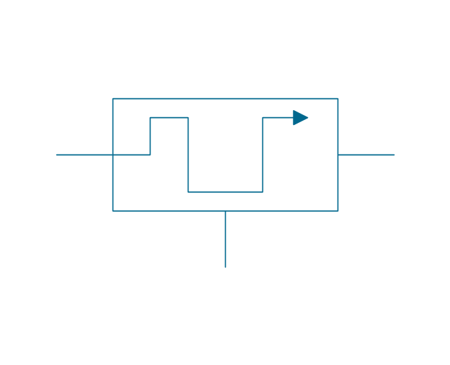
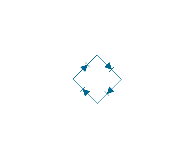
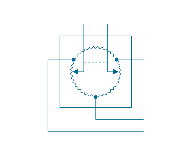
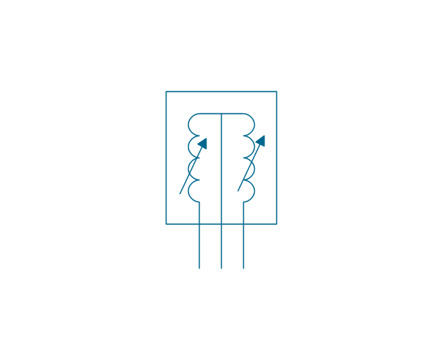
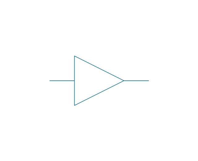
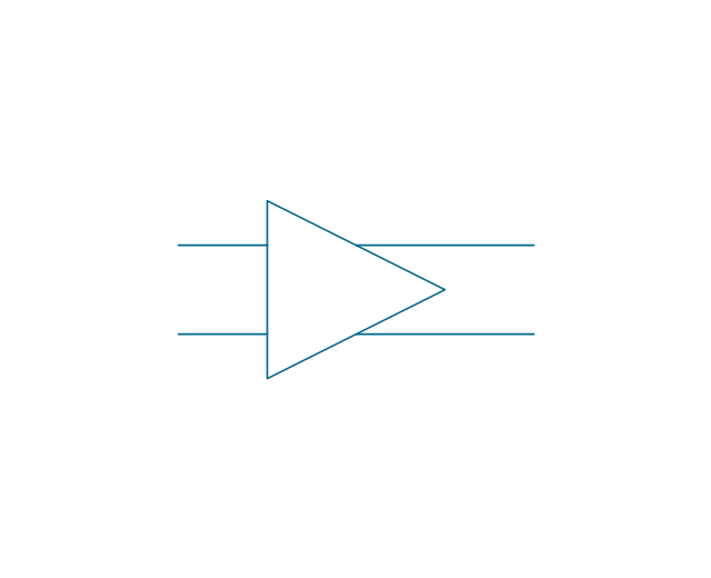
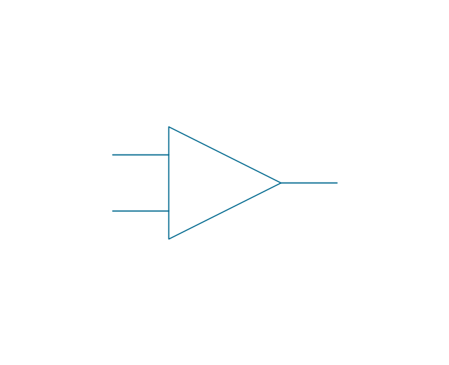
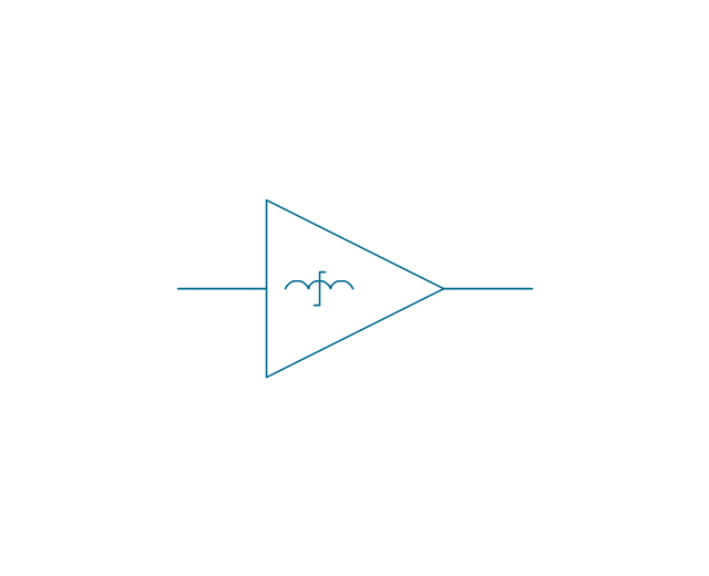
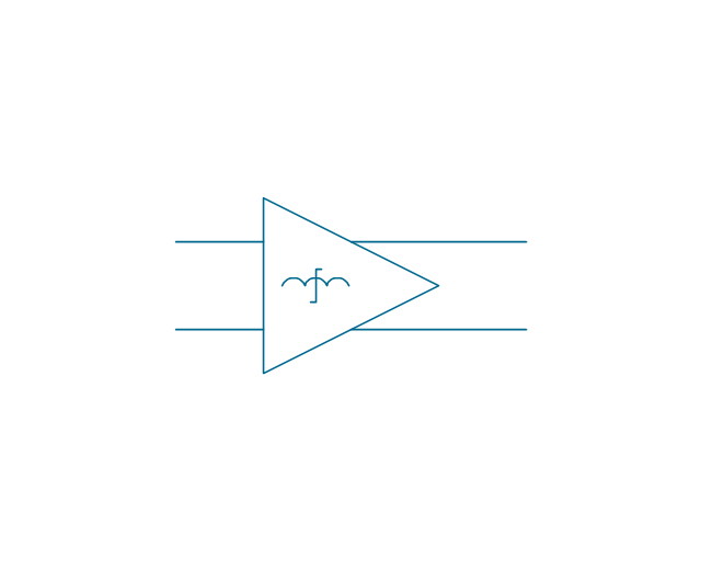
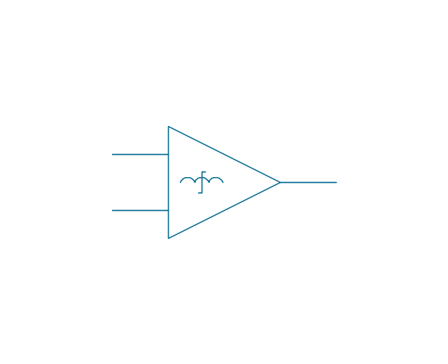
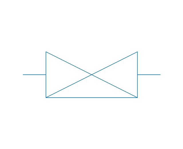
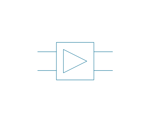
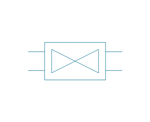
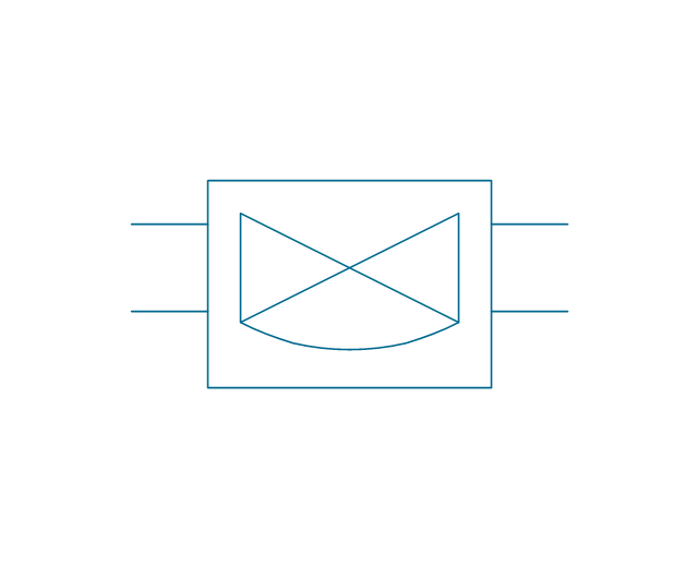
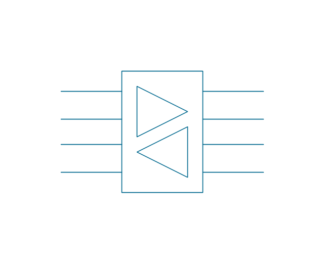
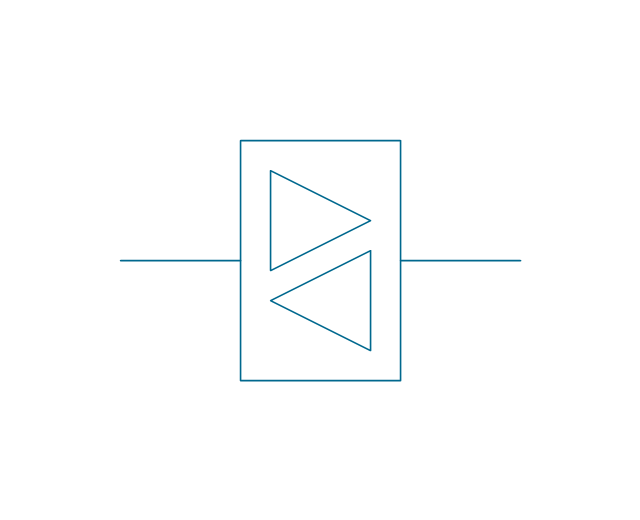
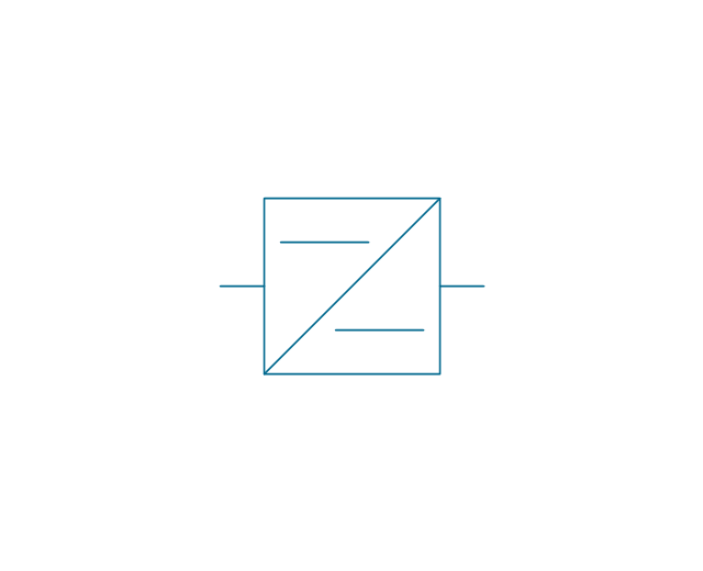
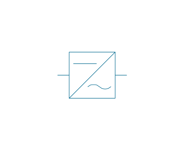
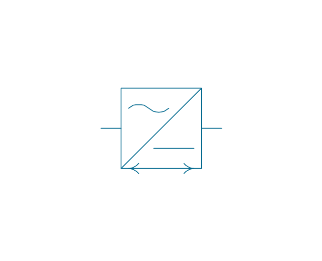
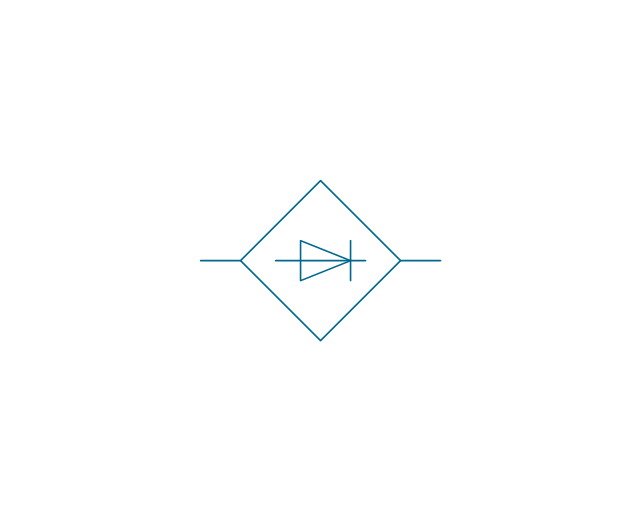
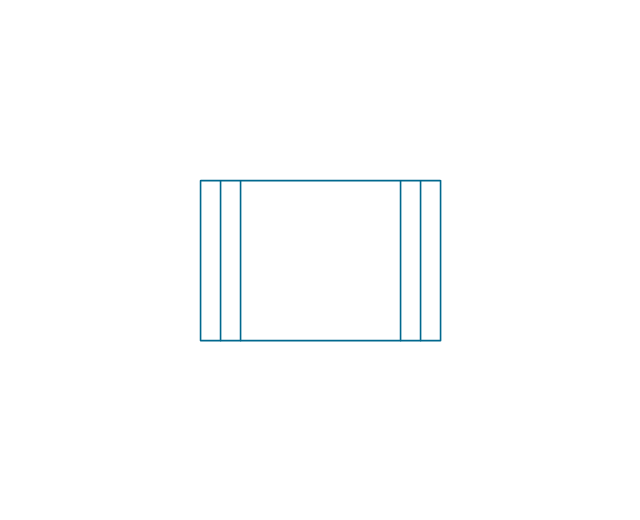
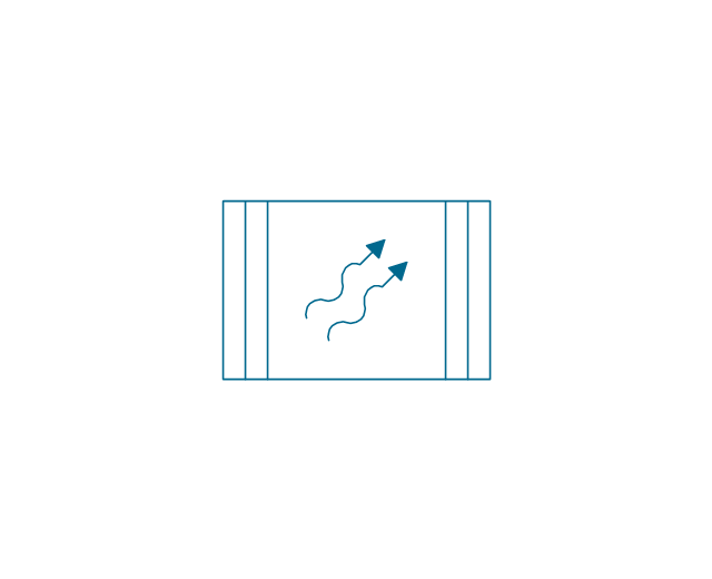
The vector stencils library "Composite assemblies" contains 44 element symbols of transmitters (electronic amplifiers, repeaters), static devices (rectifiers), phase shift circuits, gyroscopes, and gyrators.
Use it to design the electronic circuit diagrams and electrical schematics in the ConceptDraw PRO diagramming and vector drawing software extended with the Electrical Engineering solution from the Engineering area of ConceptDraw Solution Park.
www.conceptdraw.com/ solution-park/ engineering-electrical
Electrical Symbols — Rotating Equipment
Electrical rotating machines, such as motors and generators, are vital assets for any power plant or large industrial company. An electric motor is an electrical machine that converts electrical energy into mechanical energy. The reverse of this would be the conversion of mechanical energy into electrical energy and is done by an electric generator. In normal motoring mode, most electric motors operate through the interaction between an electric motor's magnetic field and winding currents to generate force within the motor. In certain applications, such as in the transportation industry with traction motors, electric motors can operate in both motoring and generating or braking modes to also produce electrical energy from mechanical energy. 26 libraries of the Electrical Engineering Solution of ConceptDraw DIAGRAM make your electrical diagramming simple, efficient, and effective. You can simply and quickly drop the ready-to-use objects from libraries into your document to create the electrical diagram.Circuit Symbols
The generally accepted and standardized representation of electronic symbols, signs, or pictograms allows creating of diagrams clear and understandable for all stakeholders. Power Circuits solution provides drawing packages with pre-made fundamental forms of different circuit symbols useful to create Electrical circuit diagrams, Electronic drawings, schematics, and layouts fast and easily. Use them to professionally and visually convey information about the arrangement of components and wiring. These diagrams are an essential part of the documentation for the development, use, and repair of electrical devices and appliances.Cisco Optical. Cisco icons, shapes, stencils and symbols
The ConceptDraw vector stencils library Cisco Optical contains symbols for drawing the computer network diagrams.Electrical Symbols, Electrical Schematic Symbols
Electrical Schematics and Electrical Circuit Diagrams are included to the number of obligatory diagrams and documents while developing the package of construction documentation for the building project. It is comfortable to use the special drawing software for designing diagrams of this type. ConceptDraw DIAGRAM diagramming and vector drawing software extended with Electrical Engineering solution from Industrial Engineering Area of ConceptDraw Solution Park provides the powerful drawing tools, a lot of specific samples and templates, and numerous libraries with incredibly large quantity of predesigned electrical schematic symbols, including analog and digital logic electrical symbols, electrical circuits symbols, inductors, power sources, lamps, resistors, transistors, delay elements, switches and relays, terminals and connectors, and many other useful electrical symbols, which will be helpful for easy designing professional looking Electrical Schematics, Electrical Engineering Diagrams, Circuit and Wiring Diagrams, Power Systems Diagrams, Digital and Analog Logic Schematics.Electrical Symbols — Composite Assemblies
Electronic components have two or more electrical terminals (or leads) aside from antennas which may only have one terminal. These leads connect to create an electronic circuit with a particular function (for example an amplifier, radio receiver, or oscillator). Basic electronic components may be packaged discretely, as arrays or networks of like components, or integrated inside of packages such as semiconductor integrated circuits, hybrid integrated circuits, or thick film devices. 26 libraries of the Electrical Engineering Solution of ConceptDraw DIAGRAM make your electrical diagramming simple, efficient, and effective. You can simply and quickly drop the ready-to-use objects from libraries into your document to create the electrical diagram.Electrical Symbols — Transistors
A transistor is a semiconductor device used to amplify or switch electronic signals and electrical power. It is composed of semiconductor material usually with at least three terminals for connection to an external circuit. A voltage or current applied to one pair of the transistor's terminals changes the current through another pair of terminals. Because the controlled (output) power can be higher than the controlling (input) power, a transistor can amplify a signal. Today, some transistors are packaged individually, but many more are found embedded in integrated circuits. 26 libraries of the Electrical Engineering Solution of ConceptDraw DIAGRAM make your electrical diagramming simple, efficient, and effective. You can simply and quickly drop the ready-to-use objects from libraries into your document to create the electrical diagram.
 Telecom and AV Circuits
Telecom and AV Circuits solution includes professionally designed samples and collection of pre-made vector elements of antennas, waveguides, antenna TV, audio, video, TV and telegraph equipment, etc. They assist in issues of automation, electrical engineering, designing schematics for amplifiers, receivers, TV audio video transmitters, telephone and radio circuits, making visualizations for telecommunication networks, wireless radio networks, layouts for the video systems. The solution tools help to present the innovations in telecommunications and AV, describe the construction of modern video and audio codecs, architectures and algorithms, specialized network protocols. Design efficiently the 3 way switch diagram, show the structure of a telecommunications network, its logic and configuration, transmit, receive and amplify audio and video signals.
- Design elements - Electrical circuits | Symbol Of Ideal Dc Voltage ...
- Voltage Controlled Current Source Visio
- Electrical Symbols — Inductors | Ac Voltage Symbol Visio
- Electrical Symbols — Power Sources | Electrical Symbols — Thermo ...
- Electrical Symbols — Power Sources | Power sources | Ac Dc Source
- Electrical Symbols — Power Sources | Functional Block Diagram ...
- Power sources - Vector stencils library
- Electrical Symbols — Power Sources | Car Battery Visio Stencil
- Electrical Symbols — Power Sources | Design elements - Power ...
- Visio Dc Motor - Electrical Diagram Symbols
