Bubble diagrams in Landscape Design with ConceptDraw DIAGRAM
To define the links between the different areas of your own landscape design and see the project from aside, we recommend to draw landscape diagram called bubble one which is analogue of «mind maps» as it allows us to create approximate image of our future proper landscape view. Use special libraries (and we have plenty of them) with objects of landscape design to be able to create the detailed plan of your landscape which will be looking so smart and professionally good as the samples we provide were created by designers who know so much about making such kinds of design plans. Having ConceptDraw DIAGRAM as the assistant in your work, will ensure the success after using our product. Make the bubble diagrams as well as any other ones in minutes with ease having our application called ConceptDraw DIAGRAM and you will see how quick it will change your life simplifying lots of work.
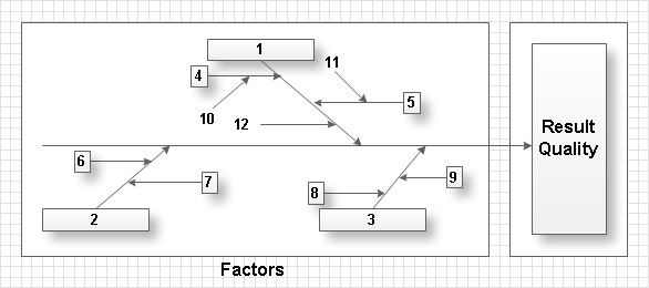
Total Quality Management with ConceptDraw
Total Quality Management (TQM) system is the management method where the confidence in quality of all organization processes is placed foremost. The given method is widely used in production, in educational system, in government organizations and so on.HelpDesk
ConceptDraw OFFICE for macOS Installation Definition
With the introduction of version 5, ConceptDraw OFFICE has been redesigned to better accommodate future developments and solution plugins. ConceptDraw OFFICE 5 includes ConceptDraw DIAGRAM 12, ConceptDraw MINDMAP 10, and ConceptDraw PROJECT 9. New ConceptDraw STORE helps a user manage downloads of ConceptDraw software and solutions. The following article provides owners of the previous versions of ConceptDraw products with important information on updating on ConceptDraw OFFICE 5.Event-driven Process Chain Diagrams
Event-Driven Process Chain Diagrams solution extends ConceptDraw DIAGRAM functionality with event driven process chain templates, samples of EPC engineering and modeling the business processes, and a vector shape library for drawing the EPC diagrams and EPC flowcharts of any complexity. It is one of EPC IT solutions that assist the marketing experts, business specialists, engineers, educators and researchers in resources planning and improving the business processes using the EPC flowchart or EPC diagram. Use the EPC solutions tools to construct the chain of events and functions, to illustrate the structure of a business process control flow, to describe people and tasks for execution the business processes, to identify the inefficient businesses processes and measures required to make them efficient.
HelpDesk
ConceptDraw OFFICE for Windows Installation Definition
With the introduction of version 5, ConceptDraw OFFICE has been redesigned to better accommodate future developments and solution plugins. ConceptDraw OFFICE 5 includes ConceptDraw DIAGRAM 12, ConceptDraw MINDMAP 10, and ConceptDraw PROJECT 9. New ConceptDraw STORE helps a user manage downloads of ConceptDraw software and solutions. The following article provides owners of the previous versions of ConceptDraw products with important information on updating on ConceptDraw OFFICE 5.IDEF0 Diagrams
IDEF0 Diagrams visualize system models using the Integration Definition for Function Modeling (IDEF) methodology. Use them for analysis, development and integration of information and software systems, and business process modelling.
HelpDesk
How to Create an Entity-Relationship Diagram
ERD (entity relationship diagram) is used to show the logical structure of databases. It represents the interrelationships between components of a database (entities). Entity relationship diagrams are widely used in software engineering. Using ERD software engineers can control every aspect of database development. ER diagram can be used as a guide for testing and communicating before the release of the software product. ERD displays data as entities that are connected with connections that show the relationships between entities. There are some ERD notations used by databases developers for representing the relationships between the data objects. ConceptDraw DIAGRAM and its ERD solution allow you to build ERD diagram of any notation.- Interior Design Site Plan - Design Elements | Design elements - Site ...
- Design elements - Lighting | Interior Design Site Plan - Design ...
- Building Drawing Design Element Site Plan | Landscape ...
- Interior Design Site Plan - Design Elements | Design elements - Site ...
- Design elements - Road signs | Interior Design Site Plan - Design ...
- Reflected Ceiling Plans | How to Create a Reflected Ceiling Floor ...
- Cafe and Restaurant Floor Plan | How To Create Restaurant Floor ...
- How To Create Restaurant Floor Plan in Minutes | Restaurant Floor ...
- Site Plans | How To use Appliances Symbols for Building Plan ...
- Network Layout Floor Plans | Cafe and Restaurant Floor Plan ...
- Design elements - Internal block diagram | Building Drawing ...
- Building Drawing Design Element Site Plan | How To use House ...
- How To Create Restaurant Floor Plan in Minutes | Cafe and ...
- Ground Floor Plan Definition
- Trees and plants - Vector stencils library | Interior Design Site Plan ...
- Electrical Drawing Software | Building Drawing Design Element Site ...
- Landscape Architecture with ConceptDraw PRO | Building Drawing ...
- Site Plans
- Office Layout | Entity Relationship Diagram Symbols and Meaning ...
- How To Create Restaurant Floor Plan in Minutes | Restaurant Floor ...
- ERD | Entity Relationship Diagrams, ERD Software for Mac and Win
- Flowchart | Basic Flowchart Symbols and Meaning
- Flowchart | Flowchart Design - Symbols, Shapes, Stencils and Icons
- Flowchart | Flow Chart Symbols
- Electrical | Electrical Drawing - Wiring and Circuits Schematics
- Flowchart | Common Flowchart Symbols