 Object-Role Modeling (ORM) Diagrams
Object-role Modeling (ORM) Diagram solution with powerful vector diagramming and data modeling tools, large quantity of specially developed samples and examples, and rich variety of vector objects corresponding to common ORM notation, ideally suits for developing the comprehensive, clear and visual Object-role Modeling (ORM) diagrams and schematics, understandable for all interested people from the different fields and business directions, for designing the ORM models, and demonstrating advantages from the use of ORM and its notation. It is intended for software developers and computer engineers, specialists in a field of Object-oriented programming (OOP), database architects, web-application constructors and developers, etc.
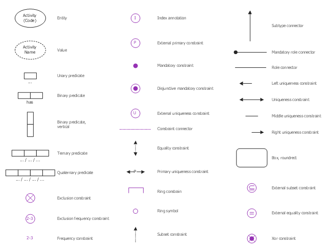
The vector stencils library "ORM diagram" contains 32 object-role modeling (ORM) notation symbols.
Use it to design your ORM diagrams with ConceptDraw PRO software in data modeling and software engineering.
The vector stencils example "Design elements - ORM diagram" is included in ORM Diagrams solution from Software Development area of ConceptDraw Solution Park.
Use it to design your ORM diagrams with ConceptDraw PRO software in data modeling and software engineering.
The vector stencils example "Design elements - ORM diagram" is included in ORM Diagrams solution from Software Development area of ConceptDraw Solution Park.
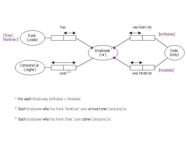
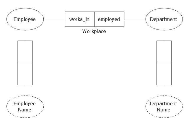
This object-role modeling (ORM) diagram sample shows model of employee data: birthdate, hiredate, rank, company car number. It was designed on the base of the Wikimedia Commons file: ORM-diagram-tkz-orm.png. [commons.wikimedia.org/ wiki/ File:ORM-diagram-tkz-orm.png]
"Facts.
Object-role models are based on elementary facts, and expressed in diagrams that can be verbalised into natural language. ...
This "fact-based" approach facilitates modeling, transforming, and querying information from any domain. ...
Attribute-free.
ORM is attribute-free: unlike models in the entity–relationship (ER) and Unified Modeling Language (UML) methods, ORM treats all elementary facts as relationships and so treats decisions for grouping facts into structures (e.g. attribute-based entity types, classes, relation schemes, XML schemas) as implementation concerns irrelevant to semantics. By avoiding attributes in the base model, ORM improves semantic stability and enables verbalization into natural language. ...
Fact-based modeling.
Fact-based modeling includes procedures for mapping facts to attribute-based structures, such as those of ER or UML. ...
Fact-based graphical notations are more expressive than those of ER and UML. ...
Design procedure.
System development typically involves several stages such as: feasibility study; requirements analysis; conceptual design of data and operations; logical design; external design; prototyping; internal design and implementation; testing and validation; and maintenance." [Object-role modeling. Wikipedia]
The object-role modeling diagram example "Employee ORM diagram" was designed using ConceptDraw PRO software extended with ORM Diagrams solution from Software Development area of ConceptDraw PRO Solution Park.
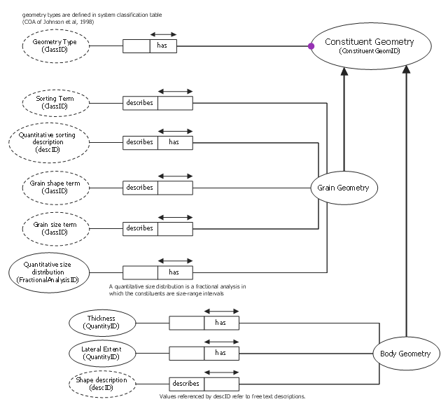
This object-role modeling (ORM) diagram sample shows schema for constituent geometry. It was designed on the base of the Wikimedia Commons file: Schema for Constituent Geometry.gif. [commons.wikimedia.org/ wiki/ File:Schema_ for_ Constituent_ Geometry.gif]
"Constituent Geometry... models a data structure for describing the geometry of individual constituents in a Particular Lithology. These descriptions are based on terms that may have qualitative or quantitative definitions (e.g. round, subround, euhedral, subhedral, fine-grained) or on free text descriptions referenced by "descID'. The Constituent Geometry description has two sub-classes, Grain Geometry and Body Geometry, because different terminology is used when describing individual grains or lithologic components in a mixed rock." [pubs.usgs.gov/ of/ 1999/ of99-386/ richard.html]
The object-role modeling diagram example "Constituent geometry ORM diagram" was designed using ConceptDraw PRO software extended with ORM Diagrams solution from Software Development area of ConceptDraw PRO Solution Park.
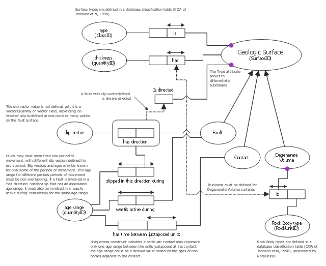
This object-role modeling (ORM) diagram sample shows schema for geologic surface.
It was designed on the base of the Wikimedia Commons file: Schema for Geologic Surface.svg. [commons.wikimedia.org/ wiki/ File:Schema_ for_ Geologic_ Surface.svg]
This file is made available under the Creative Commons CC0 1.0 Universal Public Domain Dedication. [creativecommons.org/ publicdomain/ zero/ 1.0/ deed.en]
"The Geologic Surface ... schema requires that a Geologic Surface have a type attribute that determines the subclass membership for the surface, and an attribute that indicates if the surface is directed. A characteristic Thickness of the surface may also be defined. Fault surfaces have associated Slip Vectors that record displacements across the fault. A Fault may have several associated slip vectors if displacement is known to have changed over time. Faults and Contacts both have associated Age Ranges. For a Fault, the age range is the time interval during which the fault was active. For active faults, the lower bound of this range is 0. Faults may have more than one associated age range to allow for more than one period of activity. Distinct age ranges may be related to distinct slip vectors to record the full displacement history of a Fault. The age range associated with Contacts represents the time interval that separates rocks on either side of the Contact. Only one age range may be associated with a Contact. Degenerate Volumes are entities used to represent descriptions of a discrete layer or a boundary layers that is too thin at the scale of representation to depict on a map. Examples include soil profiles, dikes, veins, fault rocks, and marker beds. A Degenerate Volume surface is associated with a Rock Unit classification object that describes the lithologic characteristics of the material in the boundary layer. A thickness must be defined for a Degenerate Volume surface." [pubs.usgs.gov/ of/ 1999/ of99-386/ richard.html]
The object-role modeling diagram example "Geologic surface ORM diagram" was designed using ConceptDraw PRO software extended with ORM Diagrams solution from Software Development area of ConceptDraw PRO Solution Park.
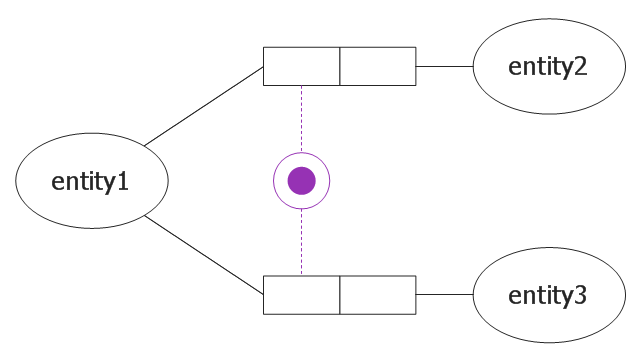
This object-role modeling (ORM) diagram sample shows disjunctive mandatory role constraint.
It was designed on the base of the Wikimedia Commons file: 9 DisjunktyvusPrivalomumoRibojimas.jpg. [commons.wikimedia.org/ wiki/ File:9_ DisjunktyvusPrivalomumoRibojimas.jpg]
"2.7. Mandatory Role Constraints.
The ORM 1 tool indicates simple mandatory constraints by a solid dot either (a) at the intersection of an entity type shape and the line connecting it to a role, or (b) at the role end. Option (b) is needed to avoid ambiguity when an object type plays many mandatory roles whose connections to the object type are too close to distinguish which role the dot applies to. Currently, disjunctive mandatory (inclusive-or) constraints are depicted by placing the solid dot in a circle connected by dotted lines to the roles it applies to. ORM 2 retains this notation, except that the solid dot is consistently colored violet and a global configuration option determines the default placement of simple mandatory dots at the role or object type end. Users may override this global setting on an individual role basis." [www.orm.net/ pdf/ ORM2_ TechReport1.pdf]
The object-role model example "Disjunctive mandatory constraint ORM diagram" was designed using ConceptDraw PRO software extended with ORM Diagrams solution from Software Development area of ConceptDraw PRO Solution Park.
This object-role modeling (ORM) diagram sample was designed on the base of the Wikimedia Commons file: Orm modell beispiel.gif. [commons.wikimedia.org/ wiki/ File:Orm_ modell_ beispiel.gif]
"Object-role Modeling (ORM) is a fact-oriented modeling approach for expressing, transforming and querying information at a conceptual level. Unlike Entity-Relationship modeling and Unified Modeling Language class diagramming, fact-oriented modeling is attribute-free, treating all elementary facts as relationships expressed in natural language sentences. For information modeling, ORM graphical notations are typically far more expressive than other notations, and ORM’s attribute-
free nature promotes semantic stability and facilitates natural verbalization." [www.orm.net/ pdf/ ORM2_ TechReport1.pdf]
The object-role model example "Object role modeling example" was designed using ConceptDraw PRO software extended with ORM Diagrams solution from Software Development area of ConceptDraw PRO Solution Park.
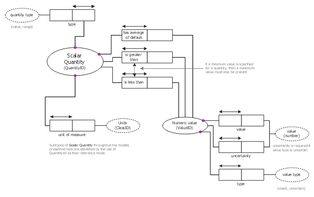
This object-role modeling (ORM) diagram sample shows schema for scalar quantity.
It was designed on the base of the Wikimedia Commons file: Schema for Scalar Quantity.gif. [commons.wikimedia.org/ wiki/ File:Schema_ for_ Scalar_ Quantity.gif]
"Scalar Quantities (Figure 2) are used throughout the model to specify numerical values. The Scalar Quantity concept modeled here allows several representations. The simplest is "quantity has a single numeric value and a measurement unit attribute'. Possible more complex representations include a single value with an uncertainty, or a minimum and maximum value with a specified default value to use if a single value representation is required. In all cases the Scalar Quantity has a specified unit of measurement attribute. Subtypes of Scalar Quantity in other Figures are identified by the use of QuantityID as the reference mode for a subtype entity." [pubs.usgs.gov/ of/ 1999/ of99-386/ richard.html]
The object-role model example "Scalar quantity ORM diagram" was designed using ConceptDraw PRO software extended with ORM Diagrams solution from Software Development area of ConceptDraw PRO Solution Park.
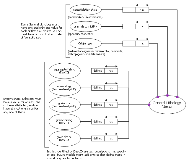
This object-role modeling (ORM) diagram sample shows schema for general lithology.
It was designed on the base of the Wikimedia Commons file: Schema for General Lithology.gif. [commons.wikimedia.org/ wiki/ File:Schema_ for_ General_ Lithology.gif]
"The General Lithology schema (Figure 4) models the structure of a lithology type definition. These definitions provide the logical foundation for classification of rocks into general lithologic classes. A geologic information system should contain a basic set of clearly defined lithologic terms in a standard classification table. ...
The General Lithology may have widely varying degrees of specificity. The most general types are defined on only one aspect of the lithology -- e.g. sandstone, mudstone, schist." [pubs.usgs.gov/ of/ 1999/ of99-386/ richard.html]
The object-role modeling diagram example "General lithology ORM diagram" was designed using ConceptDraw PRO software extended with ORM Diagrams solution from Software Development area of ConceptDraw PRO Solution Park.
