- Electric and Telecom Plans Free
- Fire and Emergency Plans Free
- Floor Plans Free
- Plant Layout Plans Free
- School and Training Plans Free
- Seating Plans Free
- Security and Access Plans Free
- Site Plans Free
- Sport Field Plans Free
- Business Process Diagrams Free
- Business Process Mapping Free
- Classic Business Process Modeling Free
- Cross-Functional Flowcharts Free
- Event-driven Process Chain Diagrams Free
- IDEF Business Process Diagrams Free
- Logistics Flow Charts Free
- Workflow Diagrams Free
- ConceptDraw Dashboard for Facebook Free
- Mind Map Exchange Free
- MindTweet Free
- Note Exchange Free
- Project Exchange Free
- Social Media Response Free
- Active Directory Diagrams Free
- AWS Architecture Diagrams Free
- Azure Architecture Free
- Cisco Network Diagrams Free
- Cisco Networking Free
- Cloud Computing Diagrams Free
- Computer Network Diagrams Free
- Google Cloud Platform Free
- Interactive Voice Response Diagrams Free
- Network Layout Floor Plans Free
- Network Security Diagrams Free
- Rack Diagrams Free
- Telecommunication Network Diagrams Free
- Vehicular Networking Free
- Wireless Networks Free
- Comparison Dashboard Free
- Composition Dashboard Free
- Correlation Dashboard Free
- Frequency Distribution Dashboard Free
- Meter Dashboard Free
- Spatial Dashboard Free
- Status Dashboard Free
- Time Series Dashboard Free
- Basic Circle-Spoke Diagrams Free
- Basic Circular Arrows Diagrams Free
- Basic Venn Diagrams Free
- Block Diagrams Free
- Concept Maps Free
- Family Tree Free
- Flowcharts Free
- Basic Area Charts Free
- Basic Bar Graphs Free
- Basic Divided Bar Diagrams Free
- Basic Histograms Free
- Basic Line Graphs Free
- Basic Picture Graphs Free
- Basic Pie Charts Free
- Basic Scatter Diagrams Free
- Aerospace and Transport Free
- Artwork Free
- Audio, Video, Media Free
- Business and Finance Free
- Computers and Communications Free
- Holiday Free
- Manufacturing and Maintenance Free
- Nature Free
- People Free
- Presentation Clipart Free
- Safety and Security Free
- Analog Electronics Free
- Audio and Video Connectors Free
- Basic Circuit Diagrams Free
- Chemical and Process Engineering Free
- Digital Electronics Free
- Electrical Engineering Free
- Electron Tube Circuits Free
- Electronic Block Diagrams Free
- Fault Tree Analysis Diagrams Free
- GHS Hazard Pictograms Free
- Home Automation and Wiring Free
- Mechanical Engineering Free
- One-line Diagrams Free
- Power Сircuits Free
- Specification and Description Language (SDL) Free
- Telecom and AV Circuits Free
- Transport Hazard Pictograms Free
- Data-driven Infographics Free
- Pictorial Infographics Free
- Spatial Infographics Free
- Typography Infographics Free
- Calendars Free
- Decision Making Free
- Enterprise Architecture Diagrams Free
- Fishbone Diagrams Free
- Organizational Charts Free
- Plan-Do-Check-Act (PDCA) Free
- Seven Management and Planning Tools Free
- SWOT and TOWS Matrix Diagrams Free
- Timeline Diagrams Free
- Australia Map Free
- Continent Maps Free
- Directional Maps Free
- Germany Map Free
- Metro Map Free
- UK Map Free
- USA Maps Free
- Customer Journey Mapping Free
- Marketing Diagrams Free
- Matrices Free
- Pyramid Diagrams Free
- Sales Dashboard Free
- Sales Flowcharts Free
- Target and Circular Diagrams Free
- Cash Flow Reports Free
- Current Activities Reports Free
- Custom Excel Report Free
- Knowledge Reports Free
- MINDMAP Reports Free
- Overview Reports Free
- PM Agile Free
- PM Dashboards Free
- PM Docs Free
- PM Easy Free
- PM Meetings Free
- PM Planning Free
- PM Presentations Free
- PM Response Free
- Resource Usage Reports Free
- Visual Reports Free
- House of Quality Free
- Quality Mind Map Free
- Total Quality Management TQM Diagrams Free
- Value Stream Mapping Free
- Astronomy Free
- Biology Free
- Chemistry Free
- Language Learning Free
- Mathematics Free
- Physics Free
- Piano Sheet Music Free
- Android User Interface Free
- Class Hierarchy Tree Free
- Data Flow Diagrams (DFD) Free
- DOM Tree Free
- Entity-Relationship Diagram (ERD) Free
- EXPRESS-G data Modeling Diagram Free
- IDEF0 Diagrams Free
- iPhone User Interface Free
- Jackson Structured Programming (JSP) Diagrams Free
- macOS User Interface Free
- Object-Role Modeling (ORM) Diagrams Free
- Rapid UML Free
- SYSML Free
- Website Wireframe Free
- Windows 10 User Interface Free
Object-Role Modeling (ORM) Diagrams
Object-role Modeling (ORM) is a methodology of conceptual projecting the informational systems and designing the database models, introduced in the 1970s. Since that time, the ORM technology is widely used for the data modeling and software engineering, for modeling the business rules, data warehouses, XML schemas, engineering requirements, as well as in web programming when developing the different kinds of web applications. It allows linking the database to the concepts of object-oriented programming, creating a "virtual object database", where the objects represent the objects from a real world. The Object-role Modeling lets model the systems and to depict them in a simple and compact form in terms of objects (entities and values), their roles, and relationships between them.
The ORM, which is also the modern method and technique of programming, lets transform the incompatible data types in object-oriented programming languages. It is effective when exchanging the data with relational database and contributes to simplifying the process of saving objects to the relational database, and their subsequent extraction. At this when extracting the objects, their properties and relationships between them are completely stored.
The ORM semantic modeling method is successfully used for the conceptual analysis of the business rules, the ORM structure is recognized as the most stable in conditions of changes in the business. The ORM can be used both independently and in conjunction with other methods of data modeling and software engineering. The use of Object-role Modeling approach allows creating the sustainable schematics and diagrams to depict the data model in a compact, clear and visual form. Besides, the ORM uses the own special graphical notation, which lets make diagrams, understandable for all interested people, even without technical education. It lets classify the objects into the entities and values, which according to the ORM notation are displayed using the solid and dashed ellipses, to set their roles, associations, references, relationships, etc.
Object-role Modeling (ORM) Diagrams solution extends the ConceptDraw DIAGRAM software functionality with powerful vector diagramming and data modeling tools, large quantity of specially developed samples and examples, and rich variety of vector objects corresponding to common ORM notation, which are convenient for using when developing the comprehensive, clear and visual Object-role Modeling (ORM) diagrams and schematics, designing the ORM models, and demonstrating advantages from the use of ORM and its notation. Developed according to the ORM concept, the Object-role Modeling (ORM) Diagrams solution is intended for all software developers and computer engineers, specialists in a field of Object-oriented programming (OOP), database architects, web-application constructors and developers. Besides, due to the use of common notation the resulting diagrams will be understandable for all interested people from the different fields and business directions.
-
Install this solution Free -
What I need to get started -
Solution Requirements - This solution requires the following products to be installed:
ConceptDraw DIAGRAM v18 - This solution requires the following products to be installed:
-
Compatibility - Sonoma (14), Sonoma (15)
MS Windows 10, 11 - Sonoma (14), Sonoma (15)
-
Support for this Solution -
Helpdesk
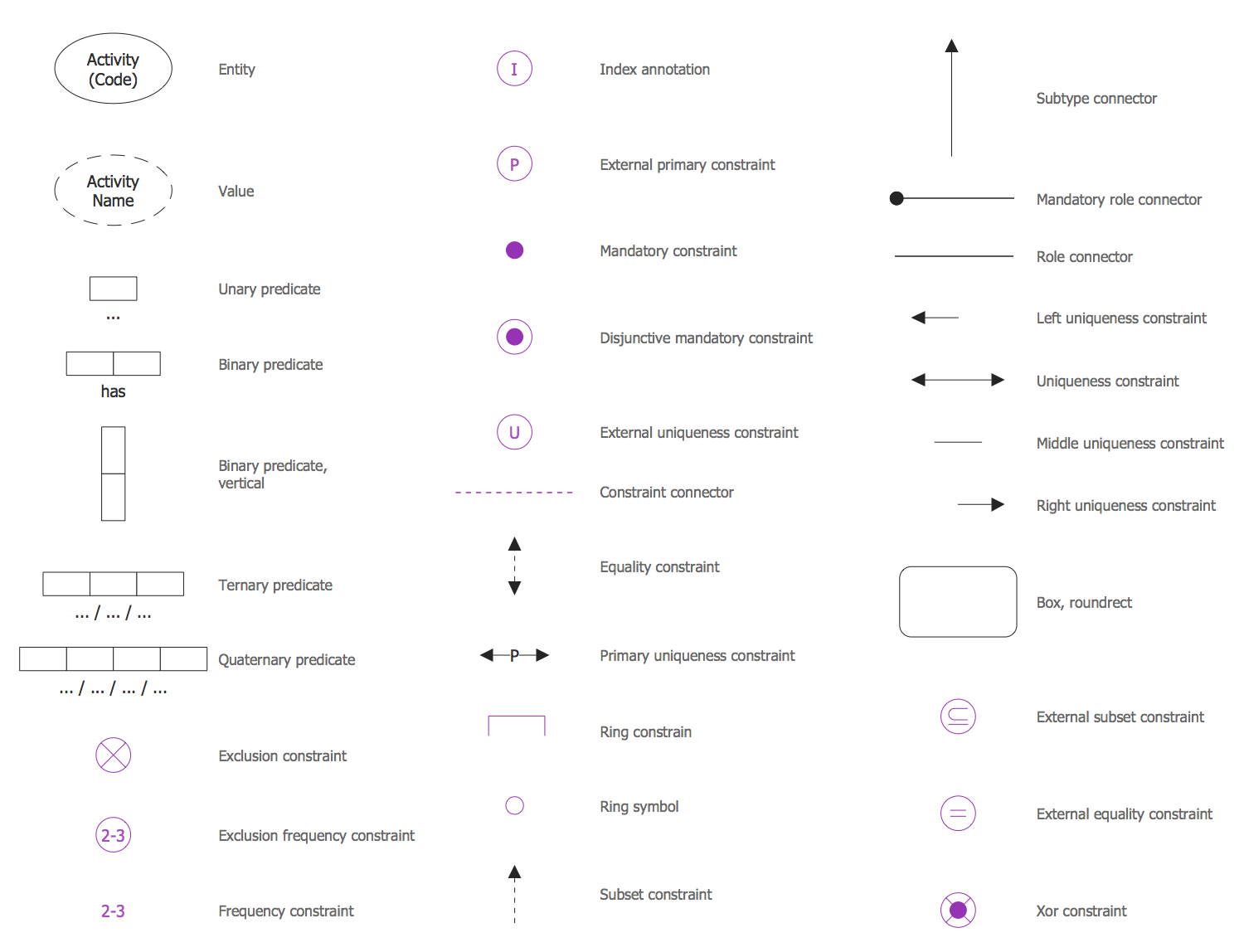
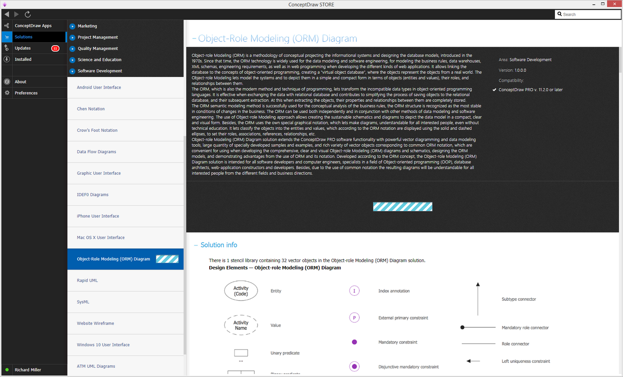
Design Elements — Object-role Modeling (ORM) Diagram
Examples
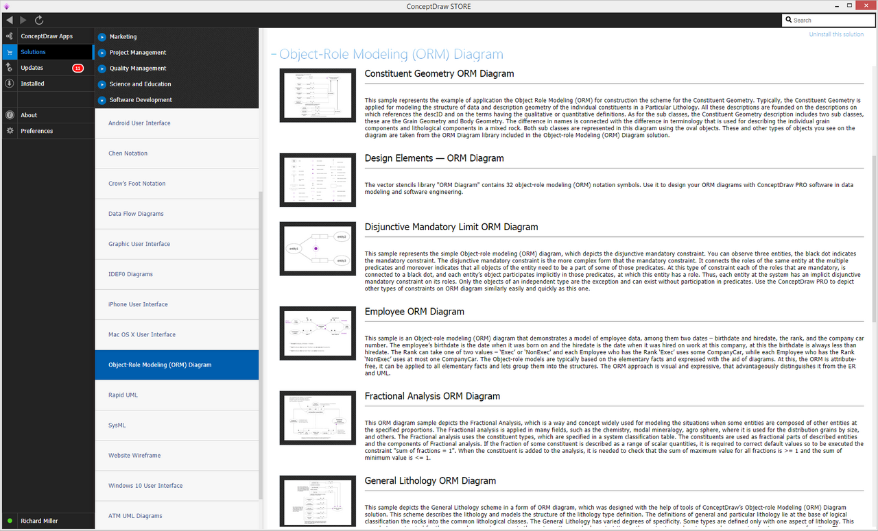
There are a few samples that you see on this page which were created in the ConceptDraw DIAGRAM application by using the Object-role Modeling (ORM) Diagrams solution. Some of the solution's capabilities as well as the professional results which you can achieve are all demonstrated here on this page.
All source documents are vector graphic documents which are always available for modifying, reviewing and/or converting to many different formats, such as MS PowerPoint, PDF file, MS Visio, and many other graphic ones from the ConceptDraw Solution Park or ConceptDraw STORE. The Object-role Modeling (ORM) Diagrams solution is available to all ConceptDraw DIAGRAM users to get installed and used while working in the ConceptDraw DIAGRAM diagramming and drawing software.
Example 1: Constituent Geometry ORM Diagram
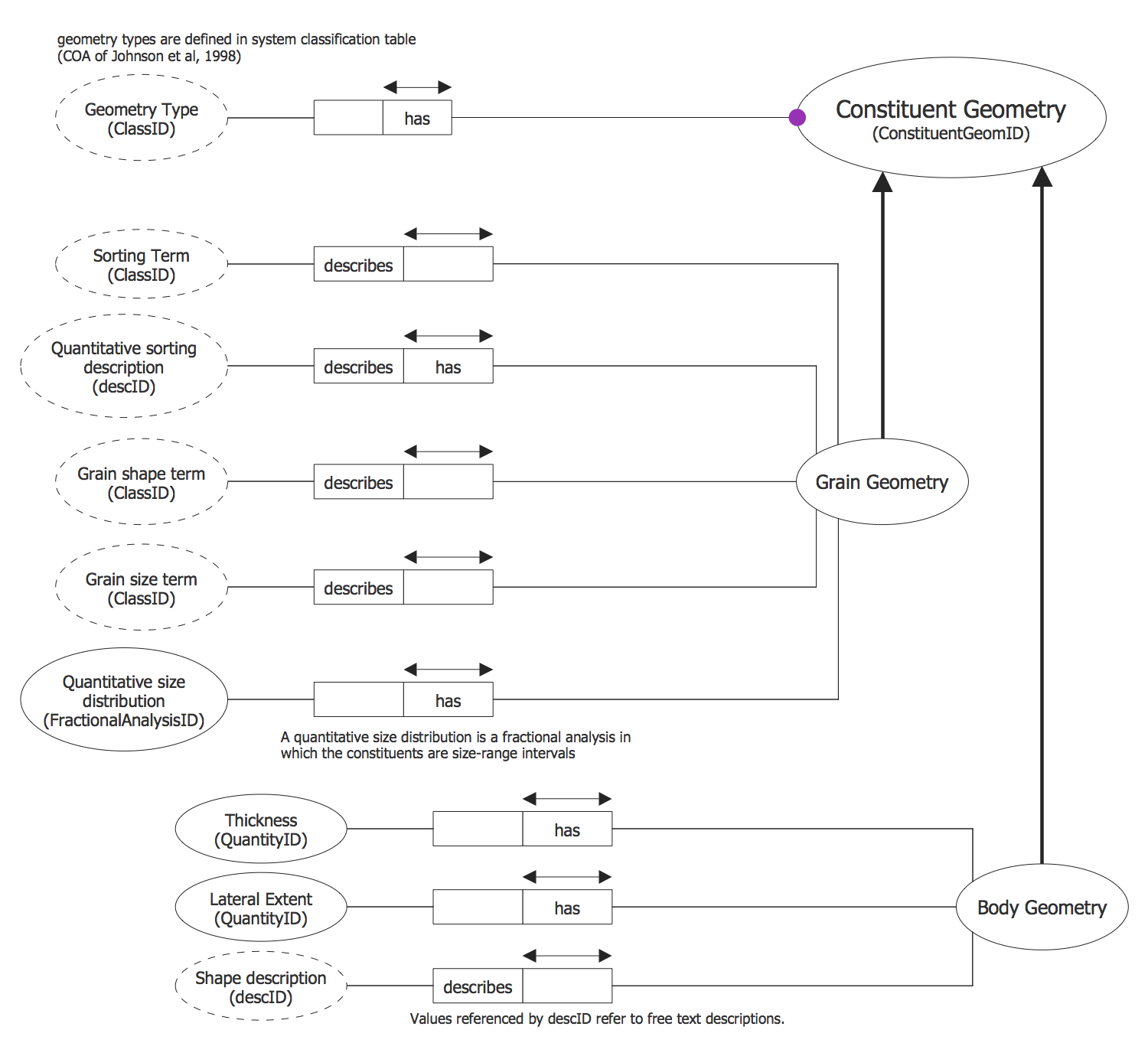
This diagram was created in ConceptDraw DIAGRAM using the Object-role Modeling (ORM) Diagram library from the Object-role Modeling (ORM) Diagrams Solution. An experienced user spent 10 minutes creating this sample.
This sample represents the example of application the Object Role Modeling (ORM) for construction the scheme for the Constituent Geometry. Typically, the Constituent Geometry is applied for modeling the structure of data and description geometry of the individual constituents in a Particular Lithology. All these descriptions are founded on the descriptions on which references the descID and on the terms having the qualitative or quantitative definitions. As for the sub classes, the Constituent Geometry description includes two sub classes, these are the Grain Geometry and Body Geometry. The difference in names is connected with the difference in terminology that is used for describing the individual grain components and lithological components in a mixed rock. Both sub classes are represented in this diagram using the oval objects. These and other types of objects you see on the diagram are taken from the ORM Diagrams library included in the Object-role Modeling (ORM) Diagrams solution.
Example 2: Disjunctive Mandatory Limit ORM Diagram
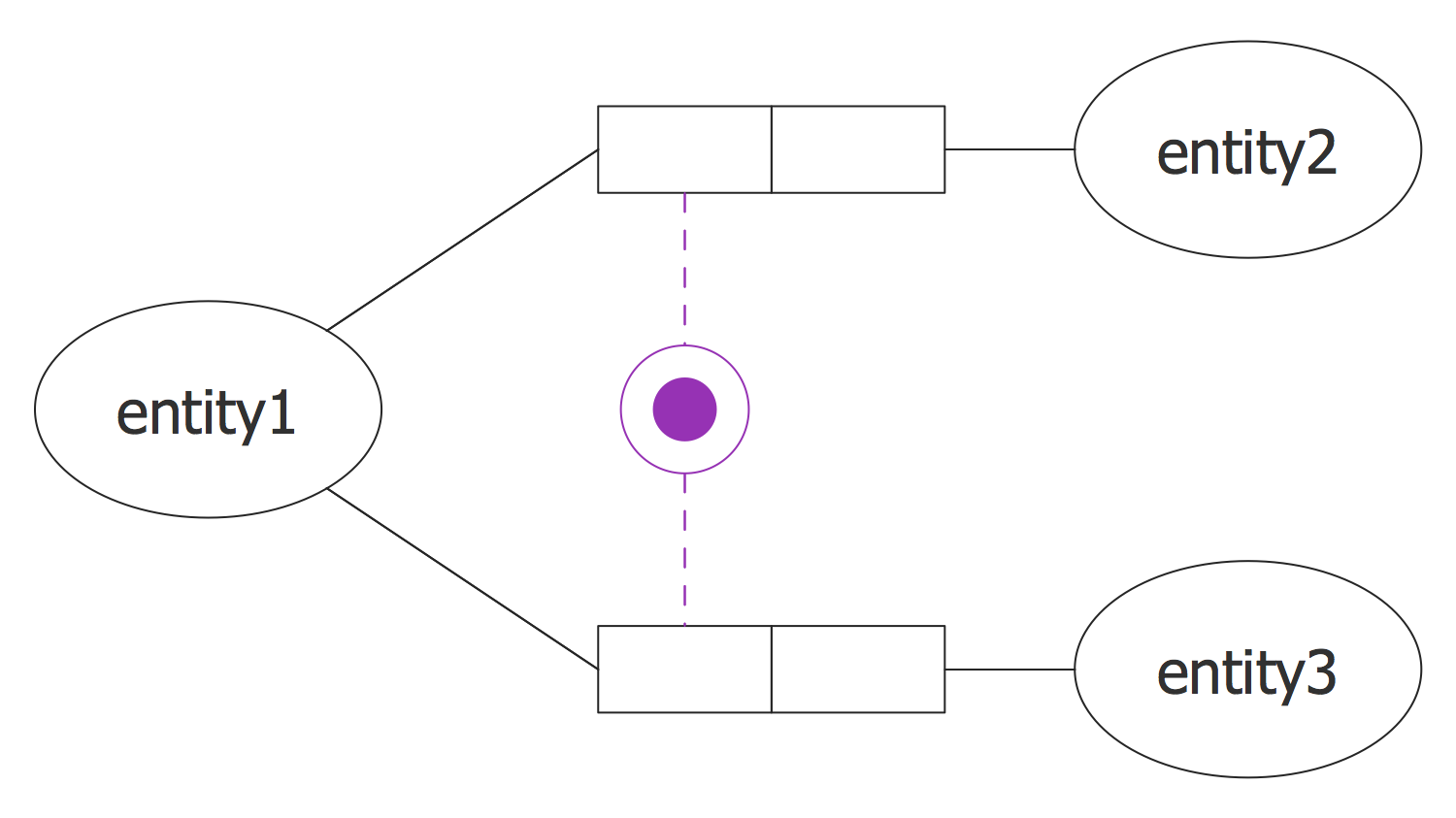
This diagram was created in ConceptDraw DIAGRAM using the Object-role Modeling (ORM) Diagram library from the Object-role Modeling (ORM) Diagrams Solution. An experienced user spent 3 minutes creating this sample.
This sample represents the simple Object-role modeling (ORM) diagram, which depicts the disjunctive mandatory constraint. You can observe three entities, the black dot indicates the mandatory constraint. The disjunctive mandatory constraint is the more complex form that the mandatory constraint. It connects the roles of the same entity at the multiple predicates and moreover indicates that all objects of the entity need to be a part of some of those predicates. At this type of constraint each of the roles that are mandatory, is connected to a black dot, and each entity's object participates implicitly in those predicates, at which this entity has a role. Thus, each entity at the system has an implicit disjunctive mandatory constraint on its roles. Only the objects of an independent type are the exception and can exist without participation in predicates. Use the ConceptDraw DIAGRAM to depict other types of constraints on ORM diagram similarly easily and quickly as this one.
Example 3: Employee ORM Diagram
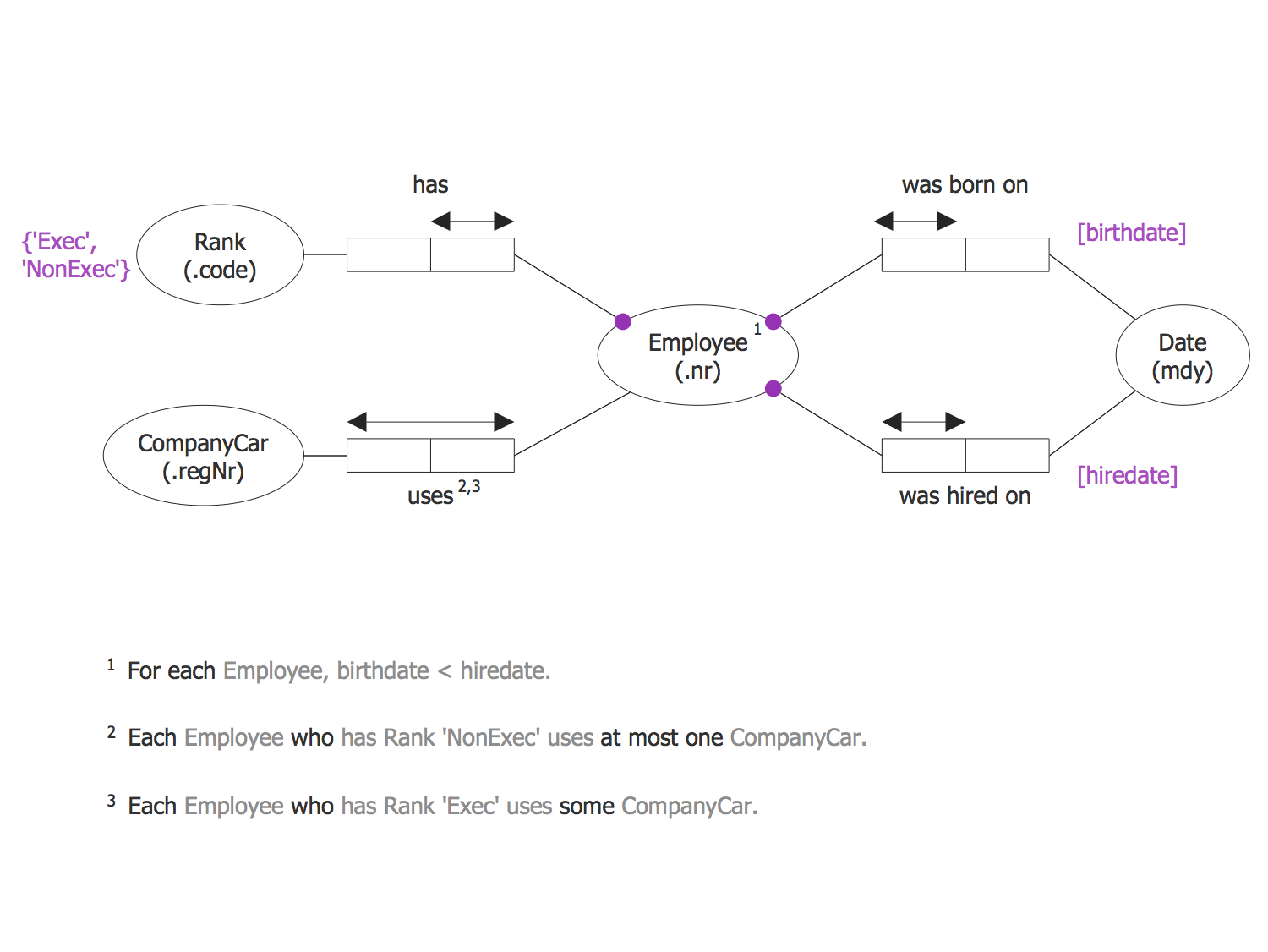
This diagram was created in ConceptDraw DIAGRAM using the Object-role Modeling (ORM) Diagram library from the Object-role Modeling (ORM) Diagrams Solution. An experienced user spent 5 minutes creating this sample.
This sample is an Object-role modeling (ORM) diagram that demonstrates a model of employee data, among them two dates – birthdate and hiredate, the rank, and the company car number. The employee's birthdate is the date when it was born on and the hiredate is the date when it was hired on work at this company, at this the birthdate is always less than hiredate. The Rank can take one of two values – ‘Exec’ or ‘NonExec’ and each Employee who has the Rank ‘Exec’ uses some CompanyCar, while each Employee who has the Rank ‘NonExec’ uses at most one CompanyCar. The Object-role models are typically based on the elementary facts and expressed with the aid of diagrams. At this, the ORM is attribute-free, it can be applied to all elementary facts and lets group them into the structures. The ORM approach is visual and expressive, that advantageously distinguishes it from the ER and UML.
Example 4: Fractional Analysis ORM Diagram
This diagram was created in ConceptDraw DIAGRAM using the Object-role Modeling (ORM) Diagram library from the Object-role Modeling (ORM) Diagrams Solution. An experienced user spent 10 minutes creating this sample.
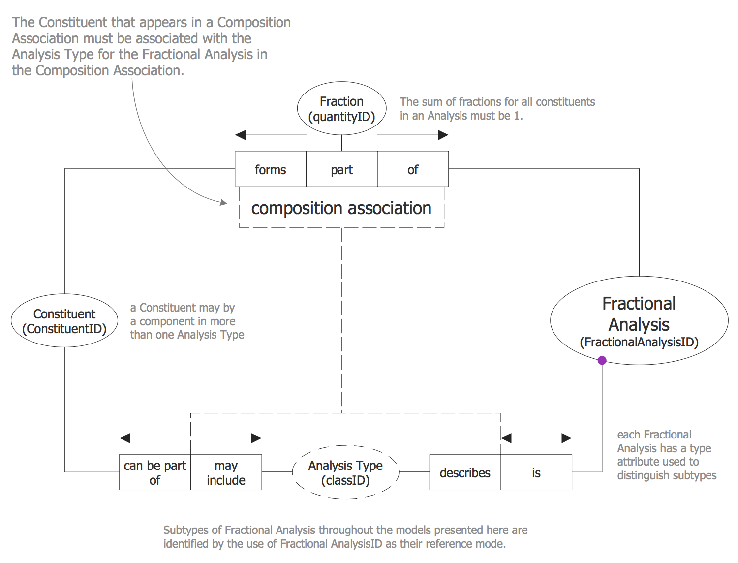
This ORM diagram sample depicts the Fractional Analysis, which is a way and concept widely used for modeling the situations when some entities are composed of other entities at the specified proportions. The Fractional analysis is applied in many fields, such as the chemistry, modal mineralogy, agro sphere, where it is used for the distribution grains by size, and others. The Fractional analysis uses the constituent types, which are specified in a system classification table. The constituents are used as fractional parts of described entities and the components of Fractional analysis. If the fraction of some constituent is described as a range of scalar quantities, it is required to correct default values so to be executed the constraint "sum of fractions = 1". When the constituent is added to the analysis, it is needed to check that the sum of maximum value for all fractions is >= 1 and the sum of minimum value is <= 1.
Example 5: General Lithology ORM Diagram
This diagram was created in ConceptDraw DIAGRAM using the Object-role Modeling (ORM) Diagram library from the Object-role Modeling (ORM) Diagrams Solution. An experienced user spent 15 minutes creating this sample.
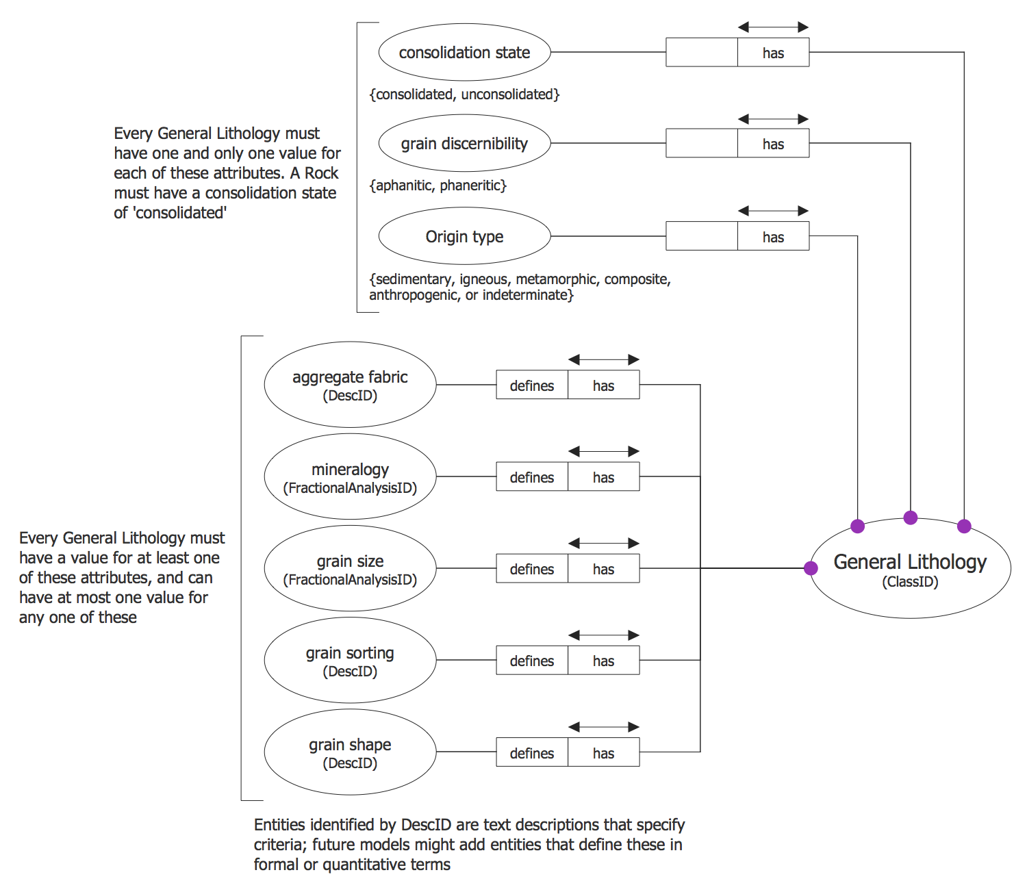
This sample depicts the General Lithology scheme in a form of ORM diagram, which was designed with the help of tools of ConceptDraw's Object-role Modeling (ORM) Diagrams solution. This scheme describes the lithology and models the structure of the lithology type definition. The definitions of general and particular lithology lie at the base of logical classification the rocks into the common lithological classes. The General Lithology has varied degrees of specificity. Some types are defined only with one aspect of lithology. This sample is constructed for the agro sphere and represents the grain sorting, such characteristics as the grain size and grain shape have great value in a process of sorting. There are listed the attributes on this diagram sample and every General lithology must have one and only one value for each attribute from the first group and a value for at least one of attributes from the second group.
Example 6: Geologic Surface ORM Diagram
This diagram was created in ConceptDraw DIAGRAM using the Object-role Modeling (ORM) Diagram library from the Object-role Modeling (ORM) Diagrams Solution. An experienced user spent 15 minutes creating this sample.
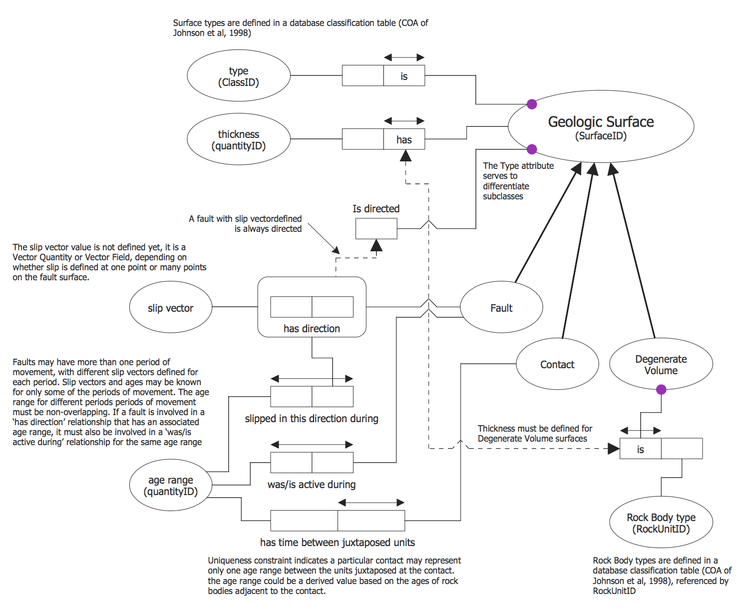
This Object-role modeling (ORM) diagram example shows the scheme for the Geologic Surface. The Geologic Surface (SurfaceID) object is the main on this scheme. It needs to have the type attribute determining the subclass membership for the surface, the attribute indicating if the surface is directed or not, as well as such characteristics as the thickness of the surface, slip vectors, age range can be also defined. The slip vectors are associated with fault surfaces, moreover, the surface can have several slip vectors, which let define the displacements respecting the fault. The age ranges are inherent and associated with Faults and Contacts, at this the Faults can have more than one associated age range, but only one age range can be associated with a Contact. You can also see the Degenerate Volume object on this diagram, which represents the entities describing the discrete or boundary layers, and is associated with a Rock Body type (RockUnitID) object.
Example 7: Object-Role Modeling Example
This diagram was created in ConceptDraw DIAGRAM using the Object-role Modeling (ORM) Diagram library from the Object-role Modeling (ORM) Diagrams Solution. An experienced user spent 5 minutes creating this sample.
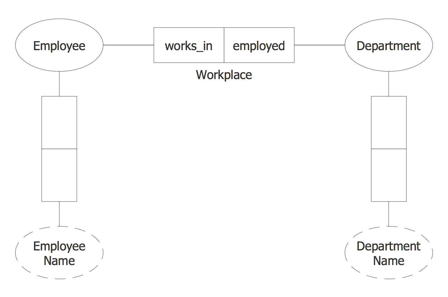
This sample represents the Object-Role Modeling example designed in ConceptDraw DIAGRAM software with the use of ORM notation objects offered by the Object-role Modeling (ORM) Diagrams library from the Object-role Modeling (ORM) Diagrams Solution. The ORM is a data modeling language, which is widespread for modeling different systems in terms of system's objects and the roles played by them, for software engineering and designing relational databases. You can see in this diagram two objects Employee and Department represented by the solid ellipse objects, which are the main components of the modeled system, the values Employee Name and Department Name represented by the dashed ellipses, the vertical binary predicates and the Workplace binary predicate, in which the entities play the indicated two roles 'works_in' and 'employed'. Using the predesigned vector ORM objects from the offered ConceptDraw's Object-role Modeling (ORM) Diagrams library you can design both simple Object-role Modeling diagrams and complex with many objects.
Example 8: Object-Role Model Overview
This diagram was created in ConceptDraw DIAGRAM using the Object-role Modeling (ORM) Diagram library from the Object-role Modeling (ORM) Diagrams Solution. An experienced user spent 20 minutes creating this sample.
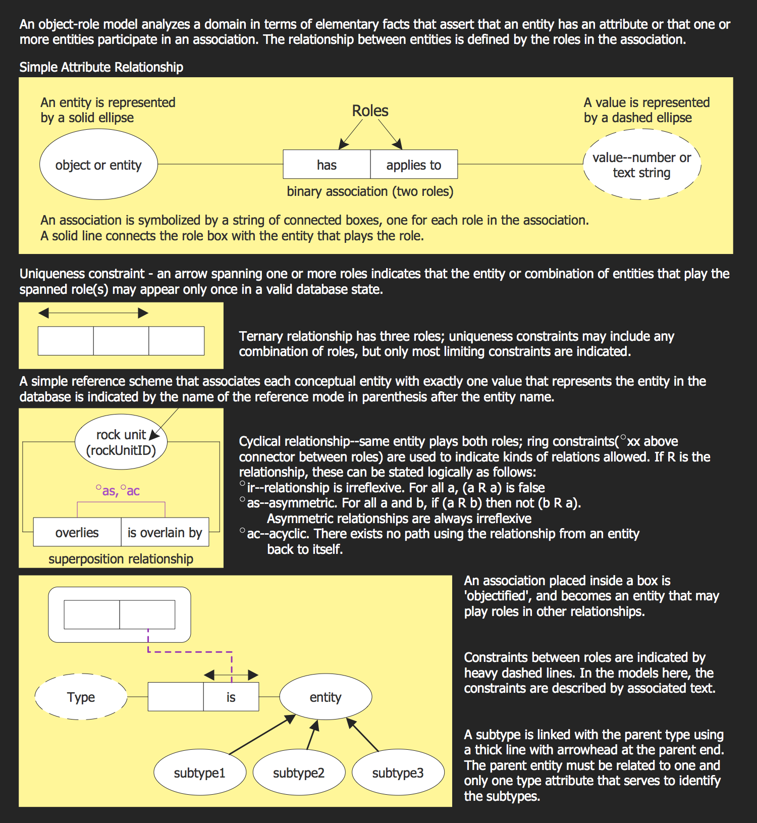
This ORM diagram sample represents the object-role model overview with a detailed description of ORM semantics - the special graphical symbols and notations, concepts and all composition elements used for construction the ORM diagrams. The ORM notation uses such types of objects as an ellipse for representing the entity, dashed ellipse for representing a value, single, double and triple rectangles for representing different types of predicates, arrows to represent the constraints, and many other symbols, which let make the most detailed ORM diagram. The Object-role modeling (ORM) technology is successfully used for modeling the business rules, for designing the XML schematics, for graphical representation and description the conceptual models, the data warehouses, engineering requirements and web forms. The ORM is incredibly convenient for describing the aspects of different domains of science due to the expressiveness of representing information and clearness of description the concepts and techniques applied for realization the ORM conceptual models.
Example 9: Particular Lithology ORM Diagram
This diagram was created in ConceptDraw DIAGRAM using the Object-role Modeling (ORM) Diagram library from the Object-role Modeling (ORM) Diagrams Solution. An experienced user spent 15 minutes creating this sample.
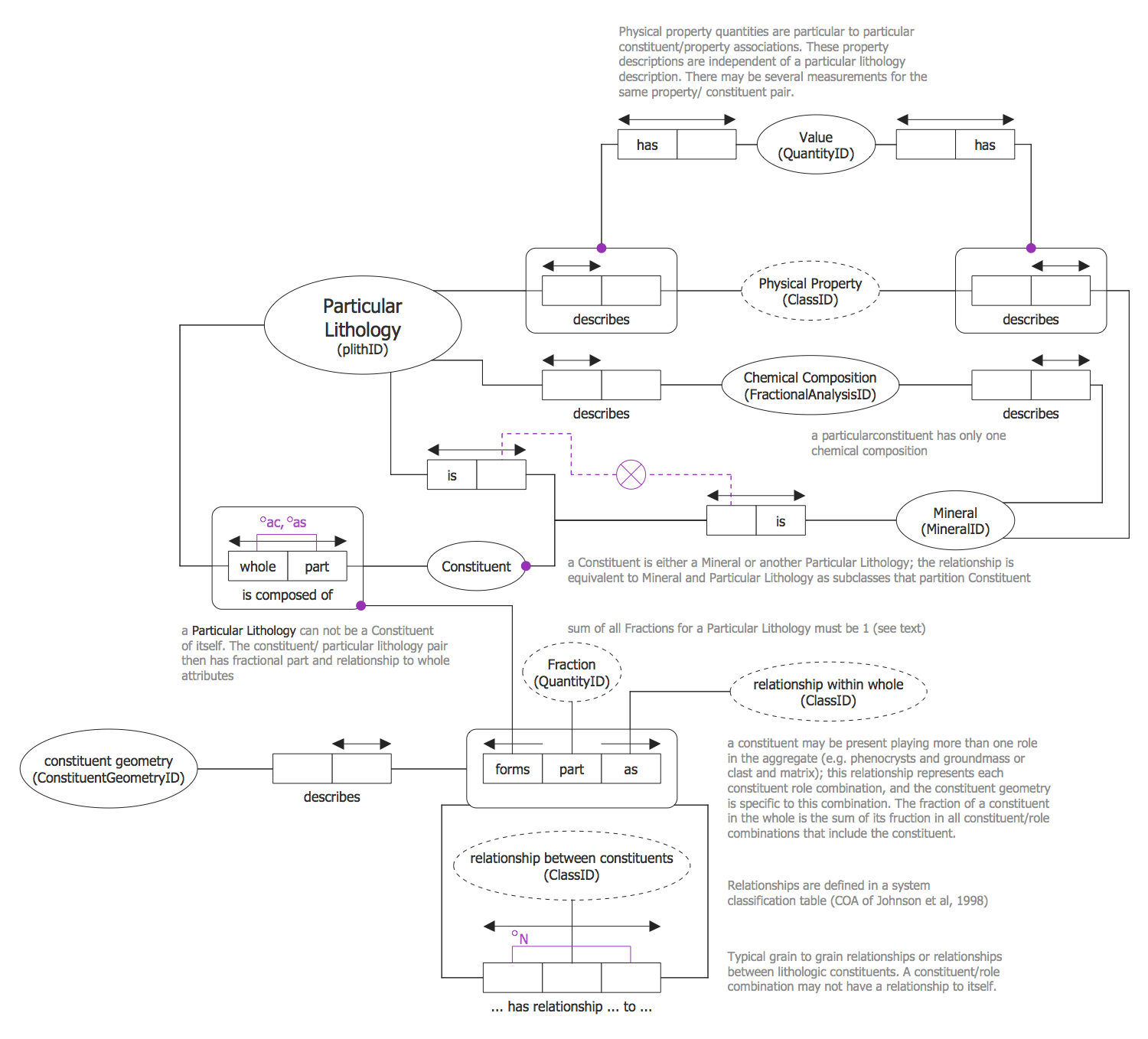
This Object-role Modeling Diagram sample represents the scheme for the Particular Lithology. It was constructed to model the concept of lithology and to descript the particular rock. The Particular Lithology is modeled as the totality of constituents and represents the set of entities associated with General Lithology. The Particular Lithology entities are used to describe the rocks, mineralogy, grain, etc. Each constituent can be employed in one or more relationships within a whole with Particular Lithology and for each role can be depicted the constituent geometry. The Particular Lithology can have different physical property attributes, such as for example color, density, sound velocity, magnetic susceptibility, refractive index, etc. This sample was designed easily and quickly by using only the ready-made objects from the ORM Diagrams library of Object-role Modeling (ORM) Diagrams solution included to Software Development area of ConceptDraw Solution Park. Besides, it contains a lot of comments and additional textual information useful for comprehension Particular Lithology concept.
Example 10: Scalar Quantity ORM Diagram
This diagram was created in ConceptDraw DIAGRAM using the Object-role Modeling (ORM) Diagram library from the Object-role Modeling (ORM) Diagrams Solution. An experienced user spent 10 minutes creating this sample.
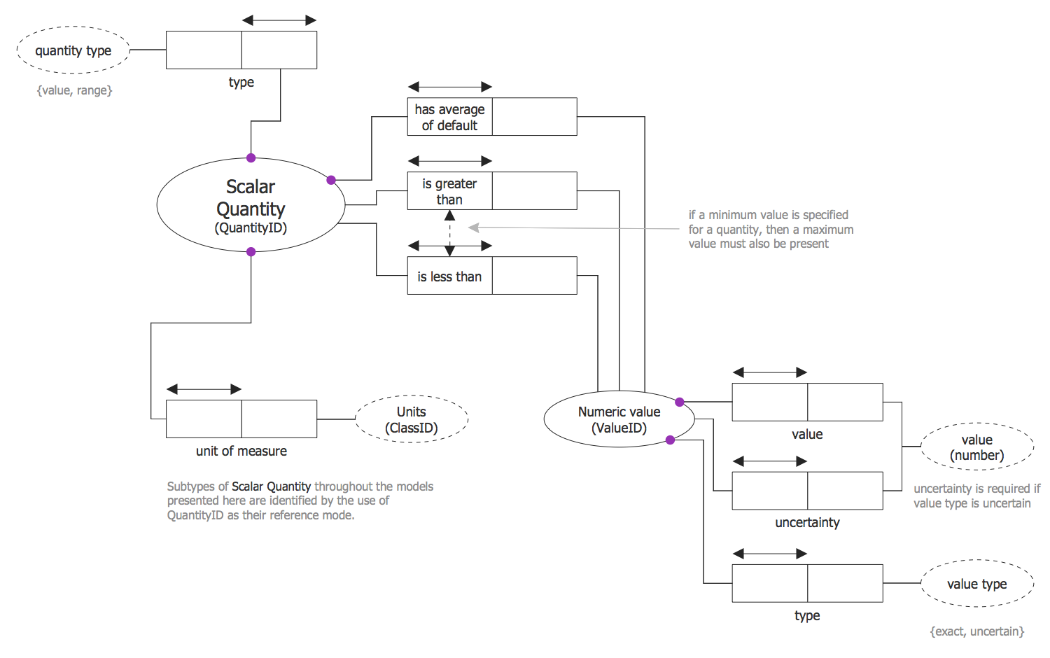
Quantity is one of the main mathematical terms, occurred yet in ancient times. It is an abstract concept, which expresses the category of volume. The most often quantities are applied to represent the measurements that serve for extremely different purposes and to describe the special properties of real objects or phenomena of surrounding world. There are several types of quantities, they can be scalar, each value of which is expressed by one real numeric value (length, area, time, temperature, mass, volume, etc.), or vector that are characterized by value and direction (speed, force, acceleration, electric field, etc.). This sample models and represents the scalar quantity concept. The represented scalar quantities are used to define the numerical values for the whole model. The concept is modeled with several representations, as complex, as quite simple, but in each case the scalar quantity is defined with a specified unit of measurement attribute.
Inside
What I Need to Get Started
Both ConceptDraw DIAGRAM diagramming and drawing software and the Object-role Modeling (ORM) Diagrams solution can help creating the software engineering diagrams you need. The Object-role Modeling (ORM) Diagrams solution can be found in the Software Development area of ConceptDraw STORE application that can be downloaded from this site. Make sure that both ConceptDraw DIAGRAM and ConceptDraw STORE applications are installed on your computer before you get started.
How to install
After ConceptDraw STORE and ConceptDraw DIAGRAM are downloaded and installed, you can install the Object-Role Modeling (ORM) Diagrams solution from the ConceptDraw STORE.
Start Using
To make sure that you are doing it all right, use the pre-designed symbols from the stencil libraries from the solution to make your drawings look smart and professional. Also, the pre-made examples from this solution can be used as drafts so your own drawings can be based on them. Using the samples, you can always change their structures, colors and data.
Object-Role Modeling (ORM) Diagram
ORM is an abbreviation for a powerful method for querying and designing different database models (including creating the database design) at the conceptual level — Object Role Modeling. The application of such models should be described the way for it to become easily understandable by non-technical users. Object Role Modeling data models are known for capturing more business rules as well as being easier to both evolving and validating than data models that use other approaches.
There is a particular conceptual schema used within the Object Role Modeling while it can be used in software engineering for developing the applications and data modeling for modeling the given information. Any object-role model can use different graphical symbols that are known to be based on the first order predicate logic and set theory in order to enable the modeler to make an unambiguous definition of the so-called “arbitrary universe of discourse”.
The term “universe of discourse” is known to be usually referring to some collection of the objects that are being discussed in some specific discourse. Same “universe of discourse” term, but in the model-theoretical semantics, is simply a set of entities that such model is known to be based on.

Pic. 1. Object-Role Modeling (ORM) diagram
Object-Role Modeling can be also known as the “fact-oriented modeling”, treating all facts as relationships (ternary, unary, binary, etc.). It is a conceptual approach to querying and modeling the information semantics of different business domains in order to underlie the facts of interest. Such facts and rules can be always verbalized in language that is simple to be understood by non-technical users of the different business domains.
The mentioned facts are being grouped into structures (such as the attribute-based entity types, relation schemes, classes and/or XML schemas), which is known to be considered a design level. An implementation issue is simply irrelevant to the capturing of different essential business semantics in this case.
Object-Role Modeling is one of the popular conceptual approaches to both modeling and querying the information semantics of business domains, being a synonym to the fact-oriented modeling and avoiding some particular attributes in the base model that enhances the semantic stability, natural verbalization and populatability, and thus facilitating communication with all the stakeholders.
Fact-oriented graphical notations are known to be far more expressive than other ones — those that are provided by other notations. Fact-oriented textual languages are known to be based on the formal subsets of native languages. That is why they are known to be easier to understand by many business people to compare to understanding the technical languages such as the UML’s Object Constraint one (OCL).
Fact-oriented modeling includes different procedures used for mapping to the so-called “attribute based structures”. They are known for being used to the front-end other approaches and the fact-oriented modeling one comprises a family of the “dialects” that are familiar with being closely related ones.
The first version of the conceptual schema design procedure (CSDP) was formulated by G.M. Nijssen who made the fundamental contributions by introducing the so-called "circle-box" notation. Nowadays, there are two notations of ORM. The main goals for the ORM 2 graphical notation are the following: more compact display of ORM models with a good clarity; improved internationalization (such as an avoidance of the English language symbols); notation changes are known to be acceptable to a short-list of key Object Role Modeling users; simplified drawing rules that are known to be used for facilitating a creation of the graphical editors; full support of textual annotations (such as footnoting of the main textual rules); extended usage of views for selectively suppressing/displaying detail and support for new features (for example, role path delineation, modalities and closure aspects.)
In the old ORM graphical notation, the so-called “object type shapes” (value type and entity type) are known to be depicted by the particularly named ellipses. Such ellipses are faster for all those users who prefer drawing manually. Although, they consume more space than rectangles (either soft or hard), especially when the names are long. To compare: for the ORM 2 notation, the default shapes for object types are soft rectangles meaning they are the rectangles with the rounded corners.
Apart from providing a more compact container for any needed enclosed text, all the users can spread the needed text over multiple lines. At the same time, any needed text can be displayed in a user-definable default style and all the individual text elements may be user-selected for alternate styles. The text may be either left, center or right justified. Another well-known feature of the Object Role Modeling is that the ORM and ORM related modeling languages can be distinguished by being attribute-free.

Pic. 2. Object-Role Modeling (ORM) diagram
The full list of the usage of ORM diagrams can illustrate how many fields of business activity can be involved in the process of making the Object-Role Modeling drawings:
information system design (semantic modeling that involves modeling the semantics of a universe of discourse, data modeling and requirements engineering) and software engineering (database modeling that includes modeling both graph databases and relational databases, business rules modeling, XML-Schemas modeling, data warehouses modeling and web forms modeling).
ORM diagram can be created with help of the ConceptDraw DIAGRAM diagramming and drawing software by using the Object-Role Modeling (ORM) diagrams solution. Depicting the objects (entity types), the relationships (fact types) between them and the roles that these objects play in those relationships is much simpler by using the pre-made examples and templates from the previously mentioned solution of ConceptDraw STORE.
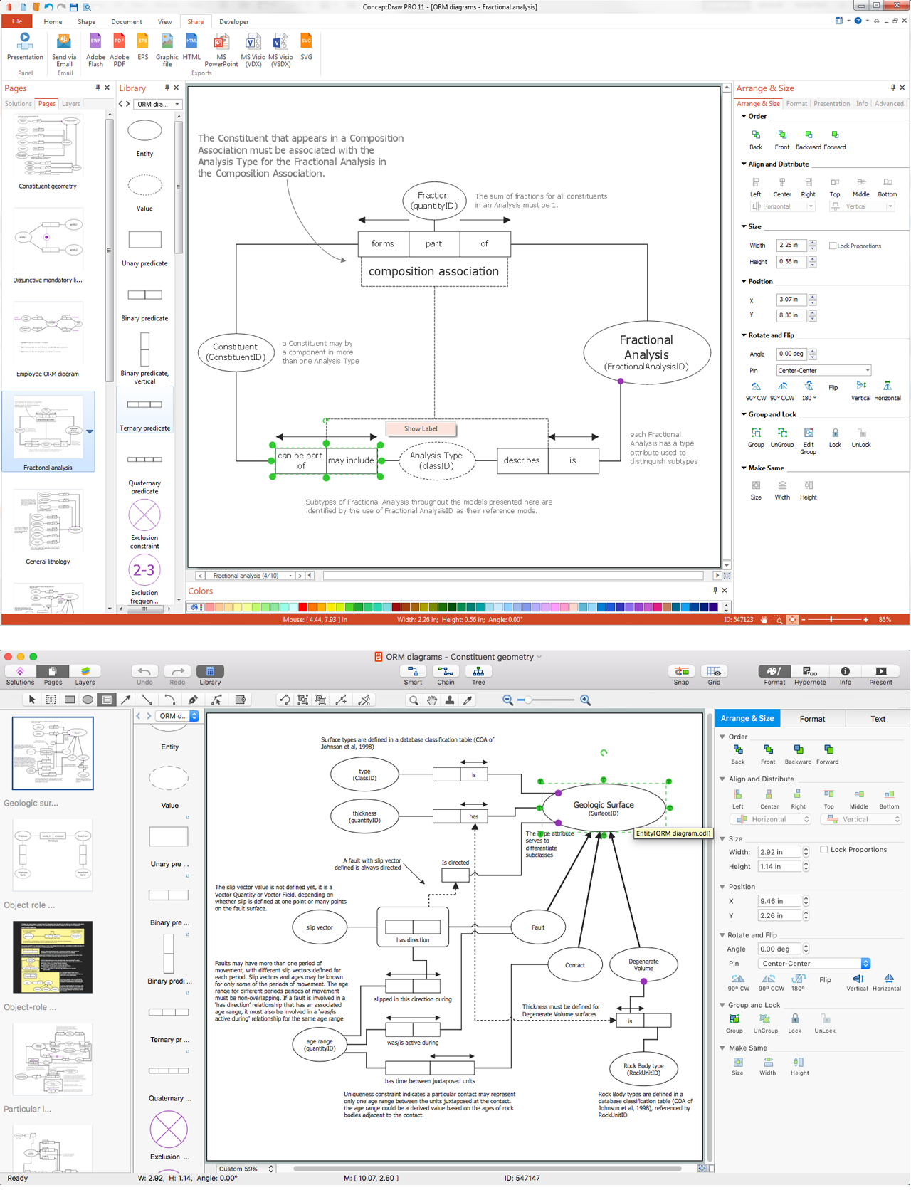
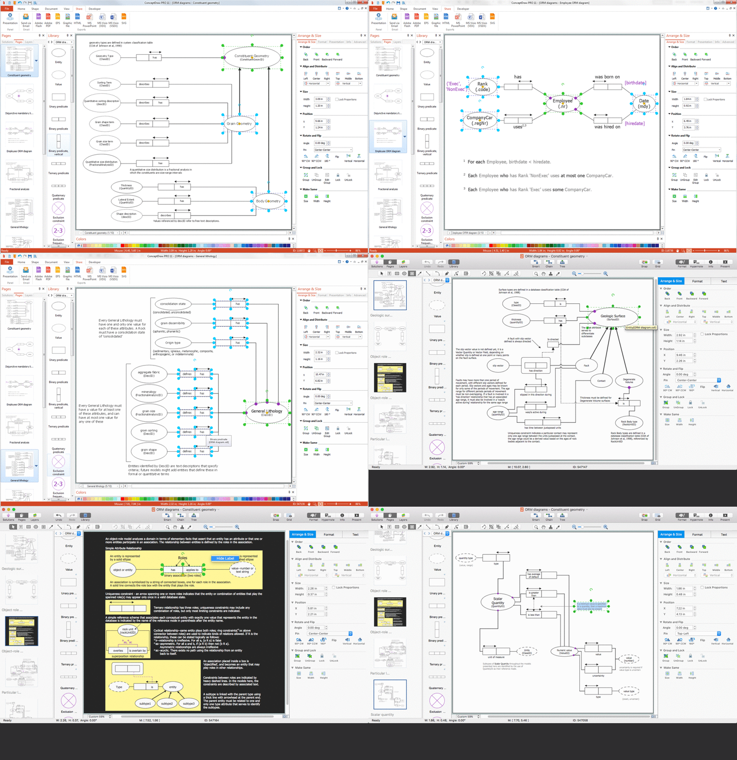
Pic. 3. Object-Role Modeling (ORM) diagrams solution
Both vector stencils libraries and ORM diagrams samples and templates, as well as learning media, are available for all the ConceptDraw DIAGRAM users. Having both ConceptDraw DIAGRAM and ConceptDraw STORE downloaded to your desktop, it is possible to create any needed ORM drawing within a short period of time by using the Object-Role Modeling (ORM) Diagrams solution.