Bubble diagrams in Landscape Design with ConceptDraw DIAGRAM
Bubble Diagrams are the charts with a bubble presentation of data with obligatory consideration of bubble's sizes. They are analogs of Mind Maps and find their application at many fields, and even in landscape design. At this case the bubbles are applied to illustrate the arrangement of different areas of future landscape design, such as lawns, flowerbeds, playgrounds, pools, recreation areas, etc. Bubble Diagram helps to see instantly the whole project, it is easy for design and quite informative, in most cases it reflects all needed information. Often Bubble Diagram is used as a draft for the future landscape project, on the first stage of its design, and in case of approval of chosen design concept is created advanced detailed landscape plan with specification of plants and used materials. Creation of Bubble Diagrams for landscape in ConceptDraw DIAGRAM software is an easy task thanks to the Bubble Diagrams solution from "Diagrams" area. You can use the ready scanned location plan as the base or create it easy using the special ConceptDraw libraries and templates.
 Gym and Spa Area Plans
Gym and Spa Area Plans solution extends abilities of the architects, designers, engineers, builders, marketing experts, gym instructors, fitness trainers, health and beauty services specialists. It is a real finding for all them due to the unique functionally thought-out drawing tools, samples and examples, template and libraries of pre-made vector design elements offered to help create the Gym and Spa area plans, Fitness plans, Gym workout plan, Gym layout plan, Spa design plans, Gym floor plan and Spa floor plan with any degree of detailing.
 Network Layout Floor Plans
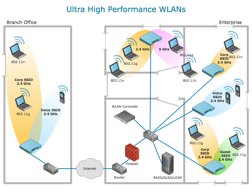
Network Layout Floor Plans solution extends ConceptDraw DIAGRAM software functionality with powerful tools for quick and efficient documentation the network equipment and displaying its location on the professionally designed Network Layout Floor Plans. Never before creation of Network Layout Floor Plans, Network Communication Plans, Network Topologies Plans and Network Topology Maps was not so easy, convenient and fast as with predesigned templates, samples, examples and comprehensive set of vector design elements included to the Network Layout Floor Plans solution. All listed types of plans will be a good support for the future correct cabling and installation of network equipment.
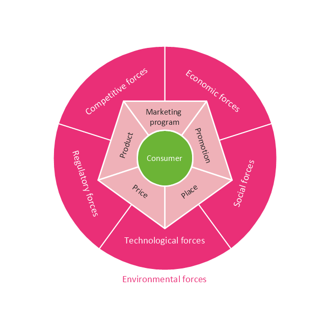
This circular diagram sample was created on the base of the figure from the Florence-Darlington Technical College website. [bus.fdtc.edu/ sbed/ core/ core7.html]
"A marketing plan may be part of an overall business plan. Solid marketing strategy is the foundation of a well-written marketing plan. While a marketing plan contains a list of actions, a marketing plan without a sound strategic foundation is of little use. ...
A marketing plan for a small business typically includes Small Business Administration Description of competitors, including the level of demand for the product or service and the strengths and weaknesses of competitors:
(1) Description of the product or service, including special features.
(2) Marketing budget, including the advertising and promotional plan.
(3) Description of the business location, including advantages and disadvantages for marketing.
(4) Pricing strategy.
(5) Market Segmentation." [Marketing plan. Wikipedia]
The circular diagram example "Marketing plan" was created using the ConceptDraw PRO diagramming and vector drawing software extended with the Target and Circular Diagrams solution from the Marketing area of ConceptDraw Solution Park.
www.conceptdraw.com/ solution-park/ marketing-target-and-circular-diagrams
Using Remote Networking Diagrams
Remote Networking - We explain the method most people use to connect to the Internet.
 Directional Maps
Directional Maps solution extends ConceptDraw DIAGRAM software with templates, samples and libraries of vector stencils for drawing the directional, location, site, transit, road and route maps, plans and schemes.
 Electric and Telecom Plans
The Electric and Telecom Plans solution providing the electric and telecom-related stencils, floor plan electrical symbols and pre-made examples is useful for electricians, interior designers, telecommunications managers, builders and other technicians when creating the electric visual plans and telecom drawings, home electrical plan, residential electric plan, telecom wireless plan, electrical floor plans whether as a part of the building plans or the independent ones.
 Plant Layout Plans
Plant Layout Plans solution can be used for power plant design and plant layout design, for making the needed building plant plans and plant layouts looking professionally good. Having the newest plant layout software, the plant design solutions and in particular the ConceptDraw’s Plant Layout Plans solution, including the pre-made templates, examples of the plant layout plans, and the stencil libraries with the design elements, the architects, electricians, interior designers, builders, telecommunications managers, plant design engineers, and other technicians can use them to create the professionally looking drawings within only a few minutes.
HelpDesk
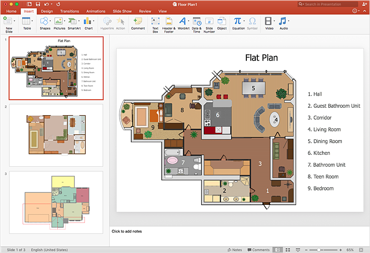
How To Make a PowerPoint Presentation of a Floor Plan
You can use ConceptDraw DIAGRAM to perform amazing PowerPoint presentation of the floor plan that includes the sizes, corners, squares, and other important technical and design details.HelpDesk
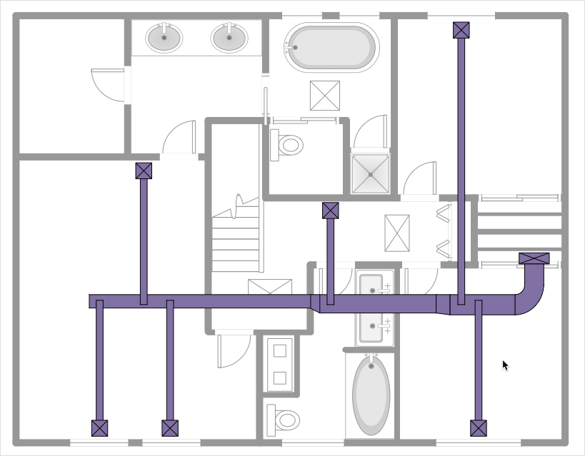
How to Create a HVAC Plan
HVAC plans are used to make and maintain systems of heating and air conditioning. HVAC plan is an important part of building planning. It is developed for private family houses as well as for apartment and public buildings. Making HVAC plans as a part of construction documentation package essential requirement for any building project. Making a plan that shows the location and connection of HVAC equipment involves many different elements that can be managed using ConceptDraw DIAGRAM reinforced with HVAC Plans solution. With ConceptDraw DIAGRAM you can easily create and communicate HVAC plans of any complexity.
 Cafe and Restaurant Floor Plans
Restaurants and cafes are popular places for recreation, relaxation, and are the scene for many impressions and memories, so their construction and design requires special attention. Restaurants must to be projected and constructed to be comfortable and e
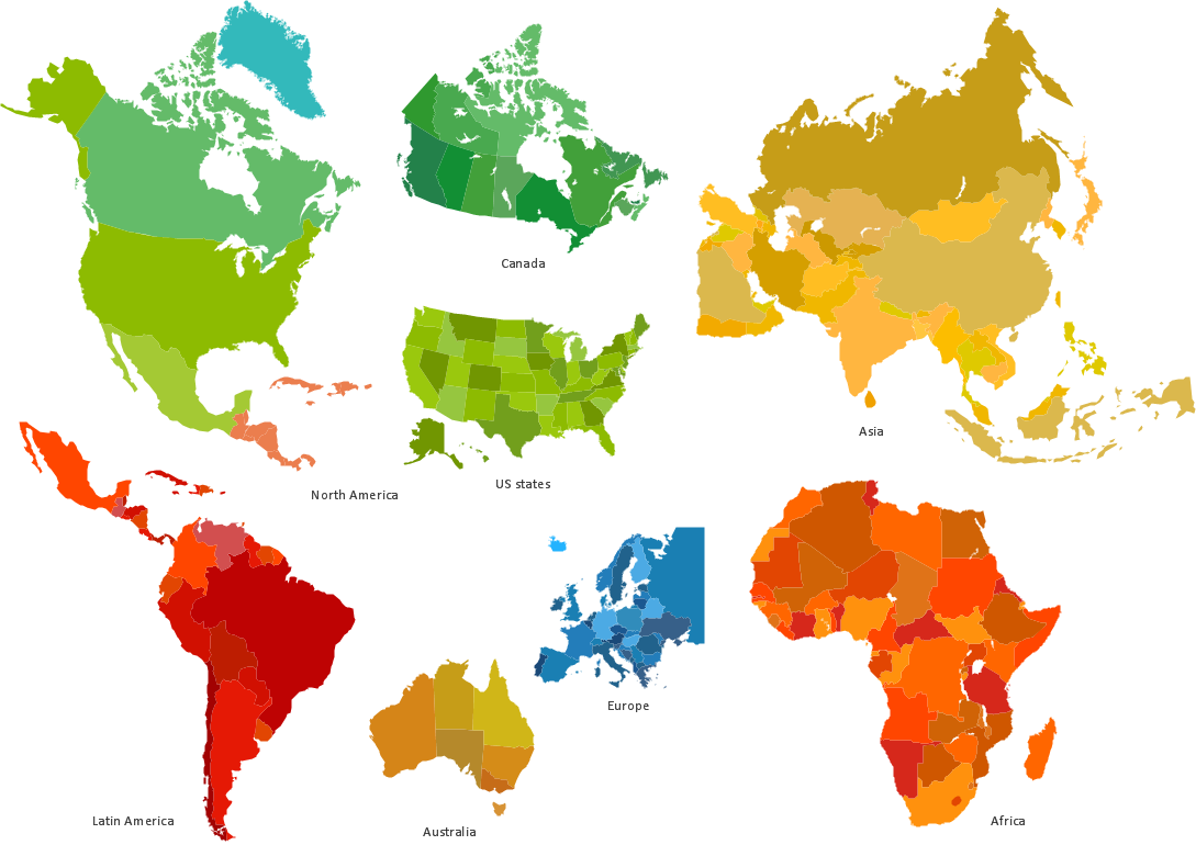
Spatial infographics Design Elements: Location Map
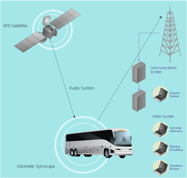
Infographic Design Elements for visually present various geographically distributed information.This vehicular network diagram example was drawn on the base of picture illustrating the article "Automatic Vehicle Location: Rural Transit" from the website of the Research and Innovative Technology Administration (RITA), U.S. Department of Transportation (US DOT).
"Automatic Vehicle Location (AVL) systems calculate the real-time location of any vehicle equipped with a Global Positioning Satellite (GPS) receiver. Data are then transmitted to the transit center with use of radio or cellular communications and can be used immediately for daily operations as well as archived for further analysis.
As a stand-alone technology, an AVL system can be used to monitor on-time performance. When combined with other technologies, AVL can deliver many benefits in the areas of fleet management, service planning, safety and security, traveler information, fare payment, vehicle component monitoring, and data collection. Since the greatest benefits from AVL are achieved by combining it with other Intelligent Transportation System (ITS) technologies, AVL is most appropriate for large rural agencies with more than 30 vehicles that plan to implement a comprehensive ITS."
[pcb.its.dot.gov/ factsheets/ avl/ avlRural_ overview.asp]
The vehicular network diagram example "Automatic vehicle location" was created using the ConceptDraw PRO diagramming and vector drawing software extended with the Vehicular Networking solution from the Computer and Networks area of ConceptDraw Solution Park.
Used Solutions
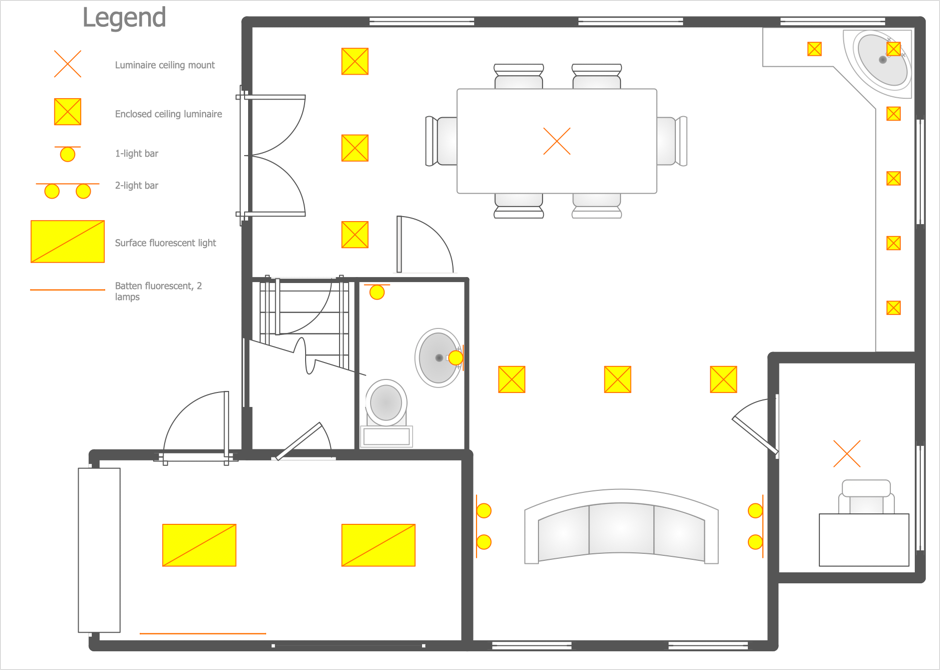
This cafe electrical floor plan sample shows the outlet and switch layout.
"An electrical drawing, is a type of technical drawing that shows information about power, lighting, and communication for an engineering or architectural project. Any electrical working drawing consists of "lines, symbols, dimensions, and notations to accurately convey an engineering's design to the workers, who install the electrical system on the job".
A complete set of working drawings for the average electrical system in large projects usually consists of:
(1) A plot plan showing the building's location and outside electrical wiring.
(2) Floor plans showing the location of electrical systems on every floor.
(3) Power-riser diagrams showing panel boards.
(4) Control wiring diagrams.
(5) Schedules and other information in combination with construction drawings.
Electrical drafters prepare wiring and layout diagrams used by workers who erect, install, and repair electrical equipment and wiring in communication centers, power plants, electrical distribution systems, and buildings." [Electrical drawing. Wikipedia]
The outlet and switch layout example "Cafe electrical floor plan" was created using the ConceptDraw PRO diagramming and vector drawing software extended with the Electric and Telecom Plans solution from the Building Plans area of ConceptDraw Solution Park.
HelpDesk
How to Create a Reflected Ceiling Plan
A Reflected Ceiling Plan (RCP) is a drawing of a room or building, looking down at the interior ceiling. Making RCP involves many different reflected ceiling plan symbols that can be managed using ConceptDraw DIAGRAM. You can design the reflected ceiling floor plan that shows the location of light fixtures and any other items that may be suspended from the ceiling. You can share your ceiling design ideas by saving drawings as graphics files or printing them.- Bubble diagrams in Landscape Design with ConceptDraw PRO ...
- Seven Management and Planning Tools | Bubble diagrams in ...
- How To Create Restaurant Floor Plans in Minutes | Bubble diagrams ...
- Location Plan
- Create Floor Plans easily with ConceptDraw PRO! | Bubble ...
- Engineering | Technical Drawing Software | Universal Diagramming ...
- Flowchart on Bank. Flowchart Examples | Bubble diagrams in ...
- How To Create Emergency Plans | How To use Electrical and ...
- Wiring Diagrams with ConceptDraw PRO | Restaurant Floor Plans ...
- Electrical Drawing Software | How To use House Electrical Plan ...
- Seven Management and Planning Tools | Example of Flowchart ...
- Bubble Diagrams | ConceptDraw Solution Park | How to Add a ...
- Bubble diagram template | Basic Diagramming | Best Diagramming ...
- How To Create a Bubble Chart | Bubble diagrams with ...
- How To Create a Bubble Chart | Bubble diagrams in Landscape ...
- Bubble Diagrams | Bubble diagrams with ConceptDraw PRO ...
- How To Do A Mind Map In PowerPoint | Floor Plans | Business ...
- Bubble diagrams with ConceptDraw PRO | Bubble diagrams in ...
- Entity-Relationship Diagram (ERD) | Event-driven Process Chain ...
- Wiring Diagrams with ConceptDraw PRO | How To Draw Building ...

