- Electric and Telecom Plans Free
- Fire and Emergency Plans Free
- Floor Plans Free
- Plant Layout Plans Free
- School and Training Plans Free
- Seating Plans Free
- Security and Access Plans Free
- Site Plans Free
- Sport Field Plans Free
- Business Process Diagrams Free
- Business Process Mapping Free
- Classic Business Process Modeling Free
- Cross-Functional Flowcharts Free
- Event-driven Process Chain Diagrams Free
- IDEF Business Process Diagrams Free
- Logistics Flow Charts Free
- Workflow Diagrams Free
- ConceptDraw Dashboard for Facebook Free
- Mind Map Exchange Free
- MindTweet Free
- Note Exchange Free
- Project Exchange Free
- Social Media Response Free
- Active Directory Diagrams Free
- AWS Architecture Diagrams Free
- Azure Architecture Free
- Cisco Network Diagrams Free
- Cisco Networking Free
- Cloud Computing Diagrams Free
- Computer Network Diagrams Free
- Google Cloud Platform Free
- Interactive Voice Response Diagrams Free
- Network Layout Floor Plans Free
- Network Security Diagrams Free
- Rack Diagrams Free
- Telecommunication Network Diagrams Free
- Vehicular Networking Free
- Wireless Networks Free
- Comparison Dashboard Free
- Composition Dashboard Free
- Correlation Dashboard Free
- Frequency Distribution Dashboard Free
- Meter Dashboard Free
- Spatial Dashboard Free
- Status Dashboard Free
- Time Series Dashboard Free
- Basic Circle-Spoke Diagrams Free
- Basic Circular Arrows Diagrams Free
- Basic Venn Diagrams Free
- Block Diagrams Free
- Concept Maps Free
- Family Tree Free
- Flowcharts Free
- Basic Area Charts Free
- Basic Bar Graphs Free
- Basic Divided Bar Diagrams Free
- Basic Histograms Free
- Basic Line Graphs Free
- Basic Picture Graphs Free
- Basic Pie Charts Free
- Basic Scatter Diagrams Free
- Aerospace and Transport Free
- Artwork Free
- Audio, Video, Media Free
- Business and Finance Free
- Computers and Communications Free
- Holiday Free
- Manufacturing and Maintenance Free
- Nature Free
- People Free
- Presentation Clipart Free
- Safety and Security Free
- Analog Electronics Free
- Audio and Video Connectors Free
- Basic Circuit Diagrams Free
- Chemical and Process Engineering Free
- Digital Electronics Free
- Electrical Engineering Free
- Electron Tube Circuits Free
- Electronic Block Diagrams Free
- Fault Tree Analysis Diagrams Free
- GHS Hazard Pictograms Free
- Home Automation and Wiring Free
- Mechanical Engineering Free
- One-line Diagrams Free
- Power Сircuits Free
- Specification and Description Language (SDL) Free
- Telecom and AV Circuits Free
- Transport Hazard Pictograms Free
- Data-driven Infographics Free
- Pictorial Infographics Free
- Spatial Infographics Free
- Typography Infographics Free
- Calendars Free
- Decision Making Free
- Enterprise Architecture Diagrams Free
- Fishbone Diagrams Free
- Organizational Charts Free
- Plan-Do-Check-Act (PDCA) Free
- Seven Management and Planning Tools Free
- SWOT and TOWS Matrix Diagrams Free
- Timeline Diagrams Free
- Australia Map Free
- Continent Maps Free
- Directional Maps Free
- Germany Map Free
- Metro Map Free
- UK Map Free
- USA Maps Free
- Customer Journey Mapping Free
- Marketing Diagrams Free
- Matrices Free
- Pyramid Diagrams Free
- Sales Dashboard Free
- Sales Flowcharts Free
- Target and Circular Diagrams Free
- Cash Flow Reports Free
- Current Activities Reports Free
- Custom Excel Report Free
- Knowledge Reports Free
- MINDMAP Reports Free
- Overview Reports Free
- PM Agile Free
- PM Dashboards Free
- PM Docs Free
- PM Easy Free
- PM Meetings Free
- PM Planning Free
- PM Presentations Free
- PM Response Free
- Resource Usage Reports Free
- Visual Reports Free
- House of Quality Free
- Quality Mind Map Free
- Total Quality Management TQM Diagrams Free
- Value Stream Mapping Free
- Astronomy Free
- Biology Free
- Chemistry Free
- Language Learning Free
- Mathematics Free
- Physics Free
- Piano Sheet Music Free
- Android User Interface Free
- Class Hierarchy Tree Free
- Data Flow Diagrams (DFD) Free
- DOM Tree Free
- Entity-Relationship Diagram (ERD) Free
- EXPRESS-G data Modeling Diagram Free
- IDEF0 Diagrams Free
- iPhone User Interface Free
- Jackson Structured Programming (JSP) Diagrams Free
- macOS User Interface Free
- Object-Role Modeling (ORM) Diagrams Free
- Rapid UML Free
- SYSML Free
- Website Wireframe Free
- Windows 10 User Interface Free
Electric and Telecom Plans
Telecommunications and electrification are widely used all over the world and have become part of our daily life. Modern technologies are used and developed in both of these areas. Electrification is the process of generating electricity; telecommunications is a method of communication using technology.
Telecommunication is applied to transmit information over a distance using signals. The radio, optical, wire, and other electromagnetic systems are used to transmit signals, signs, messages, writings, words, images, and information of any nature. The use of technologies to exchange information between the communication participants is obligatory for telecommunication. The mentioned information is transmitted either electrically over physical media (e.g., cables) or via electromagnetic radiation.
The so-called “transmission paths” are often divided into “communication channels” and afford the advantages of multiplexing. Their mention is always possible on the telecom plans created in the ConceptDraw DIAGRAM software. Electric power transmission in the scale of transmission networks, from the power plants to electrical substations and then to the buildings, and its distribution between the buildings and within a particular building require a detailed plan. In addition, each room and each premise requires its own electrical design plan. With ConceptDraw DIAGRAM diagramming and drawing software, you can easily work with electrical and telecommunications and quickly create all this variety of plans.
The electrical and telecom plans are often included to the obligatory set of working drawings and designs for building construction. These documents define all the needed specifications of a residential house, including the construction ones. Among them are materials, dimensions, layouts, techniques, installation methods, etc.
The electrical and telecom plans are typically constructed based on the building floor plan. Any floor plan is also known as a building plan and is an overhead view of the completed house. Floor plans are designed to indicate the rooms, all windows, doors, and more built-in elements (e.g., cabinets and plumbing fixtures, furnaces, and water heaters, etc.). All the dimensions are usually marked between the walls in order to specify the wall lengths and room sizes. Floor plans can include the needed notes for specifying the finishes, the symbols for electrical items and/or the construction methods.
Site plans are also required in order to show the location of some building, whether it is home or office. Being an overhead view of the construction site, the site plans should outline the location of the setback requirements, utility services, easements, and the location of walkways, driveways and topographical data, sometimes specifying the slope of the terrain. Both floor plans and site plans are widely created in ConceptDraw DIAGRAM.
The Electric and Telecom Plan solution was developed by the CS Odessa team to provide ConceptDraw DIAGRAM users with stencils related to electricity and telecommunications, electrical floor plan symbols and ready-made examples. The solution tools are useful for creating the electric visual plans and telecom drawings, home electrical plan, residential electric plan, telecom wireless plan, electrical floor plans whether as a part of the building plans or the independent ones.
The Electric and Telecom Plans solution is useful for electricians, architects, interior designers, telecommunications managers, builders, technicians, and more construction-related specialists.
-
Install this solution Free -
What I need to get started -
Solution Requirements - This solution requires the following products to be installed:
ConceptDraw DIAGRAM v18 - This solution requires the following products to be installed:
-
Compatibility - Sonoma (14), Sonoma (15)
MS Windows 10, 11 - Sonoma (14), Sonoma (15)
-
Support for this Solution -
Helpdesk
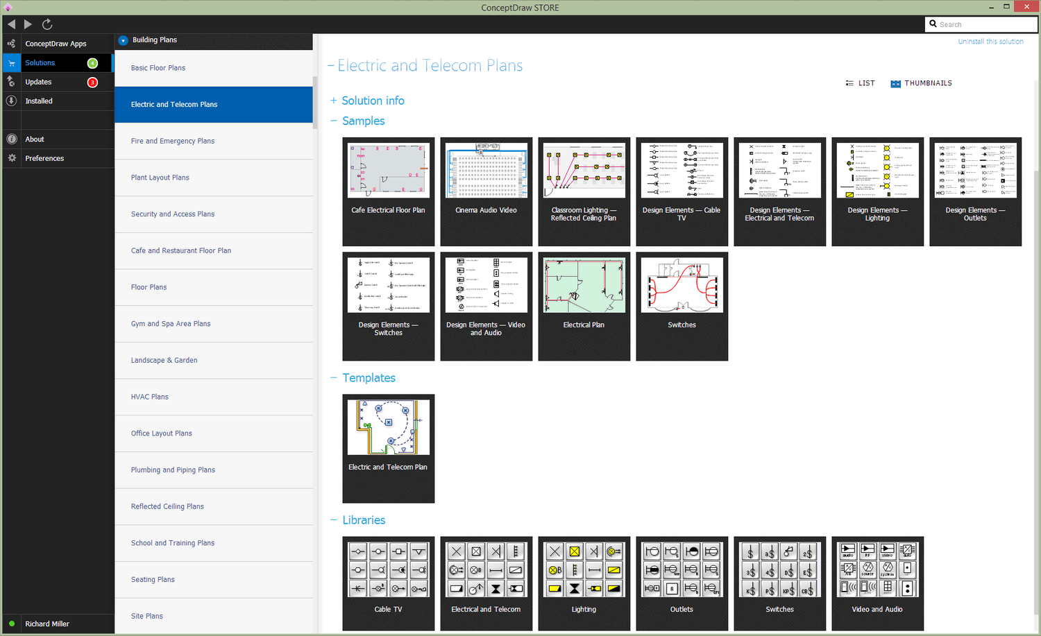
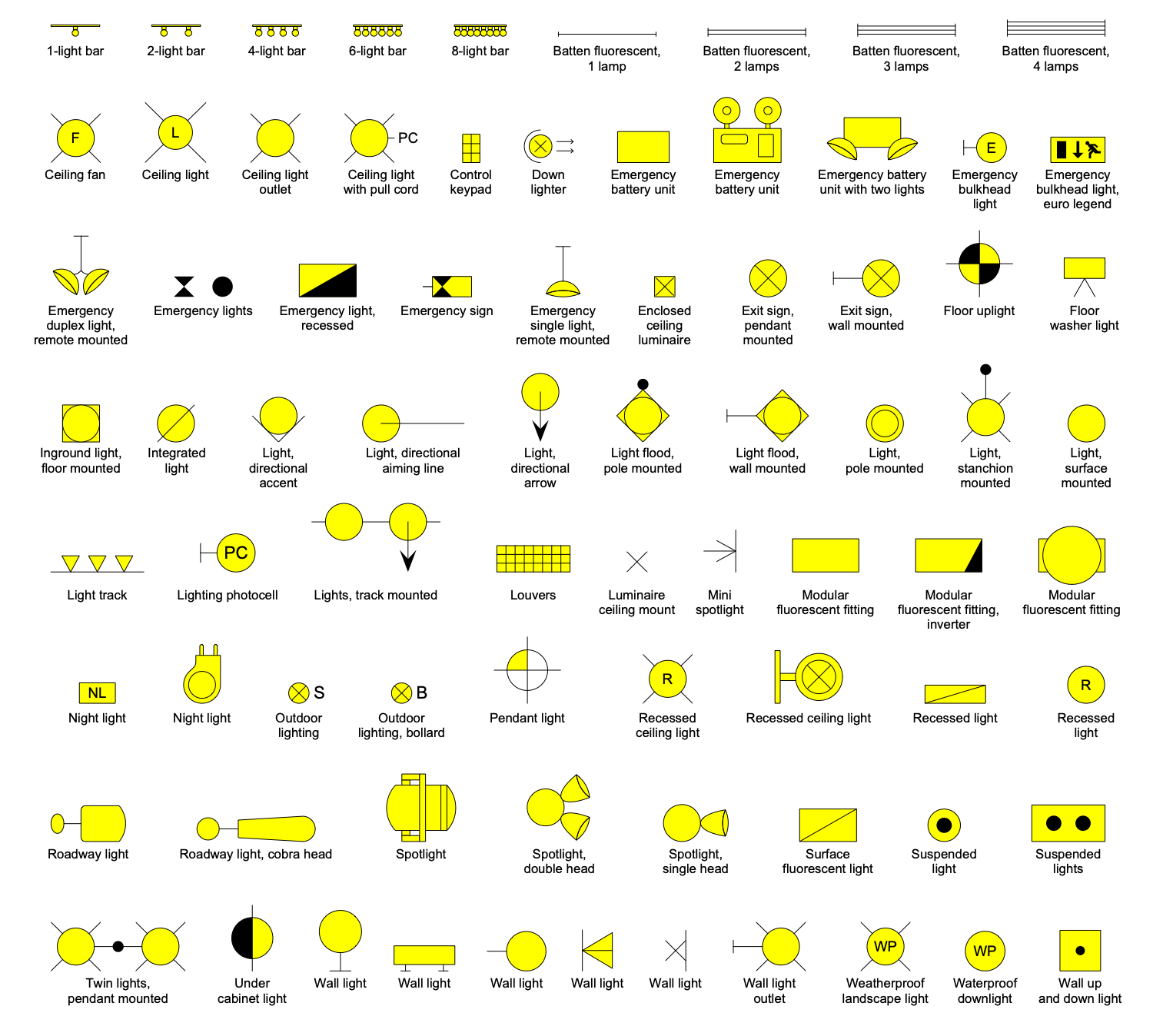
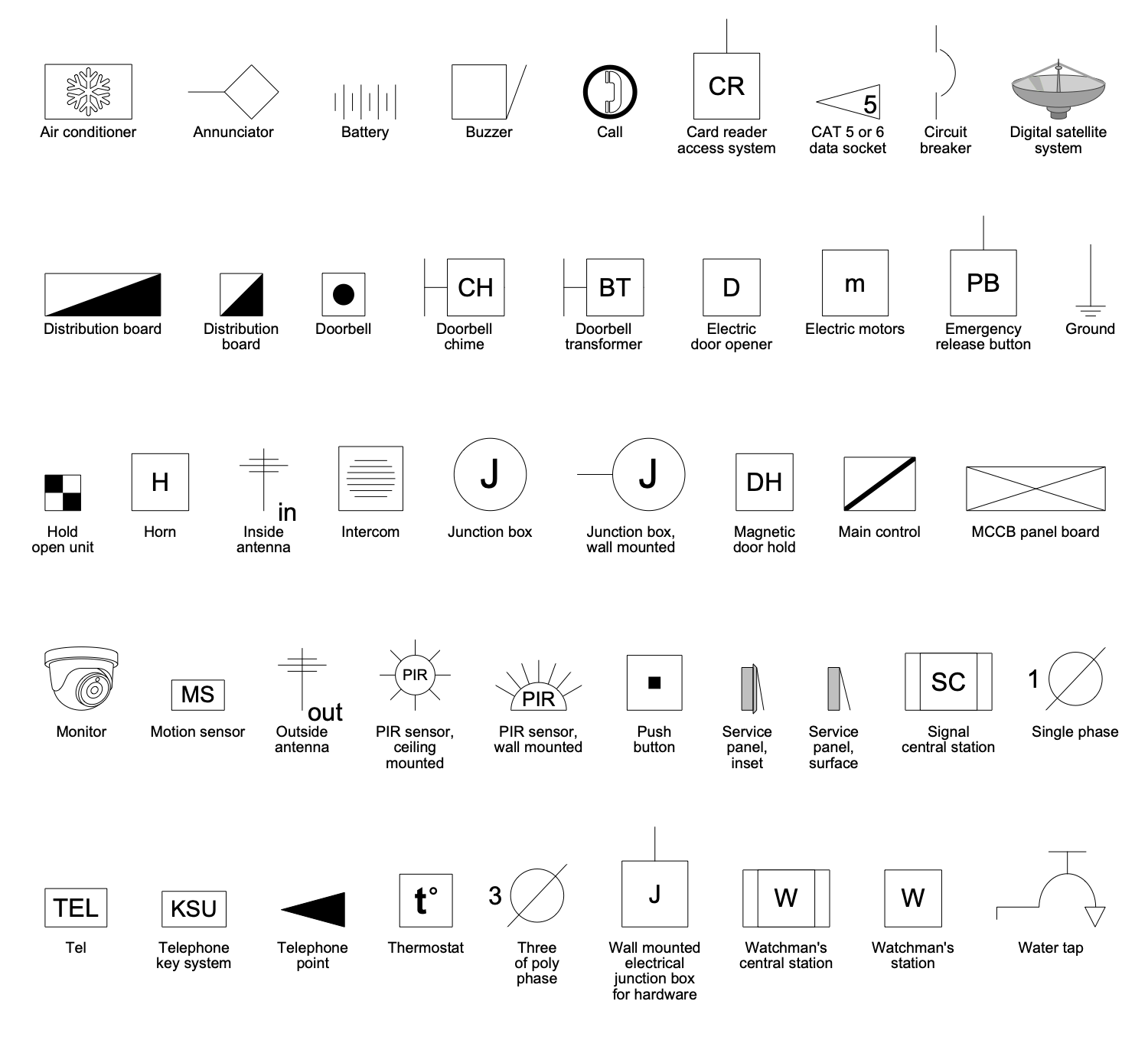
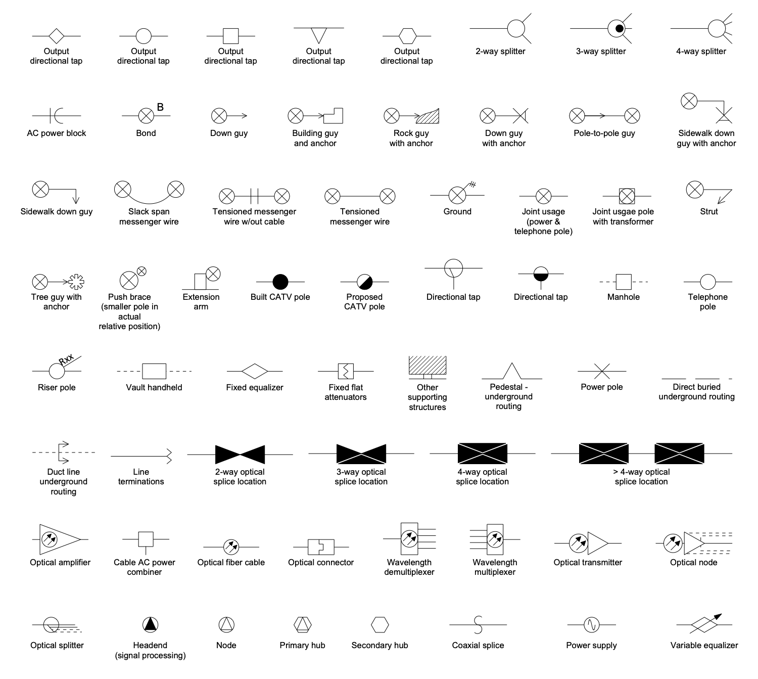
There are 9 stencil libraries containing 403 vector objects and 14 examples in the Electric and Telecom Plans solution.
Design Elements — Lighting
Design Elements — Electrical and Telecom
Design Elements — Cable TV
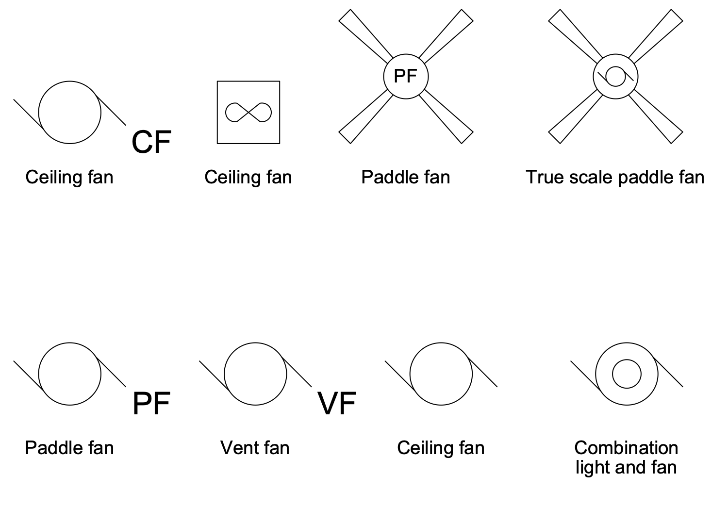
Design Elements Electric and Telecom Plans — Fans
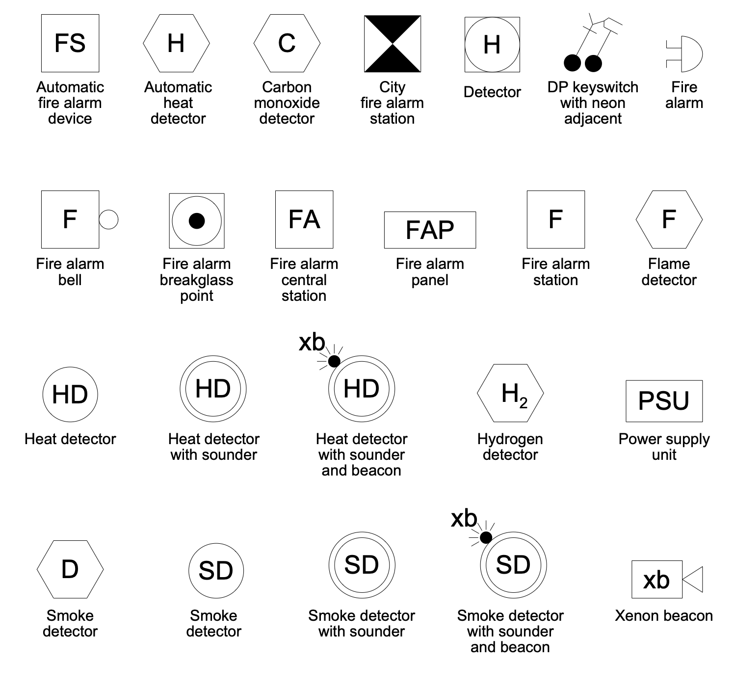
Design Elements Electric and Telecom Plans — Fire Alarm
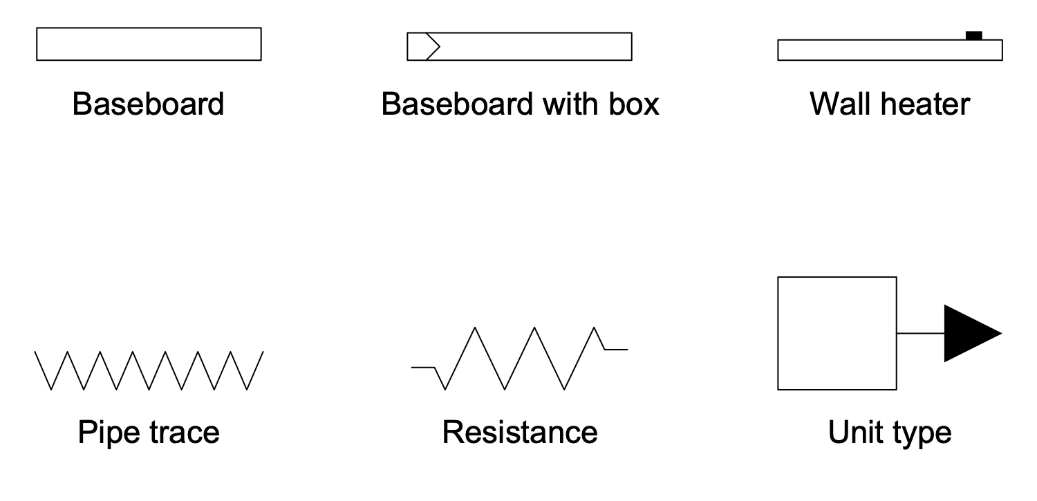
Design Elements Electric and Telecom Plans — Heaters
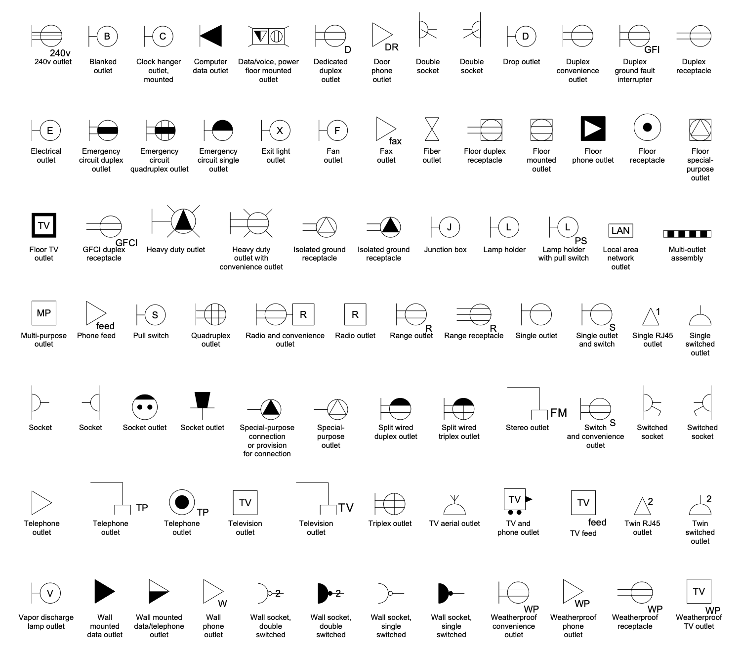
Design Elements Electric and Telecom Plans — Outlets
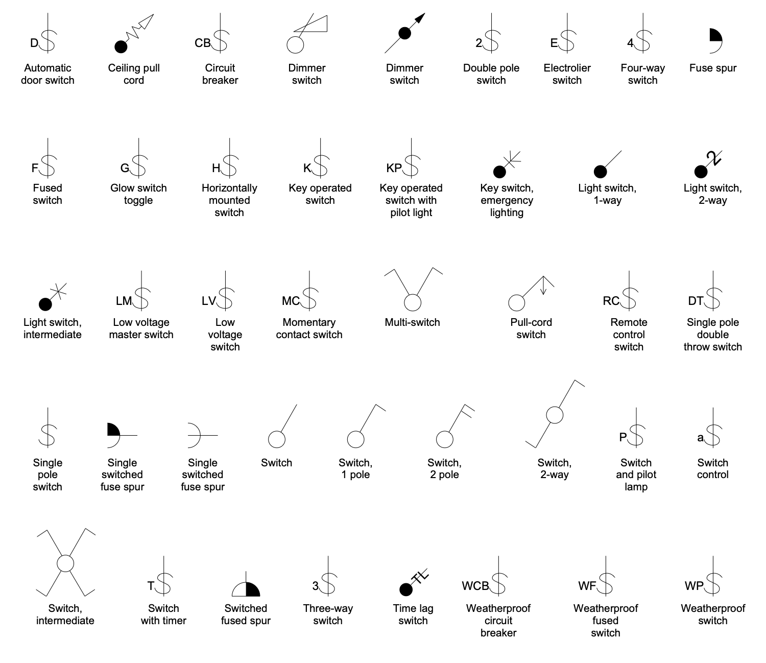
Design Elements Electric and Telecom Plans — Switches and Fuse Spurs
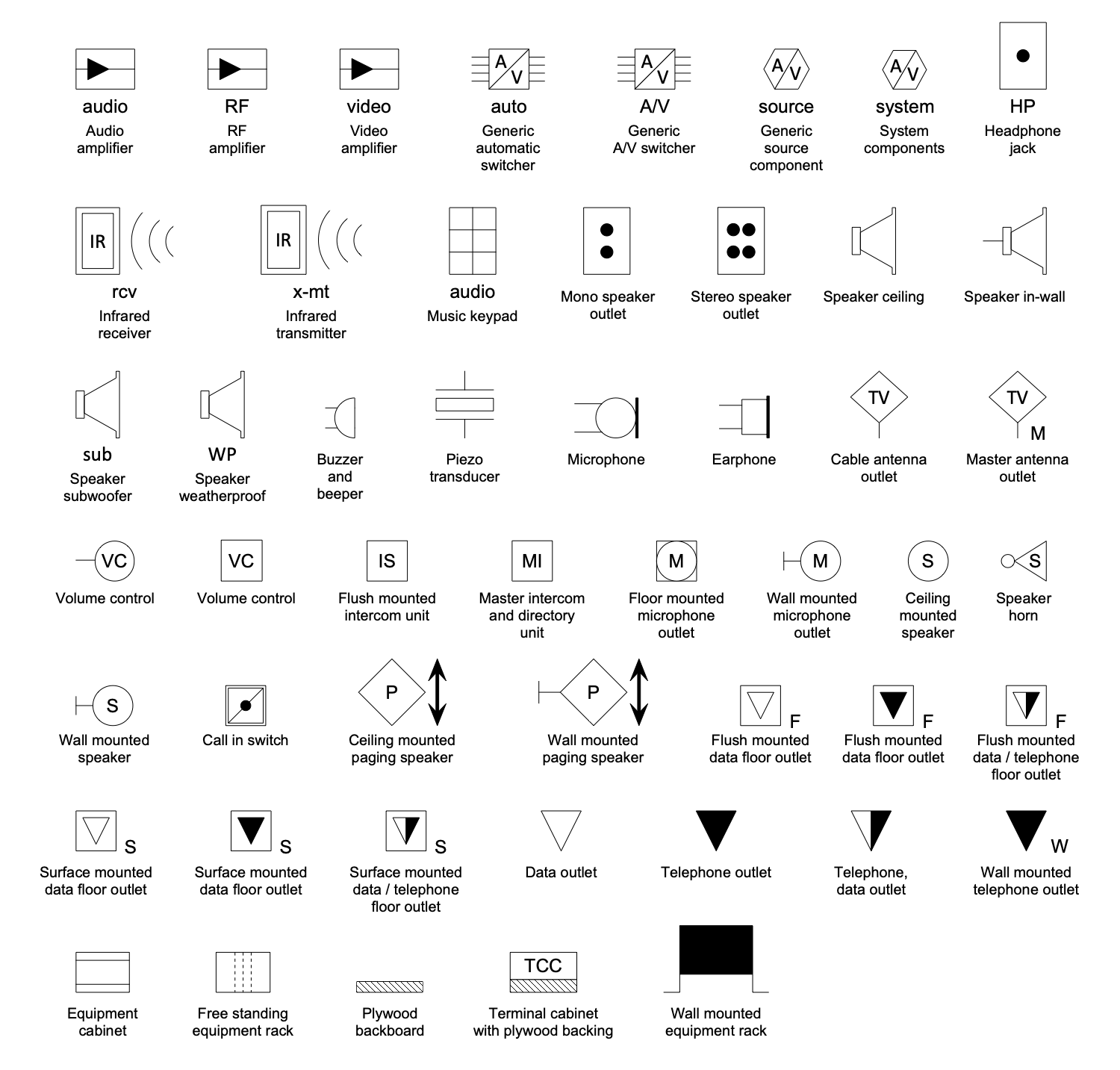
Design Elements Electric and Telecom Plans — Video and Audio
Electric and Telecom Plans Examples
There are a few samples that you see on this page which were created in the ConceptDraw DIAGRAM application by using the Electric and Telecom Plans solution. Some of the solution's capabilities as well as the professional results which you can achieve are all demonstrated here on this page.
All source documents are vector graphic documents which are always available for modifying, reviewing and/or converting to many different formats, such as MS PowerPoint, PDF file, MS Visio, and many other graphic ones from the ConceptDraw Solution Park or ConceptDraw STORE. The Electric and Telecom Plans solution is available to all ConceptDraw DIAGRAM users to get installed and used while working in the ConceptDraw DIAGRAM diagramming and drawing software.
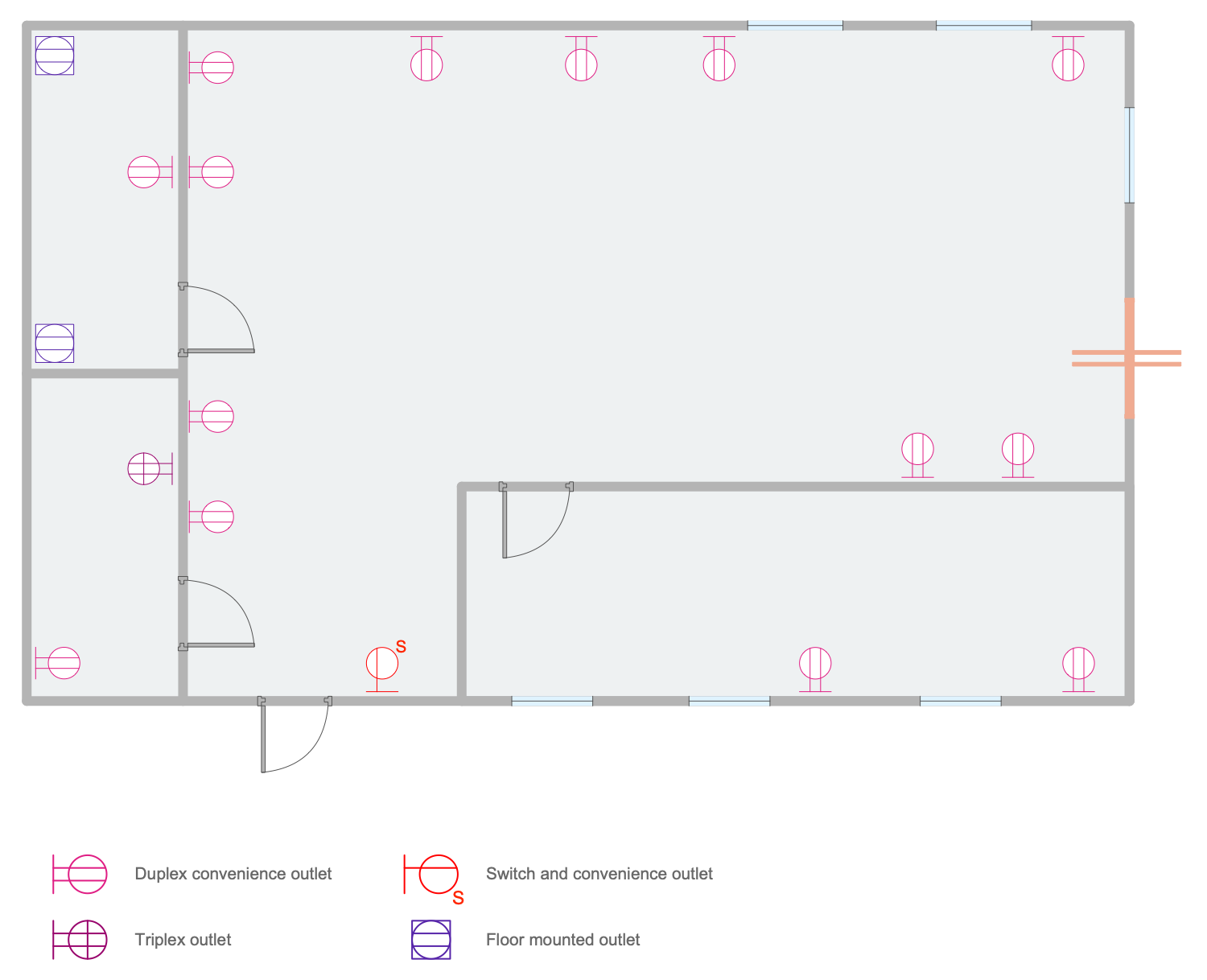
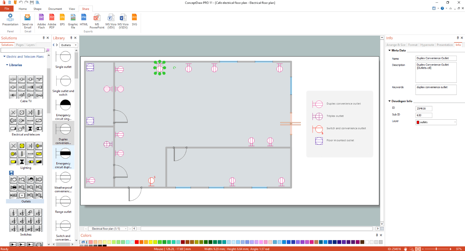
Example 1: Cafe Electrical Floor Plan
This diagram was created in ConceptDraw DIAGRAM using a combination of libraries from the Electric and Telecom Plans Solution. An experienced user spent 10 minutes creating this sample.
This sample shows the detailed electrical plan designed based on the cafe floor plan. Being an obligatory part of the building documentation, an electrical plan is created before the construction of any building or repairing the premises. This technical drawing provides information on the power supply, lighting, and communication in the cafe premises. Creating of electric visual plans is extremely easy process due to the libraries of predesigned vector elements included in Electric and Telecom Plans Solution. Moreover, all these elements are commonly accepted lines, symbols, notations, and dimensions. For this reason, your electrical plans will be easy-readable and correctly executed by all workers installing or repairing the electrical system and electrical equipment. With ConceptDraw DIAGRAM, you can create equally easy the electric visual plan for a single room, apartment, one floor or a whole house, multi-floor building or group of buildings. You can show the location of each of them and depict the inside and outside electrical wiring.
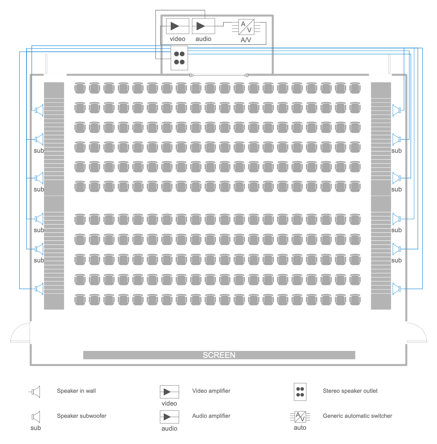
Example 2: Cinema Audio Video
This diagram was created in ConceptDraw DIAGRAM using a combination of libraries from the Electric and Telecom Plans Solution and Sofas and Chairs Library from the Floor Plans Solution. An experienced user spent 20 minutes creating this sample.
The modern cinema is very popular due to the use of the latest digital technologies and newest audio, video and acoustic equipment to playback the high-quality video and sound. This electrical drawing sample shows the audio and video equipment used within the cinema and the scheme of their location on the cinema seating plan. Solutions of the Building Plans area for ConceptDraw DIAGRAM software is a real help for designers, constructors, builders, electricians, and many other people related to construction, electricity, and telecommunication. Installed equipment includes built-in speakers, subwoofers, video amplifiers, audio amplifiers, stereo outputs, and standard auto switches. All of them are presented in the plan by pre-designed vector symbols from the solution libraries and, in addition, have a description in the form of a legend. Located next to the diagram, the legend is always in front of your eyes. This explains the meaning of the symbols and makes your diagram understandable for everyone.
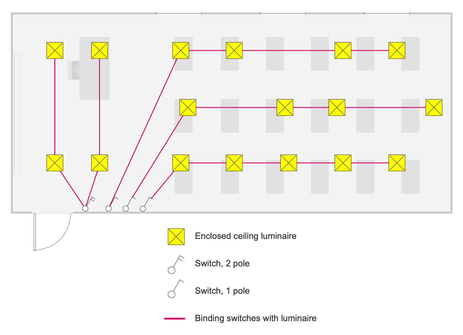
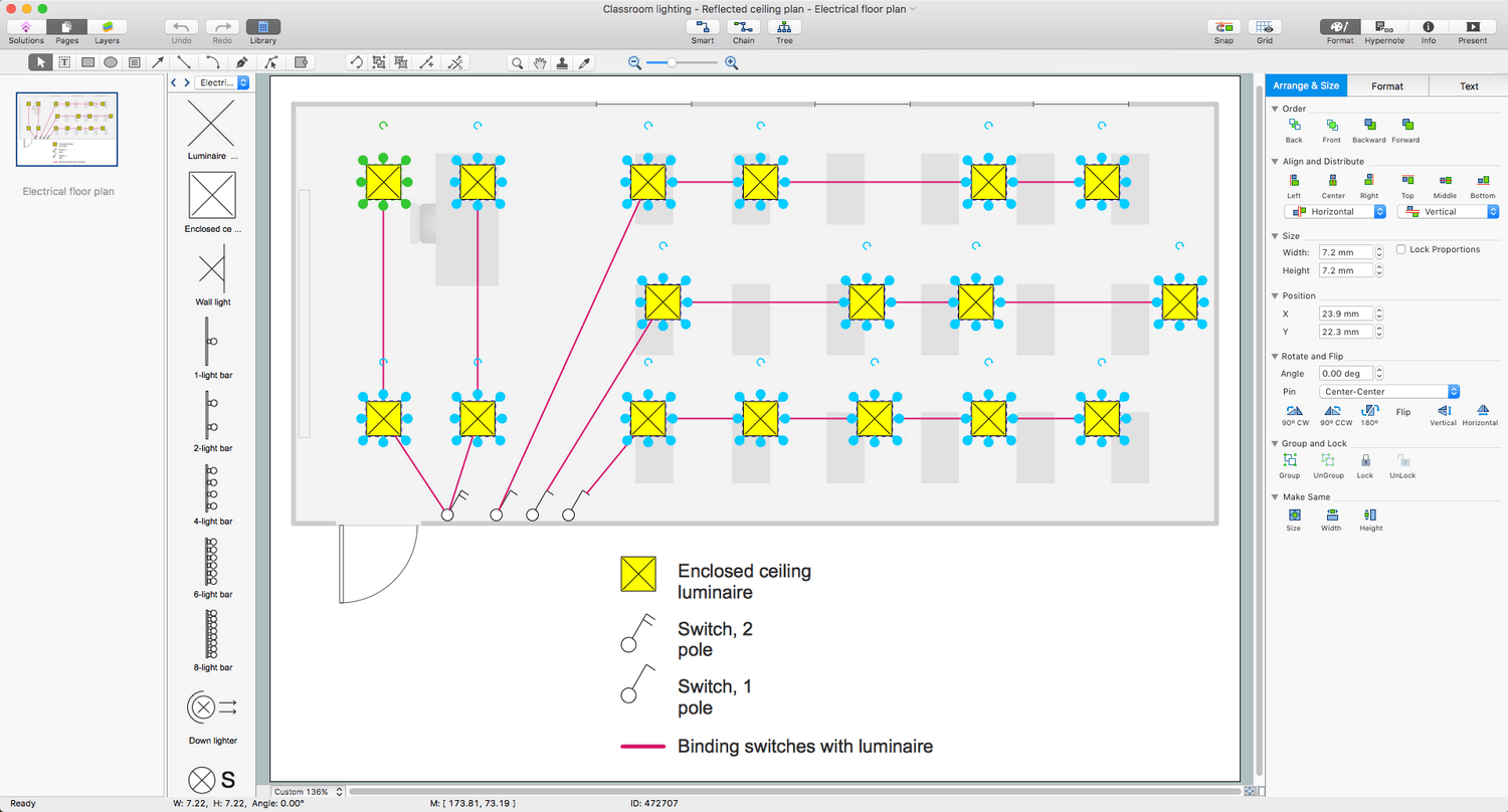
Example 3: Classroom Lighting Reflected Ceiling Plan
This diagram was created in ConceptDraw DIAGRAM using a combination of libraries from the Electric and Telecom Plans Solution. An experienced user spent 10 minutes creating this sample.
High-quality lighting in rooms and other spaces is incredibly important. This is especially true of classrooms in schools, in universities, colleges and other educational institutions and premises in kindergartens. After all, lighting affects both the health of children and the effectiveness of their training. Therefore, architectural lighting technology and design is a special area. Its specialists specialize in the professional lighting of buildings and know the lighting standards, lighting design, the nature of lighting, technologies in this area, the physics, production, and distribution of lamps, etc. This sample shows a reflective ceiling plan for classroom lighting. All lighting objects, including enclosed ceiling luminaires, single and double pole switches, and luminaire switches, were taken from the ConceptDraw Electric and Telecom Plan solution libraries. Their list with semantic descriptions is also shown in the diagram.
Example 4: Electrical Plan
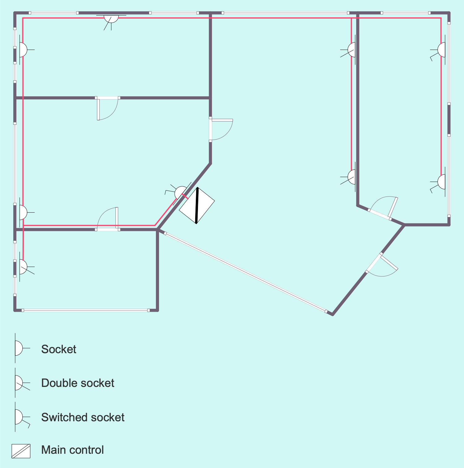
This diagram was created in ConceptDraw DIAGRAM using a combination of libraries from the Electric and Telecom Plans Solution and Floor Plans Solution. An experienced user spent 15 minutes creating this sample.
This sample shows an electrical diagram of an apartment. In fact, it is a plan for the location of outlets, dual outlets, switched outlets, and a plan for the wiring between them. The location of the main control unit is also marked. Feel free to use colors when designing your home power plan, power or wireless network plan in the ConceptDraw DIAGRAM app — colors make your plans more compelling, understandable and successful. The wiring is shown in red and is immediately striking. It's a rigorous electrical plan, it doesn't distract stakeholders from the apartment's design, furniture, and accessories that are commonly found in any apartment. But electrical elements including lamps, lighting fixtures, electrical appliances are easily added to it at any time to make the apartment plan as extensive and detailed as possible. The well-thought-out electrical and telecommunication layout of the apartment allows you to create comfortable living conditions in it.
Example 5: Switches
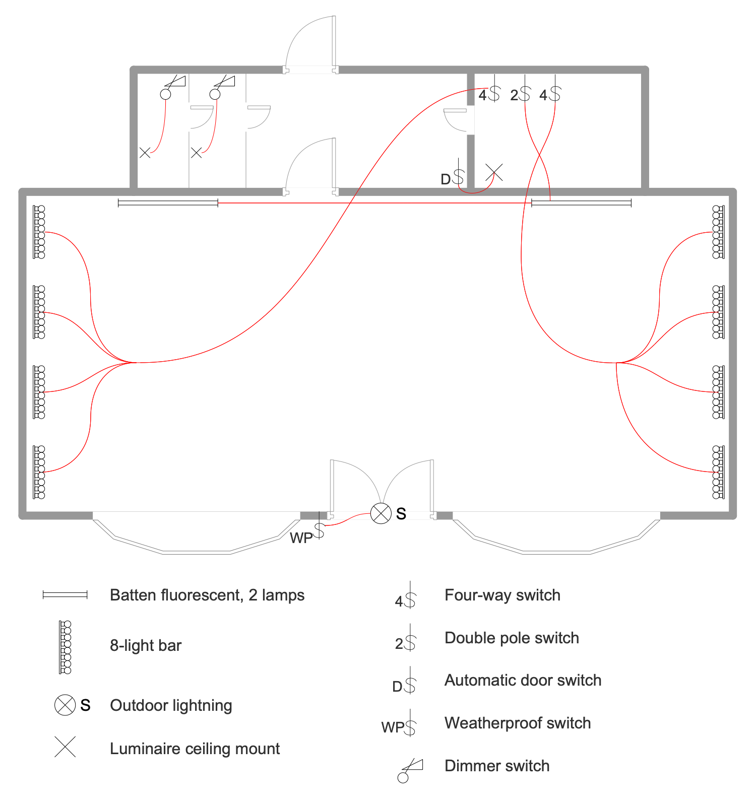
This diagram was created in ConceptDraw DIAGRAM using a combination of libraries from the Electric and Telecom Plans Solution and Floor Plans Solution. An experienced user spent 15 minutes creating this sample.
This wiring diagram example is a prime example of a circuit breaker layout. Light switches are devices that control lighting, electrical outlets, electrical equipment, and electrical appliances. You can easily move the switches on the plan to position them in the ideal way. This will make it possible to avoid mistakes during the further installation of electrical equipment in the building. Various types of switches have been invented and installed. ConceptDraw DIAGRAM's powerful vector graphics software also gives you the versatility and flexibility of choice — a full variety of switches are available in the Switches library from the Electric and Telecom Plans solution. The large hall shown in this diagram is equipped with several 8 light strips located symmetrically on both sides of the room, close to the walls and at the same distance from each other. ConceptDraw DIAGRAM tools make it easy to maintain the same distance between lamps and other lighting fixtures on the plan.
Example 6: Apartment Lighting Plan
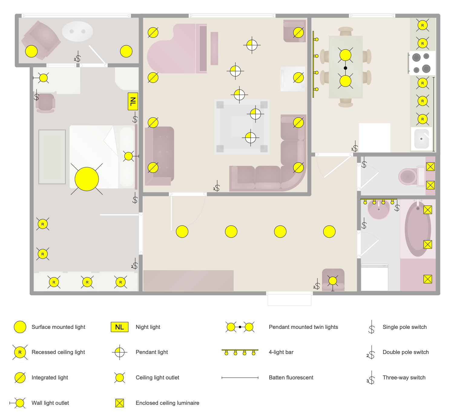
This diagram was created in ConceptDraw DIAGRAM using a combination of libraries from the Electric and Telecom Plans Solution and Floor Plans Solution. An experienced user spent 25 minutes creating this sample.
This sample shows the lighting plan for an apartment. This plan was created from the floor plan with the furniture arrangement and gives a complete picture of its design. You can see how the lighting equipment is in harmony with furniture and appliances. Various points are important, including apartment size, practicality, usability, and aesthetics. Places of increased illumination are immediately visible on the plan. These are areas for work and rest. Usually, this is a desk, dining set, sofa, and armchairs. The lighting of the apartment includes various lighting equipment. It uses surface-mounted luminaires, recessed luminaires, recessed ceiling and indoor ceiling luminaires, ceiling and wall luminaires, night light, pendant single and twin lights, 4-light bar luminaires, and fluorescent battens. Depending on the needs, various types of circuit breakers are used: single-pole, double-pole, and three-pole. Their location is also indicated.
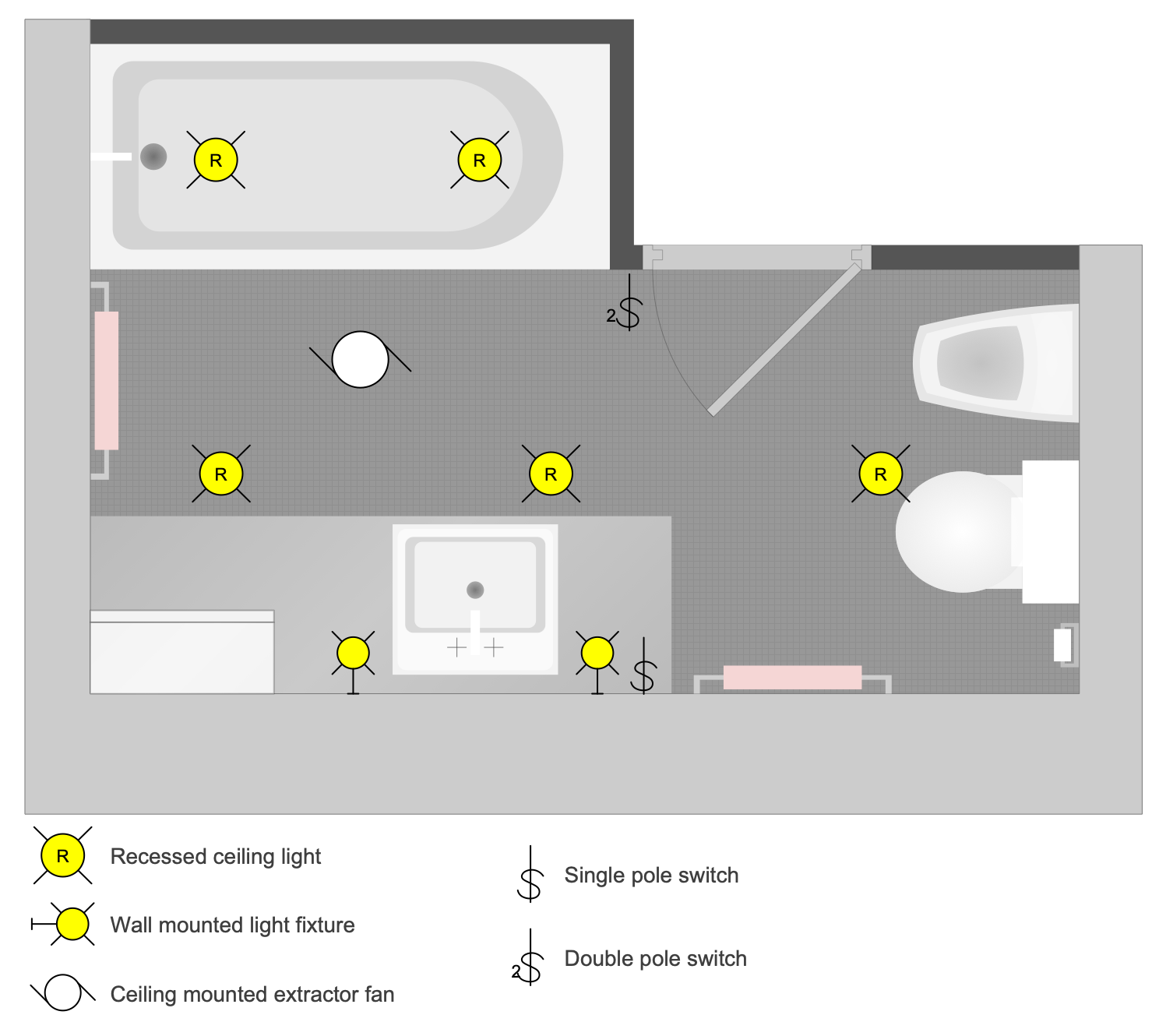
Example 7: Bathroom Lighting Plan
This diagram was created in ConceptDraw DIAGRAM using a combination of libraries from the Electric and Telecom Plans Solution and Floor Plans Solution. An experienced user spent 15 minutes creating this sample.
This sample shows a bathroom lighting plan. Bathroom lighting is important and should be uniform, bright and with minimal glare. Competently organized lighting in the bathroom allows you to comfortably take care of yourself, taking water procedures. It also plays a design role; beautiful lamps can decorate the bathroom. They are able to visually increase the space, because in most cases the bathroom is not very large. The number of lighting fixtures in the bathroom strictly depends on its area. If the room is small, usually a large luminaire in the center of the ceiling or a few recessed ceiling luminaires evenly spaced across the ceiling will suffice. Uniformity is important because good lighting is required throughout the entire bathroom space. In addition, additional lighting is usually installed near the sink and bathroom mirror. And all bathrooms’ lighting equipment must have an IP44 protection rating as safe for use in wet areas.
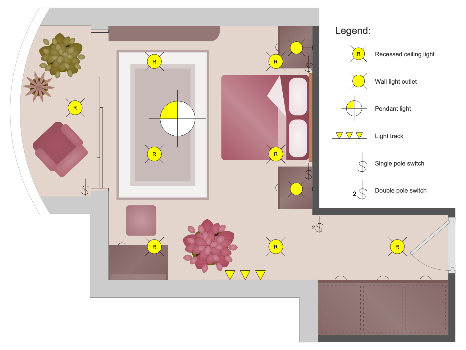
Example 8: Bedroom Lighting Plan
This diagram was created in ConceptDraw DIAGRAM using a combination of libraries from the Electric and Telecom Plans Solution and Floor Plans Solution. An experienced user spent 15 minutes creating this sample.
This sample shows bedroom lighting design, the layout of electrical luminaires, power switches, and furniture. A bedroom is a place to have a rest and relax in silence and quiet. For this reason, lighting plays a great role here. It should be calm, soft, diffused, and unobtrusive in order to create a comfortable and cozy ambience for relaxation. Lighting is one of the most important parameters for a bedroom. For general lighting, a lamp on the ceiling is usually used, but there are also areas that require separate illumination. Usually, the bedside night lamps, sconces, or floor lamps are used as additional sources of lighting, for example, for reading before sleeping, doing makeup, etc. They are placed on bedside tables, mounted on the wall at the head of the bed or near the dressing table. At the same time, lighting fixtures are also stylish interior details. Ceiling lighting in the form of individual spotlights, light tracks, or LED strips can also be used.
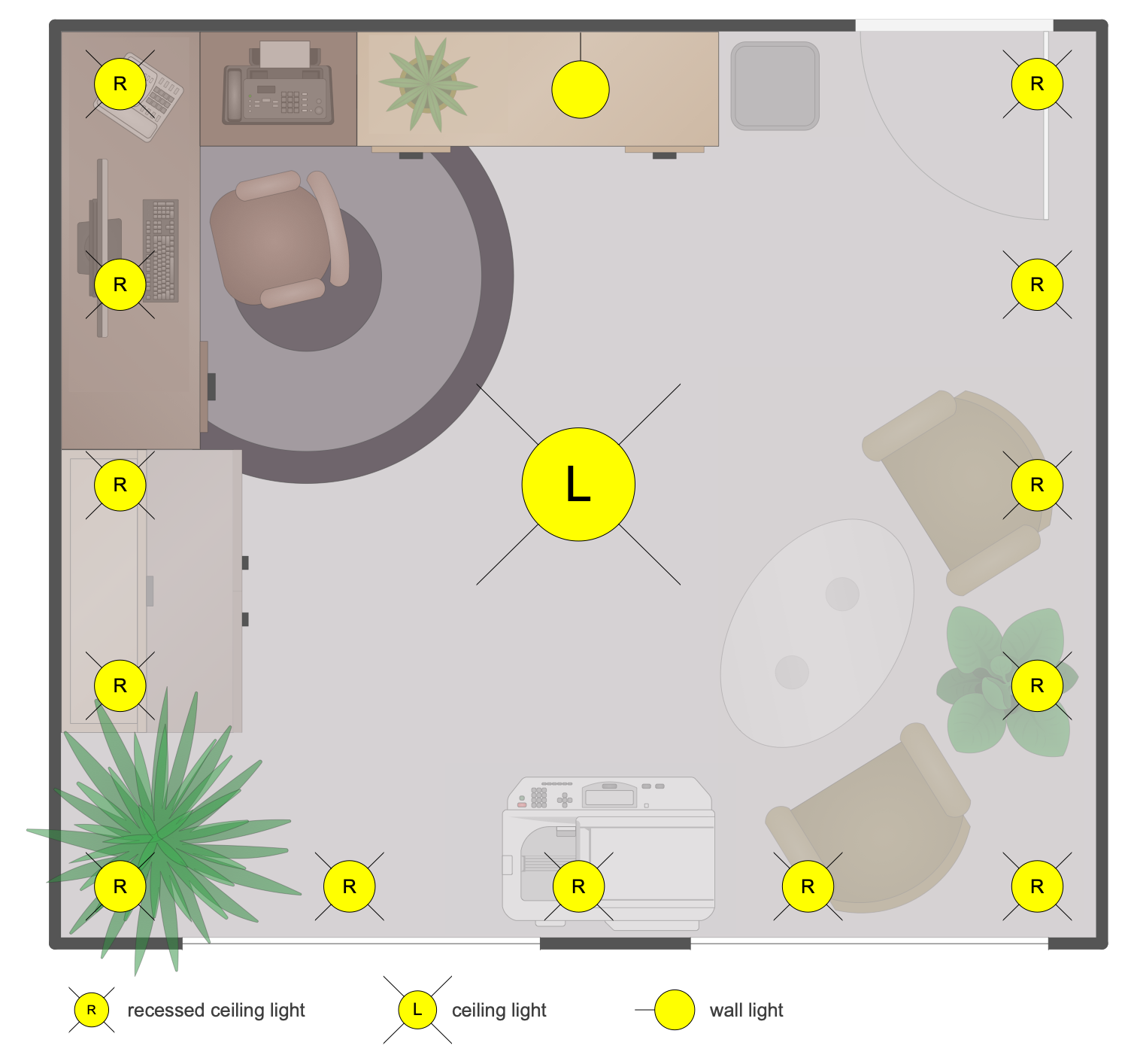
Example 9: Home Office Lighting Plan
This diagram was created in ConceptDraw DIAGRAM using a combination of libraries from the Electric and Telecom Plans Solution and Floor Plans Solution. An experienced user spent 15 minutes creating this sample.
This sample shows a home office lighting plan. Two types of lighting are needed in the home office, just like in any other room, especially those used for desk work. These are general lighting and local lighting. Good lighting is essential to reduce eye fatigue while working. General lighting replaces daylight at night, spotlights and table lamps are used to illuminate individual areas in the room. A successful combination of different types of lamps gives excellent results both for room lighting and design. The right office lighting improves performance and affects your mood. It also plays a huge aesthetic role, allows you to emphasize textures and colors, adjust the proportions in the interior. It is useful to thought-out the lighting equipment layout ahead before mounting. A detailed plan helps to avoid mistakes and choose the best arrangement. Moreover, it gives an overview how furniture and lighting will look like together.
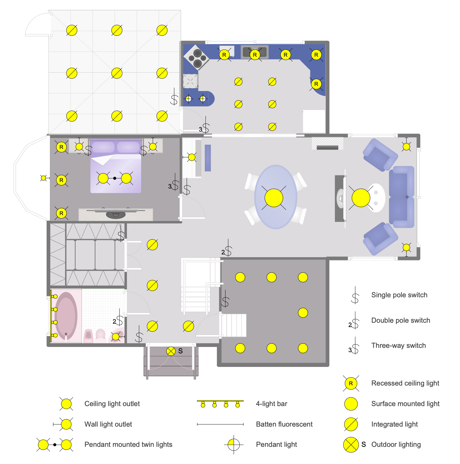
Example 10: House Lighting Plan
This diagram was created in ConceptDraw DIAGRAM using a combination of libraries from the Electric and Telecom Plans Solution and Floor Plans Solution. An experienced user spent 20 minutes creating this sample.
This floor plan example shows the lighting layout, light bulbs, and power switches for a single family home. It is built according to the plan of home furniture and includes appliances for the kitchen, bathroom and other areas. The lighting of the house directly depends on its layout, location on the cardinal points, the size of each room, the chosen style and design. Each room has its own parameters, dimensions, design and lighting requirements, generally accepted or related to personal preferences. There are also large differences in lighting design and the number of lighting fixtures associated with the purpose of the room. As a rule, a main light is mounted in each room. In addition, in some areas of the rooms, individual spotlights, sconces, and pendant lamps are used. Also, the electrical circuit of the house always includes external lighting of the adjacent territory along with internal lighting. At least, the front door to the house should be lit.
Example 11: Kitchen Lighting Plan
This diagram was created in ConceptDraw DIAGRAM using a combination of libraries from the Electric and Telecom Plans Solution and Floor Plans Solution. An experienced user spent 15 minutes creating this sample.
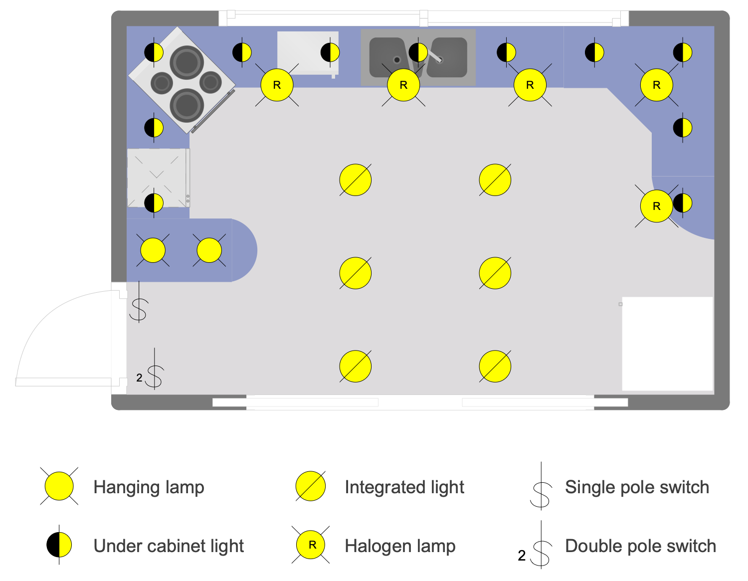
This sample shows a detailed kitchen lighting design floor plan. The arrangement of kitchen furniture and appliances including kitchen cabinets, sink, stove, oven, and refrigerator is also shown. The lighting plan depicts the layout of electrical luminaires and power switches. There are integrated lights, halogen lamps, hanging lamps, under cabinet lights. The switches of two types are envisaged — single and double pole. The kitchen has a U shape and this defines the arrangement of lighting of a working area. The halogen lamps are arranged along with the kitchen cabinets and strictly repeat their shape. The area of a bar rack is lighted with hanging lamps and it is the most popular way to highlight this area. The design of the hanging lamps allows giving exclusivity to the design of the entire room. At the moment, there is a great selection of different types of lamps and the choice is only yours. Just add a dining table with chairs in this plan and you will get a fully ready plan of kitchen furniture and lighting.
Example 12: Living Room Lighting Plan
This diagram was created in ConceptDraw DIAGRAM using a combination of libraries from the Electric and Telecom Plans Solution and Floor Plans Solution. An experienced user spent 15 minutes creating this sample.
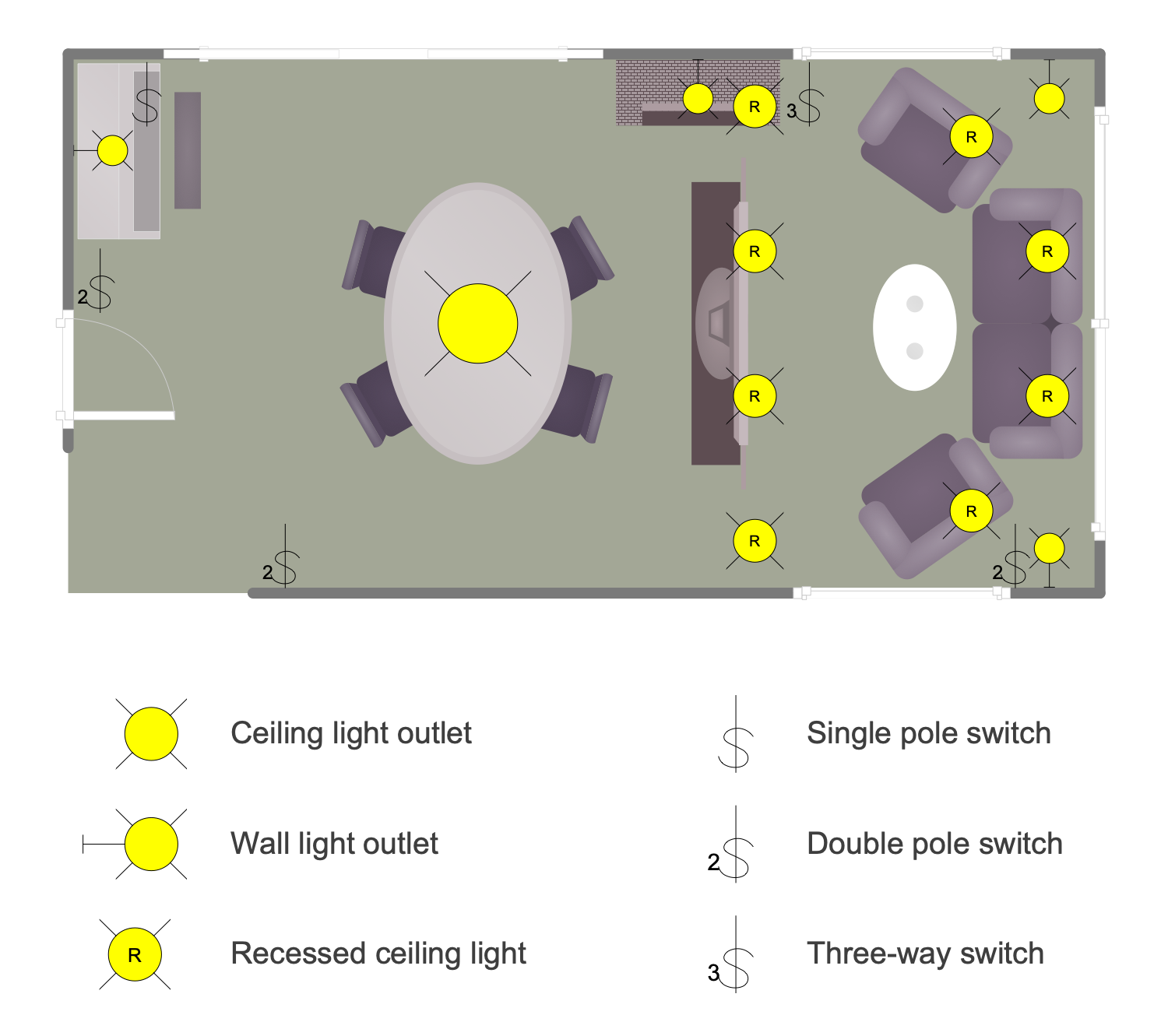
This sample shows a living room lighting design floor plan. The furnishings arrangement is also included. It is a good way because the arrangement of furniture and lighting appliances is closely related. This plan gives an overall overview of a room design, how the furniture and lighting are combined and look together. The living room is a large room for relaxation, communication of all family members and spending free time together. The plan shows a typical living room. It is divided into two areas — a dining area and a living area. Lighting is also distributed across areas. A ceiling lamp is placed above the table in the dining area. Several recessed ceiling lights are located in the seating area above the TV and soft furnishings. There are also sockets in different parts of this living room and three types of switches: single pole, double pole and three pole.
Example 13: Office Lighting Plan
This diagram was created in ConceptDraw DIAGRAM using a combination of libraries from the Electric and Telecom Plans Solution and Floor Plans Solution. An experienced user spent 25 minutes creating this sample.
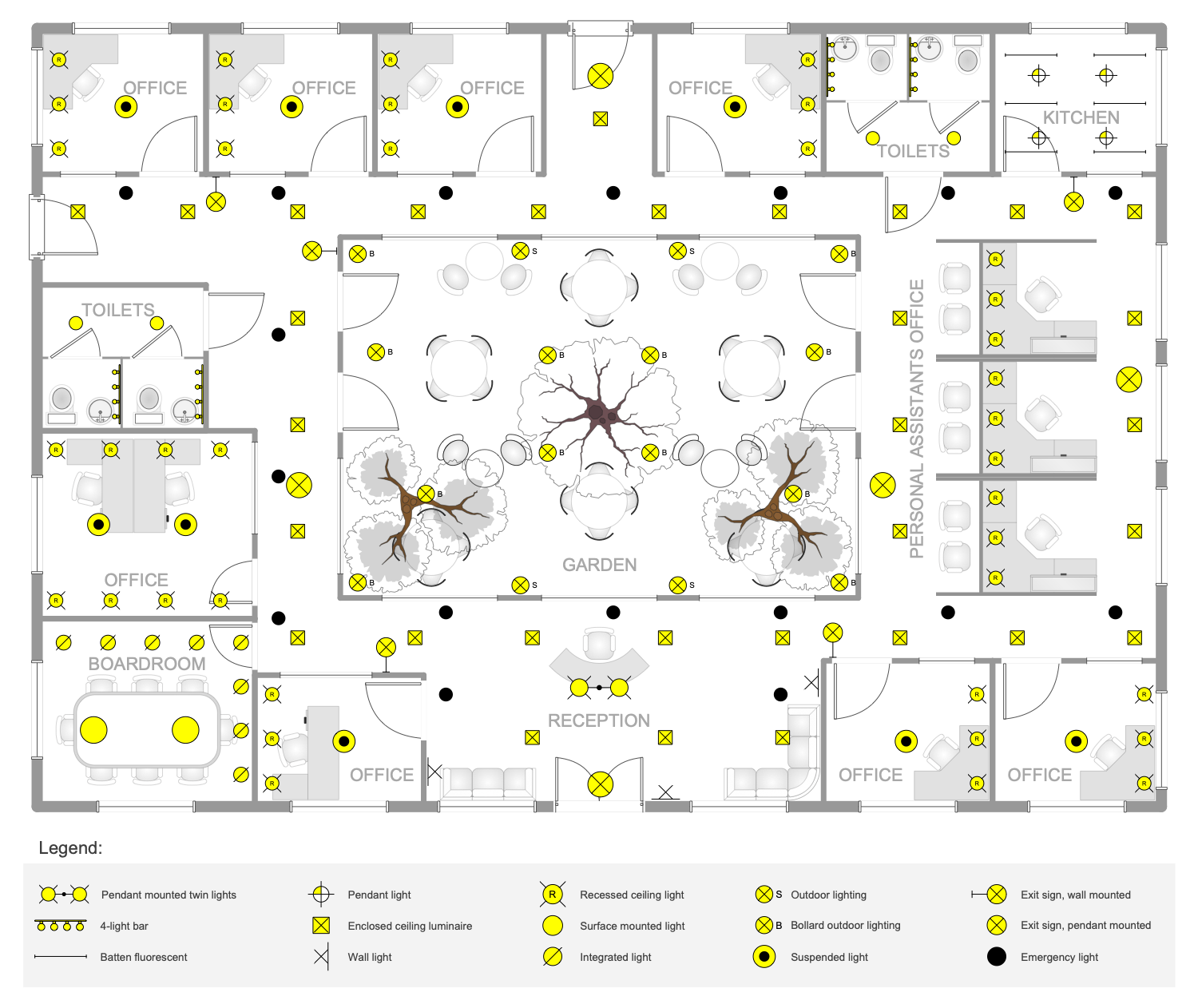
This example lighting plan shows the location of furniture, appliances, electric lights, and power switches on the office floor plan. This is a plan of a large office with many rooms, a kitchen, a conference room, a large hall with a reception, and even a garden in the middle of the floor. Lighting is a really important point for any space, especially offices and workers where people spend a lot of time. At the same time, it is important to correctly and efficiently organize the lighting, to carefully consider the location of the lamps before installing them. Lighting strongly affects labor productivity, performance, mood and concentration. With the right choice, it can significantly improve productivity. Even if you have a small office, you can visually correct it by applying light colors in the design of the room and good lighting. A successful combination of different types of luminaires, such as ceiling, wall, recessed, integrated, etc., is a successful design solution and a convenient way to control lighting.
Example 14: Restaurant Lighting Plan
This diagram was created in ConceptDraw DIAGRAM using a combination of libraries from the Electric and Telecom Plans Solution and Floor Plans Solution. An experienced user spent 25 minutes creating this sample.
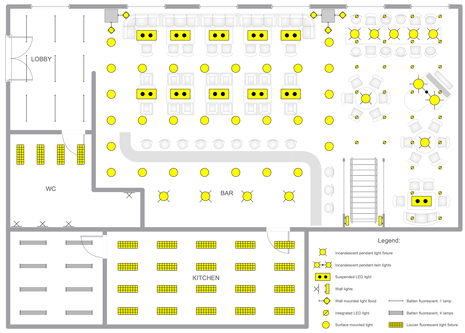
This electrical floor plan is for a restaurant. It was built according to the plan of the restaurant. Aside from food and service, restaurants vary greatly in size, appearance, ambiance, and more. This sample shows a large restaurant with several rooms. This room has a lobby, bar, main hall and lounge with a grand piano. The areas are visually separated by surface-mounted luminaires. Usually restaurants should be able to dim the light intensity. The intensity can also vary from one area to another, creating relaxation places with soft lighting. Incandescent pendant lights or LED pendant lights are used to illuminate tables. Lighting in the kitchen and in the pantry is organized by louvered fluorescent lamps and lattice fluorescent 4-lamp lights, respectively. This plan is also useful as a basis for creating a restaurant's second floor lighting plan in minutes and no sweat.
Inside
What I Need to Get Started
Both ConceptDraw DIAGRAM diagramming and drawing software and the Electric and Telecom Plans solution can help creating the floor plans you need. The Electric and Telecom Plans solution can be found in the Building Plans area of ConceptDraw STORE application that can be downloaded from this site. Make sure that both ConceptDraw DIAGRAM and ConceptDraw STORE applications are installed on your computer before you get started.
How to install
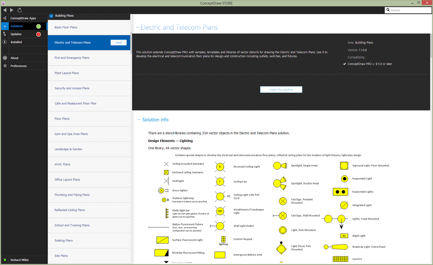
After ConceptDraw STORE and ConceptDraw DIAGRAM are downloaded and installed, you can install the Electric and Telecom Plans solution from the ConceptDraw STORE.
Start using
To make sure that you are doing it all right, use the pre-designed symbols from the stencil libraries from the solution to make your drawings look smart and professional. Also, the pre-made examples from this solution can be used as drafts so your own drawings can be based on them. Using the samples, you can always change their structures, colors and data.
