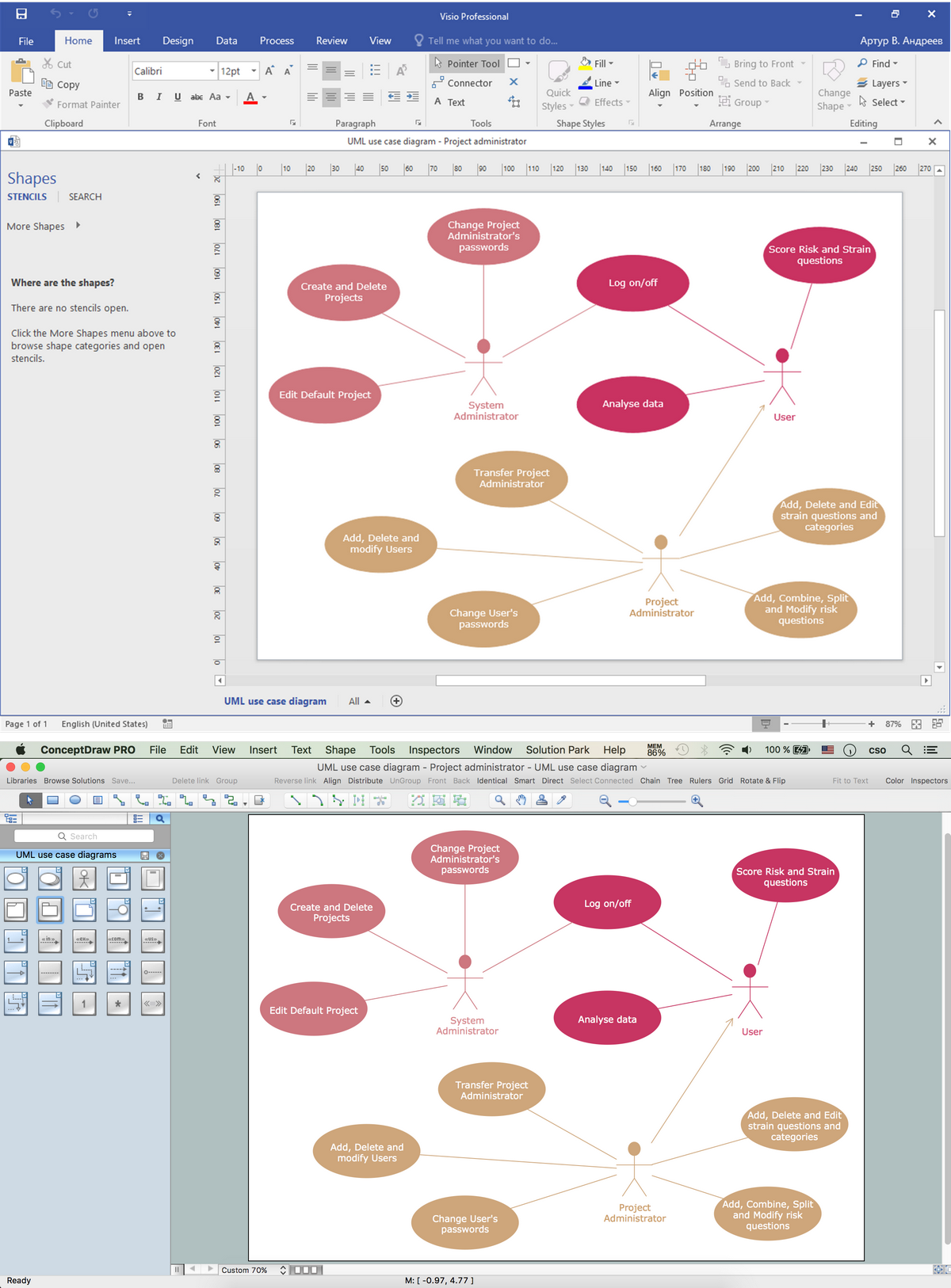
Use Case Diagrams technology with ConceptDraw PRO
Use case diagrams are used at the development of software and systems for definition of functional system requirements or system of systems. Use case diagram presents the consecution of object’s actions (user’s or system’s) which are executed for reaching the definite result.HelpDesk
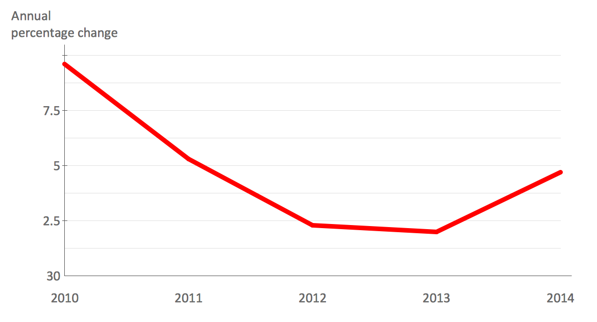
How to Draw a Line Chart Quickly
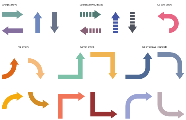
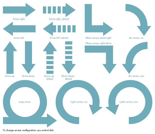
A common line chart is a graphical representation of the functional relationship between two series of data. A line chart that is created by connecting a series of data points together with a straight line is the most basic type of a line chart. A line chart can be used for depicting data that changes continuously over time. It is extensively utilized in statistics, marketing and financial business. ConceptDraw Line Graph solution provides the possibility to make 2D line charts quickly and effortlessly.The vector stencils library "Workflow arrows" contains 21 arrow shapes.
Use it to design your business process workflow diagrams with ConceptDraw PRO software.
The shapes example "Design elements - Workflow arrows" is included in the Business Process Workflow Diagrams solution from the Business Processes area of ConceptDraw Solution Park.
Use it to design your business process workflow diagrams with ConceptDraw PRO software.
The shapes example "Design elements - Workflow arrows" is included in the Business Process Workflow Diagrams solution from the Business Processes area of ConceptDraw Solution Park.
Garrett IA Diagrams with ConceptDraw PRO
Garrett IA diagrams are used at development of Internet-resources, in particulars at projecting of interactions of web-resource elements. The diagram of information architecture of the web resource which is constructed correctly with necessary details presents to developers the resource in comprehensible and visual way.The vector stencils library "Scrum arrows" contains 15 shapes.
Use it to design your agile software development diagrams and scrum infographics with ConceptDraw PRO software.
"Agile software development is a set of principles for software development in which requirements and solutions evolve through collaboration between self-organizing, cross-functional teams. It promotes adaptive planning, evolutionary development, early delivery, and continuous improvement, and it encourages rapid and flexible response to change. Agile itself has never defined any specific methods to achieve this, but many have grown up as a result and have been recognized as being 'Agile'." [Agile software development. Wikipedia]
The diagram shapes sample "Design elements - Scrum arrows" is included in the Scrum solution from the Project Management area of ConceptDraw Solution Park.
IDEF3 Standard
Use Case Diagrams technology. IDEF3 Standard is intended for description and further analysis of technological processes of an enterprise. Using IDEF3 standard it is possible to examine and model scenarios of technological processes.Visio Files and ConceptDraw
Visio Files and ConceptDraw. ConceptDraw PRO is compatible with MS Visio .VDX formatted files.VDX is Visio’s open XML file format, and it can be easily imported and exported by ConceptDraw PRO.The vector stencils library "Transport map" contains 96 pictograms for drawing transport maps.
Use it in your spatial infographics for visual representation of transport schemes and plans as metro maps in the ConceptDraw PRO diagramming and vector drawing software extended with the Spatial Infographics solution from the area "What is Infographics" of ConceptDraw Solution Park.
Use it in your spatial infographics for visual representation of transport schemes and plans as metro maps in the ConceptDraw PRO diagramming and vector drawing software extended with the Spatial Infographics solution from the area "What is Infographics" of ConceptDraw Solution Park.
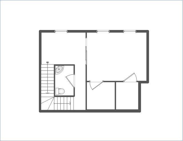
Use this template to develop the home layouts, space plans, interior design, kitchen and bathroom design, architectural and construction documents using ConceptDraw PRO diagramming and vector drawing software.
"A floor plan is the most fundamental architectural diagram, a view from above showing the arrangement of spaces in building in the same way as a map, but showing the arrangement at a particular level of a building. Technically it is a horizontal section cut through a building (conventionally at three feet / one metre above floor level), showing walls, windows and door openings and other features at that level. The plan view includes anything that could be seen below that level: the floor, stairs (but only up to the plan level), fittings and sometimes furniture. Objects above the plan level (e.g. beams overhead) can be indicated as dotted lines." [Architectural drawing. Wikipedia]
The Home floor plan template is included in the Floor Plans solution from the Building Plans area of ConceptDraw Solution Park.
www.conceptdraw.com/ solution-park/ floor-plans
- Organizational Charts with ConceptDraw PRO | Basic Flowchart ...
- Organizational Charts with ConceptDraw PRO | Basic Flowchart ...
- IDEF0 standard with ConceptDraw PRO | What Is Dotted And Thick ...
- Dotted Arrow Line
- Dotted Arrow
- Dotted Arrow Diagram
- Dotted Arrow Lines
- Basic Flowchart Symbols and Meaning | Use Case Diagrams ...
- Png Photoshop Architecture Arrows Doted Lines
- Dotted Curves Arrow Png
- How to Draw a Circular Arrows Diagram Using ConceptDraw PRO ...
- Dotted Line Connectors
- Curved Dotted Arrow Png
- Dotted Box In Erd
- How to Draw a Circular Arrows Diagram Using ConceptDraw PRO ...
- How to Draw a Line Chart Quickly | Export from ConceptDraw PRO ...
- Flowchart Dotted Line
- Dotted Line Process Map
- How I Represent Dashed Line Notation In Straight Line

