"Surround sound is a technique for enriching the sound reproduction quality of an audio source with additional audio channels from speakers that surround the listener (surround channels), providing sound from a 360° radius in the horizontal plane (2D) as opposed to "screen channels" (centre, [front] left, and [front] right) originating only from the listener's forward arc.
Surround sound is characterized by a listener location or sweet spot where the audio effects work best, and presents a fixed or forward perspective of the sound field to the listener at this location. The technique enhances the perception of sound spatialization by exploiting sound localization; a listener's ability to identify the location or origin of a detected sound in direction and distance. Typically this is achieved by using multiple discrete audio channels routed to an array of loudspeakers.
There are various surround sound based formats and techniques, varying in reproduction and recording methods along with the number and positioning of additional channels." [Surround sound. Wikipedia]
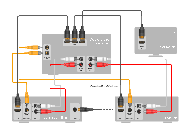
The hookup diagram example "Hook up drawing - Home entertainment system with surround sound" was created using the ConceptDraw PRO diagramming and vector drawing software extended with the Audio and Video Connectors solution from the Engineering area of ConceptDraw Solution Park.
The design elements library "Cable TV" contains 64 symbols of CATV network equipment.
"Cable television is a system of distributing television programs to subscribers via radio frequency (RF) signals transmitted through coaxial cables or light pulses through fiber-optic cables. This contrasts with traditional broadcast television (terrestrial television) in which the television signal is transmitted over the air by radio waves and received by a television antenna attached to the television. FM radio programming, high-speed Internet, telephone service, and similar non-television services may also be provided through these cables.
The abbreviation CATV is often used for cable television." [Cable television. Wikipedia]
Use the shapes library "Cable TV" to draw CATV system design floor plans, network topology diagrams, wiring diagrams and cabling layout schemes using the ConceptDraw PRO diagramming and vector drawing software.
The vector stencils library "Cable TV" is included in the Electric and Telecom Plans solution from the Building Plans area of ConceptDraw Solution Park.
Network Diagram Examples
Network diagram is a chart which represents nodes and connections between them in computer network or any telecommunication network, it is a visual depiction of network architecture, physical or logical network topology. There are used common icons for the Network diagrams design, such as icons of various network appliances, computer devices, routers, clouds, peripheral devices, digital devices, etc. Network diagrams can represent networks of different scales (LAN level, WAN level) and detailization. ConceptDraw DIAGRAM diagramming software enhanced with Computer Network Diagrams solution from Computer and Networks area includes huge collection of computer and network templates, design objects and stencils, and numerous quantity of Network diagram examples and samples, among them: Basic Computer Network Diagrams, Communication Network Diagram, Wireless Router Network Diagram, LAN Topology Diagram, Computer Network System Design Diagram, Mobile Satellite Communication Network, Web-based Network Diagram, Hybrid Network Diagram, and many others.
- Mobile satellite TV network diagram | CCTV Surveillance System ...
- Basic CCTV System Diagram . CCTV Network Diagram Example ...
- Network Tv Drawing
- Mobile satellite TV network diagram | CCTV Surveillance System ...
- Communication medium diagram | Basic CCTV System Diagram ...
- Audiovisual system hook up diagram - Template | How To use ...
- How To Create CCTV Network Diagram | CCTV Network Example ...
- Cctv Camera System Drawing
- CCTV Network Example | CCTV Network Diagram Software | Basic ...
- CCTV Surveillance System Diagram . CCTV Network Diagram ...
- How to Create a CCTV Diagram in ConceptDraw PRO | CCTV ...
- CCTV Network Example | Basic CCTV System Diagram . CCTV ...
- CCTV Surveillance System Diagram . CCTV Network Diagram ...
- CCTV Surveillance System Diagram . CCTV Network Diagram ...
- Drawing Satellite Diagram
- CCTV Surveillance System Diagram . CCTV Network Diagram ...
- CCTV Network Diagram Software | Basic CCTV System Diagram ...
- How to Create a CCTV Diagram in ConceptDraw PRO | How To ...
- Security and Access Plans | CCTV Surveillance System Diagram ...

.png--diagram-flowchart-example.png)
