The vector stencils library "Network layout floorplan" contain 34 symbol icons for drawing computer network floor plans, communication equipment layouts, and structured cabling diagrams.
"Structured cabling is building or campus telecommunications cabling infrastructure that consists of a number of standardized smaller elements (hence structured) called subsystems. ...
Structured cabling design and installation is governed by a set of standards that specify wiring data centers, offices, and apartment buildings for data or voice communications using various kinds of cable, most commonly category 5e (CAT-5e), category 6 (CAT-6), and fibre optic cabling and modular connectors. These standards define how to lay the cabling in various topologies in order to meet the needs of the customer, typically using a central patch panel (which is normally 19 inch rack-mounted), from where each modular connection can be used as needed. Each outlet is then patched into a network switch (normally also rack-mounted) for network use or into an IP or PBX (private branch exchange) telephone system patch panel." [Structured cabling. Wikipedia]
The design elements example "Network layout floorplan - Vector stencils library" was created using the ConceptDraw PRO diagramming and vector drawing software extended with the Network Layout Floor Plans solution from the Computer and Networks area of ConceptDraw Solution Park.
HelpDesk
How to Connect Objects in ConceptDraw PRO on PC
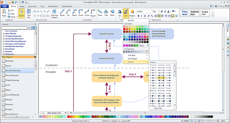
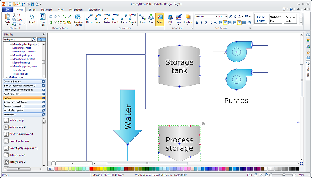
ConceptDraw PRO provides a few options for drawing connections between objects: Direct Connectors, Smart, Arc, Bezier, Curve and Round Connectors. You can connect objects in your ConceptDraw diagram with proper connectors using the embedded automatic connection modes. This article describes how you can connect objects with connectors and how you can ascribe different types and behaviors.
HelpDesk
How to Create a Floor Plan Using ConceptDraw PRO
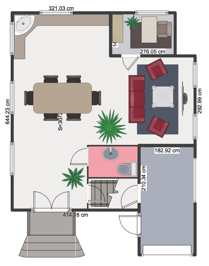
Making a floor plan is the best way to get a handle on how to organize your living space, and find out what could be changed. Creating a floor plan to scale is a challenge of the home and interior design process and can be noticeably helpful for visualizing things like furniture layout. You can use ConceptDraw PRO to produce layouts of real estate properties. ConceptDraw PRO contains the large quantity of pre-designed vector objects that you can use for quick and easy designing such floor plans. You can easily determine the size of the rooms and distances in you drawing. The ability to create a floor plan is delivered by the Floor Plans solution. This solution extends ConceptDraw PRO with libraries that contains over 500 objects of floor plan elements. There is a set of special objects that displays the sizes, corners, squares and other technical details using the current measurements of units.HelpDesk
How to Simplify Flow Charting in ConceptDraw PRO on Windows
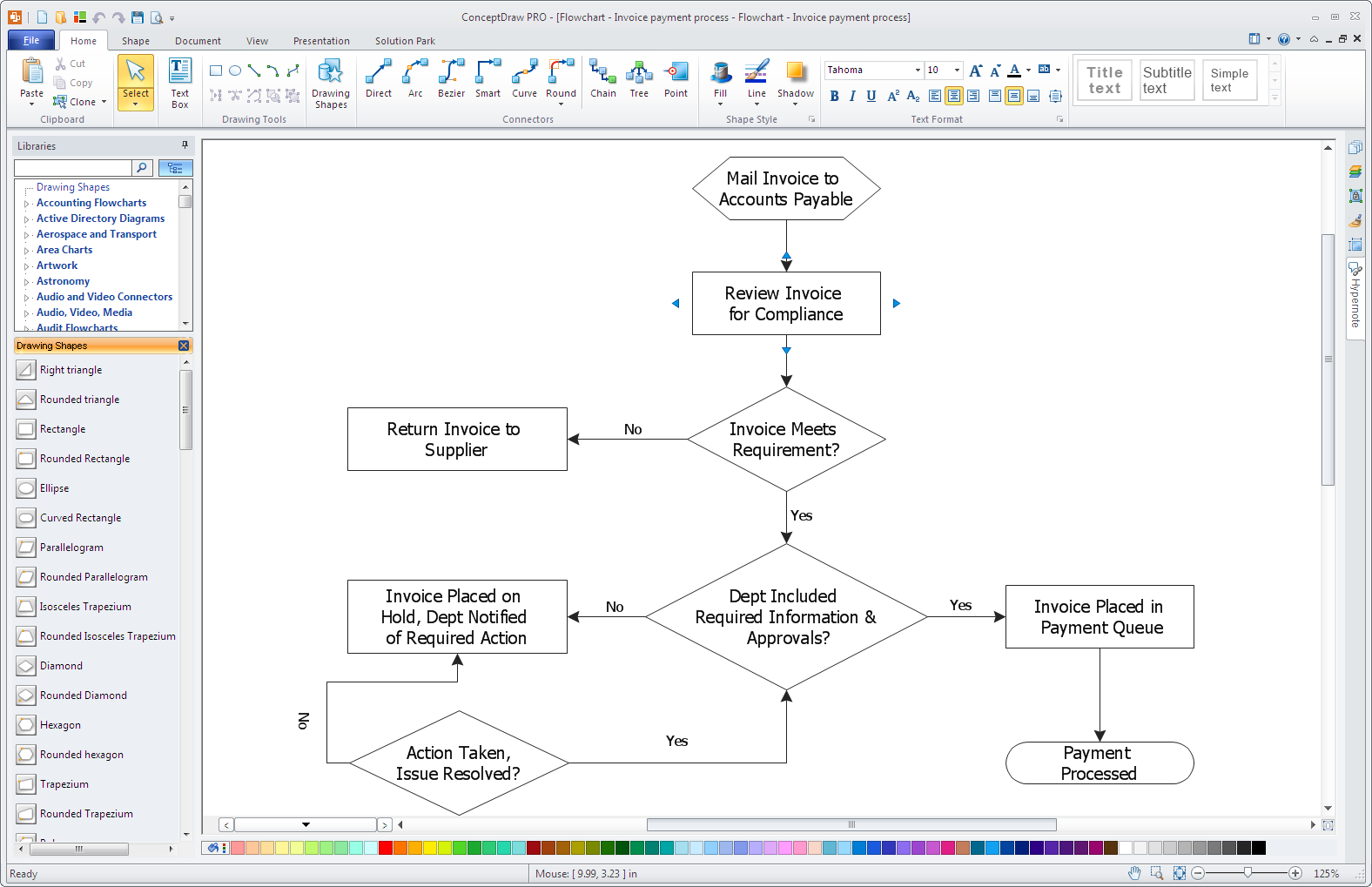
Flowcharts are a best tool for staking out a huge and complex process into some small readable parts. The use of standard symbols that make it clear for a wide audience makes a software tool preferred for this task. The core for a successful flowchart is its simplicity. That is why often before beginning making flowchart through software, people draw the scetch on a piece of paper. Designing an effective flowchart means the combination of the data needed to be shown and the simplicity with which you depict it. In ConceptDraw PRO it really is sp simple to draw even the most complex flowcharts. Use the RapidDraw technology for the best results.HelpDesk
How to Apply Layers For a ConceptDraw Drawing on PC
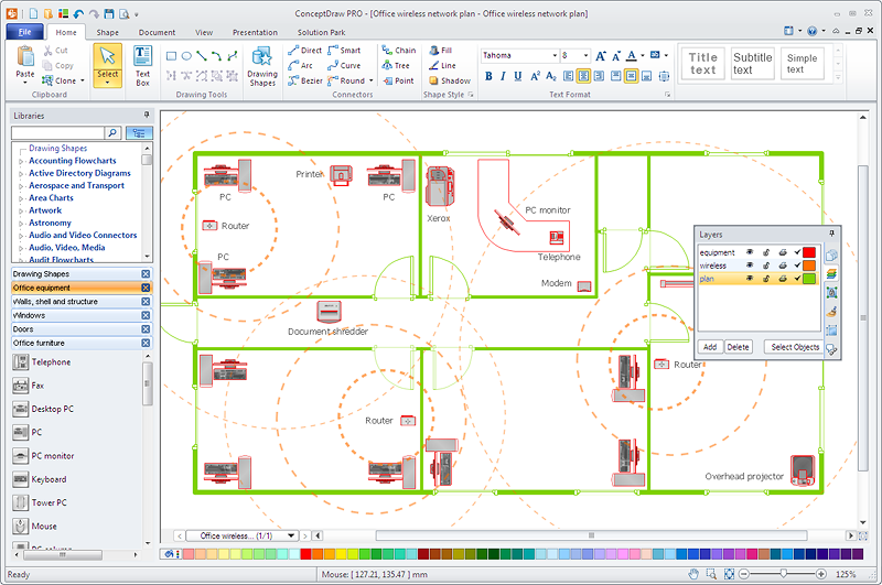
Tips on how to use ConceptDraw PRO Layers on WindowsHelpDesk
How to Add, Move, or Delete Connection Points in ConceptDraw PRO on PC
Few tips on how to manage connection points in ConceptDraw PRO drawings. A connection point is a special point on an object that allows one to connect a connector. You can add connection points to any object or to a blank area in your document.HelpDesk
How to Edit Grouped Shapes in ConceptDraw PRO on Windows
ConceptDraw PRO allows one to group objects. Grouping shapes, pictures, or objects lets you style, format, rotate, and move them together, as though they were a single object. At the same time, you can edit each of them separately.HelpDesk
How to Edit Drawing Using Shadows in ConceptDraw PRO
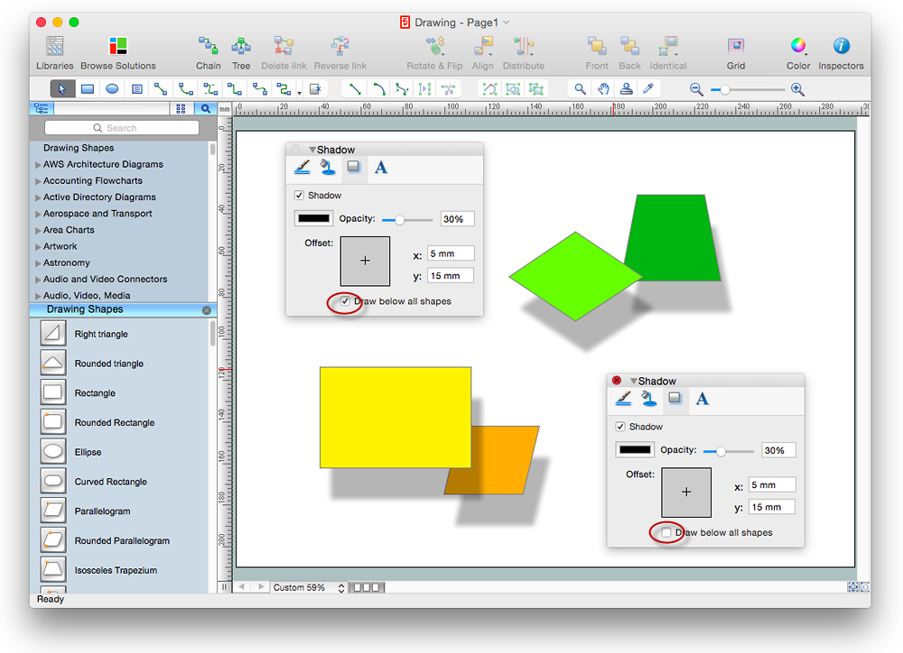
Tips on how to apply shadow to objects in the ConcepDraw drawing- Design elements - Doors and windows | Restaurant Floor Plans ...
- Home floor plan template | Architectural Drawing Of Casement ...
- Create Floor Plans easily with ConceptDraw PRO! | Building ...
- How to Create a Floor Plan for the Classroom | Classroom Seating ...
- Cafe plan | Cafe Floor Plans | Café Floor Plan Design Software
- How to Draw a Security and Access Floor Plan | Security and Access ...
- How to Draw a Security and Access Floor Plan | How To Draw ...
- Design elements - Network layout floorplan | How To Create ...
- How to Draw a Security and Access Floor Plan | Security and Access ...
- Ethernet local area network layout floor plan | Network Layout Floor ...
- How To Create Restaurant Floor Plan in Minutes | Create Floor ...
- How to Draw a Security and Access Floor Plan | How To Draw ...
- How To Create Restaurant Floor Plan in Minutes | Cafe and ...
- Factory layout floor plan
- How To Create Restaurant Floor Plan in Minutes | Restaurant Floor ...
- Design elements - Doors and windows | Security system floor plan ...
- Drawing Floorplan Meeting Room Free Software
- How to Create a Reflected Ceiling Floor Plan | Reflected Ceiling ...
- Café Floor Plan Design Software | Cafe Floor Plans | How To Create ...
- Cafe and Restaurant Floor Plan | How To Create Restaurant Floor ...


