How To use House Electrical Plan Software


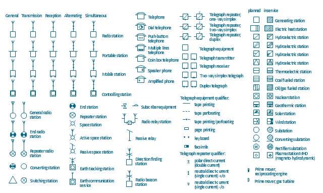
The vector stencils library "Stations" contains 110 symbols of communications equipment, generating, transmitting and receiving stations; substations; satellites; and power plants for power generation and distribution and radio relay systems.
"A power station (also referred to as a generating station, power plant, powerhouse or generating plant) is an industrial facility for the generation of electric power. At the center of nearly all power stations is a generator, a rotating machine that converts mechanical power into electrical power by creating relative motion between a magnetic field and a conductor. The energy source harnessed to turn the generator varies widely. It depends chiefly on which fuels are easily available, cheap enough and on the types of technology that the power company has access to. Most power stations in the world burn fossil fuels such as coal, oil, and natural gas to generate electricity, and some use nuclear power, but there is an increasing use of cleaner renewable sources such as solar, wind, wave and hydroelectric." [Power station. Wikipedia]
"Radio broadcasting is a one-way wireless transmission over radio waves intended to reach a wide audience. Stations can be linked in radio networks to broadcast a common radio format, either in broadcast syndication or simulcast or both. Audio broadcasting also can be done via cable radio, local wire television networks, satellite radio, and internet radio via streaming media on the Internet.
The signal types can be either analog audio or digital audio." [Radio broadcasting. Wikipedia]
The shapes example "Design elements - Stations" was drawn using the ConceptDraw PRO diagramming and vector drawing software extended with the Electrical Engineering solution from the Engineering area of ConceptDraw Solution Park.
Power and radio station symbols
 Electrical Engineering
This solution extends ConceptDraw PRO v.9.5 (or later) with electrical engineering samples, electrical schematic symbols, electrical diagram symbols, templates and libraries of design elements, to help you design electrical schematics, digital and analog
 ConceptDraw Solution Park
ConceptDraw Solution Park collects graphic extensions, examples and learning materials
The vector stencils library "Transmission paths" contains 43 symbols of power transmission paths, electronic circuits, bus connectors and elbows, terminals, junctions, and concentrators.
Use it to annotate electrical diagrams, electronic schematics and circuit diagrams.
"A physical medium in data communications is the transmission path over which a signal propagates.
Many transmission media are used as communications channel.
For telecommunications purposes in the United States, Federal Standard 1037C, transmission media are classified as one of the following:
(1) Guided (or bounded) - waves are guided along a solid medium such as a transmission line.
(2) Wireless (or unguided) - transmission and reception are achieved by means of an antenna.
One of the most common physical medias used in networking is copper wire. Copper wire to carry signals to long distances using relatively low amounts of power. The unshielded twisted pair (UTP) is eight strands of copper wire, organized into four pairs.
Another example of a physical medium is optical fiber, which has emerged as the most commonly used transmission medium for long-distance communications. Optical fiber is a thin strand of glass that guides light along its length.
Multimode and single mode are two types of commonly used optical fiber. Multimode fiber uses LEDs as the light source and can carry signals over shorter distances, about 2 kilometers. Single mode can carry signals over distances of tens of miles.
Wireless media may carry surface waves or skywaves, either longitudinally or transversely, and are so classified.
In both communications, communication is in the form of electromagnetic waves. With guided transmission media, the waves are guided along a physical path; examples of guided media include phone lines, twisted pair cables, coaxial cables, and optical fibers. Unguided transmission media are methods that allow the transmission of data without the use of physical means to define the path it takes. Examples of this include microwave, radio or infrared. Unguided media provide a means for transmitting electromagnetic waves but do not guide them; examples are propagation through air, vacuum and seawater.
The term direct link is used to refer to the transmission path between two devices in which signals propagate directly from transmitters to receivers with no intermediate devices, other than amplifiers or repeaters used to increase signal strength. This term can apply to both guided and unguided media.
A transmission may be simplex, half-duplex, or full-duplex.
In simplex transmission, signals are transmitted in only one direction; one station is a transmitter and the other is the receiver. In the half-duplex operation, both stations may transmit, but only one at a time. In full duplex operation, both stations may transmit simultaneously. In the latter case, the medium is carrying signals in both directions at same time." [Transmission medium. Wikipedia]
The shapes example "Design elements - Transmission paths" was drawn using the ConceptDraw PRO diagramming and vector drawing software extended with the Electrical Engineering solution from the Engineering area of ConceptDraw Solution Park.
Transmission path symbols

The vector stencils library "Cable TV" contains 64 symbols of cable TV network equipment.
Use these shapes for drawing CATV system design floor plans, network topology diagrams, wiring diagrams and cabling layout schemes in the ConceptDraw PRO diagramming and vector drawing software.
The vector stencils library "Cable TV" is included in the Electric and Telecom Plans solution from the Building Plans area of ConceptDraw Solution Park.
Output Directional Tap 1

Output Directional Tap 2

Output Directional Tap 3

Output Directional Tap 4

Output Directional Tap 5

2-way Splitter

3-way Splitter

4-way Splitter

AC Power Block

Bond

Down Guy

Building Guy and Anchor

Rock Guy with Anchor

Down Guy with Anchor

Pole-to-Pole Guy

Sidewalk Down Guy with Anchor

Sidewalk Down Guy

Slack Span Messenger Wire

Tensioned Messenger Wire w/out cable

Tensioned Messenger Wire

Ground

Joint Usage (Power & Telephone Pole)
-cable-tv---vector-stencils-library.png--diagram-flowchart-example.png)
Joint Usgae Pole with Transformer

Strut

Tree Guy with Anchor

Push Brace (smaller pole in actual relative position)
-cable-tv---vector-stencils-library.png--diagram-flowchart-example.png)
Extension Arm

Built CATV Pole

Proposed CATV Pole

Directional Tap 1

Directional Tap 2

Manhole

Telephone Pole

Riser Pole

Vault Handheld

Fixed Equalizer

Fixed Flat Attenuators

Other Supporting Structures

Pedestal - Underground Routing

Power Pole

Direct Buried Underground Routing

Duct Line Underground Routing

Line Terminations

2-Way Optical Splice Location

3-Way Optical Splice Location

4-Way Optical Splice Location

> 4-Way Optical Splice Location

Optical Amplifier

Cable AC Power Combiner

Optical Fiber Cable

Optical Connector

Wavelength Demultiplexer

Wavelength Multiplexer

Optical Transmitter

Optical Transmitter

Optical Node

Optical Splitter

Headend (Signal Processing)
-cable-tv---vector-stencils-library.png--diagram-flowchart-example.png)
Node

Primary Hub

Secondary Hub

Coaxial Splice

Power Supply

Variable Equalizer

Circuits and Logic Diagram Software

 Mechanical Engineering
This solution extends ConceptDraw PRO v.9 mechanical drawing software (or later) with samples of mechanical drawing symbols, templates and libraries of design elements, for help when drafting mechanical engineering drawings, or parts, assembly, pneumatic,
 Active Directory Diagrams
Active Directory Diagrams solution significantly extends the capabilities of ConceptDraw PRO software with special Active Directory samples, convenient template and libraries of Active Directory vector stencils, common icons of sites and services, icons of LDPA elements, which were developed to help you in planning and modelling network structures and network topologies, in designing excellently looking Active Directory diagrams, Active Directory Structure diagrams, and Active Directory Services diagram, which are perfect way to visualize detailed structures of Microsoft Windows networks, Active Directory Domain topology, Active Directory Site topology, Organizational Units (OU), and Exchange Server organization.
Technical Drawing Software

Network Glossary Definition


The vector stenvils library "Outlets" contains 57 symbols of electrical outlets.
Use these shapes for drawing building interior design, electrical floor plans and layouts of AC power plugs and sockets in the ConceptDraw PRO diagramming and vector drawing software.
The vector stencils library "Outlets" is included in the Electric and Telecom Plans solution from the Building Plans area of ConceptDraw Solution Park.
Single Outlet

Single Outlet and Switch

Emergency Circuit Single Outlet

Duplex Convenience Outlet

Emergency Circuit Duplex Outlet

Weatherproof Convenience Outlet

Range Outlet

Switch and Convenience Outlet

Radio and Convenience Outlet

Radio Outlet

Dedicated Duplex Outlet

Duplex Ground Fault Interrupter

Split Wired Duplex Outlet

240v Outlet

Floor Mounted Outlet

Floor Special-purpose Outlet

Heavy Duty Outlet

Heavy Duty Outlet with Convenience Outlet

Triplex Outlet

Split Wired Triplex Outlet

Quadruplex Outlet

Emergency Circuit Quadruplex Outlet

Special-purpose Outlet

Duplex Special-purpose Outlet

Special-purpose connection or provision for connection

Multi-outlet Assembly

Data/voice, Power Floor Mounted Outlet

Clock Hanger Outlet, Mounted

Blanked Outlet

Drop Outlet

Electrical Outlet

Fan Outlet

Junction Box

Lamp Holder

Lamp holder with pull switch

Pull Switch

Vapor discharge lamp outlet

Exit Light Outlet

Floor Receptacle

Telephone outlet

Floor Phone Outlet

Wall Phone Outlet

Weatherproof Phone Outlet

Phone Feed

Computer Data Outlet

Television outlet

Floor TV Outlet

TV Feed

Weatherproof TV Outlet

TV and Phone Outlet

Door Phone Outlet

Fax Outlet

Fiber Outlet

Multi-Purpose Outlet

Local Area Network Outlet

Wall Mounted Data Outlet

Wall Mounted Data/Telephone Outlet

 Computer Network Diagrams
Computer Network Diagrams solution extends ConceptDraw PRO software with samples, templates and libraries of vector icons and objects of computer network devices and network components to help you create professional-looking Computer Network Diagrams, to plan simple home networks and complex computer network configurations for large buildings, to represent their schemes in a comprehensible graphical view, to document computer networks configurations, to depict the interactions between network's components, the used protocols and topologies, to represent physical and logical network structures, to compare visually different topologies and to depict their combinations, to represent in details the network structure with help of schemes, to study and analyze the network configurations, to communicate effectively to engineers, stakeholders and end-users, to track network working and troubleshoot, if necessary.
 Fault Tree Analysis Diagrams
This solution extends ConceptDraw PRO v9.5 or later with templates, fault tree analysis example, samples and a library of vector design elements for drawing FTA diagrams (or negative analytical trees), cause and effect diagrams and fault tree diagrams.
ConceptDraw PRO: Able to Leap Tall Buildings in a Single Bound

 Cross-Functional Flowcharts
Cross-functional flowcharts are powerful and useful tool for visualizing and analyzing complex business processes which requires involvement of multiple people, teams or even departments. They let clearly represent a sequence of the process steps, the order of operations, relationships between processes and responsible functional units (such as departments or positions).
Types of Flowcharts


The vector stenvils library "Outlets" contains 57 symbols of electrical outlets.
Use these shapes for drawing building interior design, electrical floor plans and layouts of AC power plugs and sockets in the ConceptDraw PRO diagramming and vector drawing software.
The vector stencils library "Outlets" is included in the Electric and Telecom Plans solution from the Building Plans area of ConceptDraw Solution Park.
Use these shapes for drawing building interior design, electrical floor plans and layouts of AC power plugs and sockets in the ConceptDraw PRO diagramming and vector drawing software.
The vector stencils library "Outlets" is included in the Electric and Telecom Plans solution from the Building Plans area of ConceptDraw Solution Park.
Single Outlet
Single Outlet and Switch
Emergency Circuit Single Outlet
Duplex Convenience Outlet
Emergency Circuit Duplex Outlet
Weatherproof Convenience Outlet
Range Outlet
Switch and Convenience Outlet
Radio and Convenience Outlet
Radio Outlet
Dedicated Duplex Outlet
Duplex Ground Fault Interrupter
Split Wired Duplex Outlet
240v Outlet
Floor Mounted Outlet
Floor Special-purpose Outlet
Heavy Duty Outlet
Heavy Duty Outlet with Convenience Outlet
Triplex Outlet
Split Wired Triplex Outlet
Quadruplex Outlet
Emergency Circuit Quadruplex Outlet
Special-purpose Outlet
Duplex Special-purpose Outlet
Special-purpose connection or provision for connection
Multi-outlet Assembly
Data/voice, Power Floor Mounted Outlet
Clock Hanger Outlet, Mounted
Blanked Outlet
Drop Outlet
Electrical Outlet
Fan Outlet
Junction Box
Lamp Holder
Lamp holder with pull switch
Pull Switch
Vapor discharge lamp outlet
Exit Light Outlet
Floor Receptacle
Telephone outlet
Floor Phone Outlet
Wall Phone Outlet
Weatherproof Phone Outlet
Phone Feed
Computer Data Outlet
Television outlet
Floor TV Outlet
TV Feed
Weatherproof TV Outlet
TV and Phone Outlet
Door Phone Outlet
Fax Outlet
Fiber Outlet
Multi-Purpose Outlet
Local Area Network Outlet
Wall Mounted Data Outlet
Wall Mounted Data/Telephone Outlet
- Design elements - Electrical circuits | Electrical Diagram Symbols ...
- Electrical Network
- Electrical Drawing Software | How To use House Electrical Plan ...
- Electrical Engineering | How to Create an Electrical Diagram Using ...
- Power socket outlet layout | Network Layout Floor Plans | Cafe ...
- Design elements - Electrical circuits | Design elements - Electrical ...
- How To use House Electrical Plan Software | Electrical Drawing ...
- ConceptDraw PRO Network Diagram Tool | Design elements ...
- Network Glossary Definition | Symbol Of Electrical Socket 5 In One
- Electrical Schematic Symbols | Electrical Diagram Symbols | Wiring ...
- Electrical Engineering | Electrical Engineering | How to Create an ...
- Power socket outlet layout | Outlets - Vector stenvils library | Design ...
- Design elements - Electrical circuits | Design elements - Electrical ...
- Drawing Electrical Symbols
- Cisco Switches and Hubs. Cisco icons, shapes, stencils and symbols
- Telecommunication Network Diagrams | How To use House ...
- Sockets Symbol In A Wiring Plan
- Symbol For Differen Typrs Of Light In Electrical Layout
- ConceptDraw PRO Network Diagram Tool | Electrical Drawing ...
- Design elements - Video and audio | Cisco Network Design. Cisco ...