Electrical Symbols, Electrical Diagram Symbols
When drawing Electrical Schematics, Electrical Circuit Diagrams, Power Systems Diagrams, Circuit and Wiring Diagrams, Digital and Analog Logic Schemes, you will obligatory need the electrical symbols and pictograms to represent various electrical and electronic devices, such as resistors, wires, transistors, inductors, batteries, switches, lamps, readouts, amplifiers, repeaters, relays, transmission paths, semiconductors, generators, and many more. Today these symbols are internationally standardized, so the diagrams designed using them are recognizable and comprehensible by specialists from different countries. Electrical Engineering Solution included to ConceptDraw Solution Park provides 26 libraries with 926 commonly used electrical schematic and electrical engineering symbols making the reality the easy drawing of Electrical diagrams, schematics and blueprints. Now you need only a few minutes to create great-looking Electrical diagram, simply choose required electrical design elements from the libraries, drag them on the needed places at the document and connect in a suitable way.Electrical Symbols — Switches and Relays
In electrical engineering, a switch is an electrical component that can break an electrical circuit, interrupting the current or diverting it from one conductor to another. The mechanism of a switch may be operated directly by a human operator to control a circuit (for example, a light switch or a keyboard button), may be operated by a moving object such as a door-operated switch, or may be operated by some sensing element for pressure, temperature or flow. A relay is a switch that is operated by electricity. Switches are made to handle a wide range of voltages and currents; very large switches may be used to isolate high-voltage circuits in electrical substations. 26 libraries of the Electrical Engineering Solution of ConceptDraw DIAGRAM make your electrical diagramming simple, efficient, and effective. You can simply and quickly drop the ready-to-use objects from libraries into your document to create the electrical diagram.Electrical Symbols — Stations
A power station is an industrial facility for the generation of electric power. Most power stations contain one or more generators, a rotating machine that converts mechanical power into electrical power. The relative motion between a magnetic field and a conductor creates an electrical current. The energy source harnessed to turn the generator varies widely. Most power stations in the world burn fossil fuels such as coal, oil, and natural gas to generate electricity. Others use nuclear power, but there is an increasing use of cleaner renewable sources such as solar, wind, wave and hydroelectric. 26 libraries of the Electrical Engineering Solution of ConceptDraw DIAGRAM make your electrical diagramming simple, efficient, and effective. You can simply and quickly drop the ready-to-use objects from libraries into your document to create the electrical diagram.Electrical Symbols — Qualifying
A qualifying symbol is graphics or text added to the basic outline of a device’s logic symbol to describe the physical or logical characteristics of the device. 26 libraries of the Electrical Engineering Solution of ConceptDraw DIAGRAM make your electrical diagramming simple, efficient, and effective. You can simply and quickly drop the ready-to-use objects from libraries into your document to create the electrical diagram.Electrical Symbols — Electron Tubes
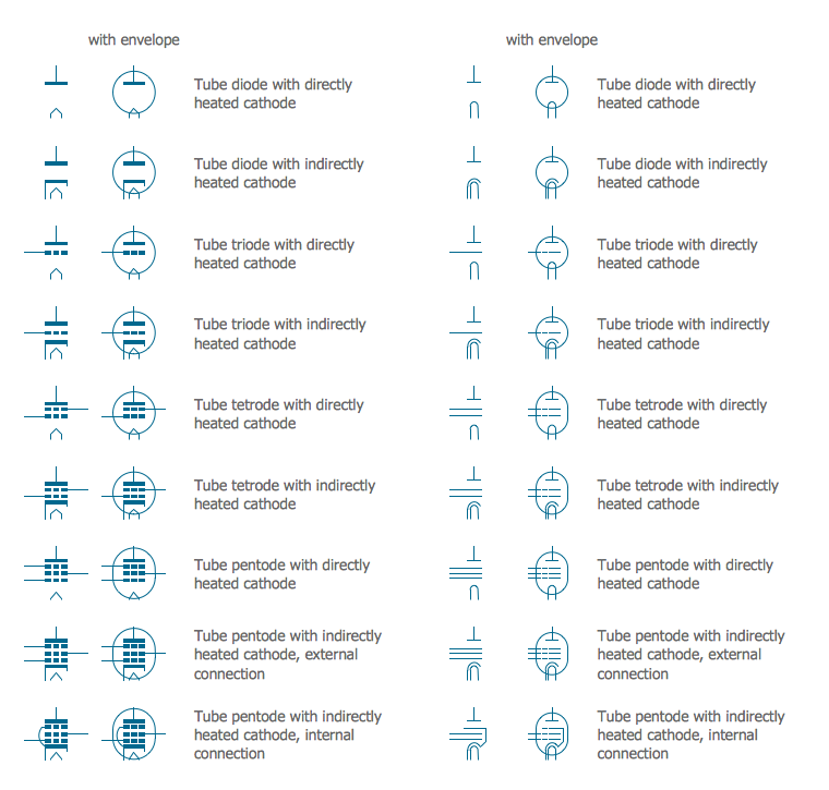
Invented in 1904 by John Ambrose Fleming, vacuum tubes were a basic component for electronics throughout the first half of the twentieth century, which saw the diffusion of radio, television, radar, sound reinforcement, sound recording and reproduction, large telephone networks, analog and digital computers, and industrial process control. From the mid-1950s solid-state devices such as transistors gradually replaced tubes. However, there are still a few applications for which tubes are preferred to semiconductors; for example, the magnetron used in microwave ovens, and certain high-frequency amplifiers. 26 libraries of the Electrical Engineering Solution of ConceptDraw DIAGRAM make your electrical diagramming simple, efficient, and effective. You can simply and quickly drop the ready-to-use objects from libraries into your document to create the electrical diagram.Electrical Symbols — Thermo
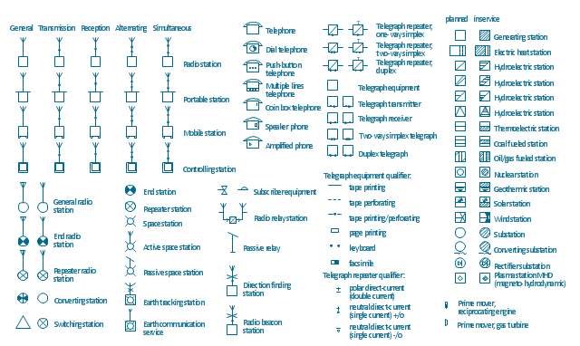
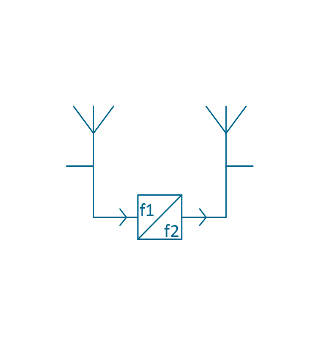
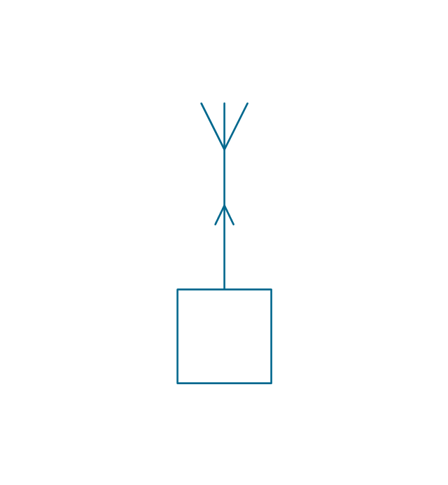
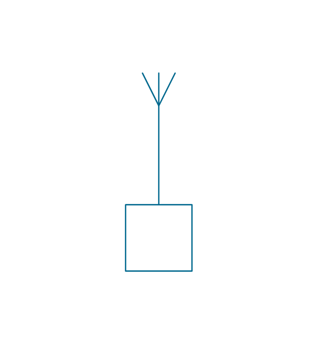
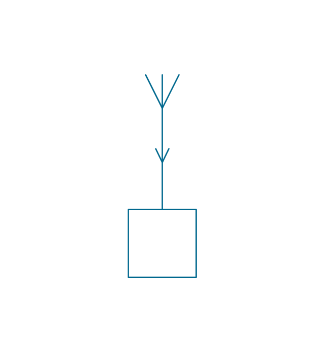
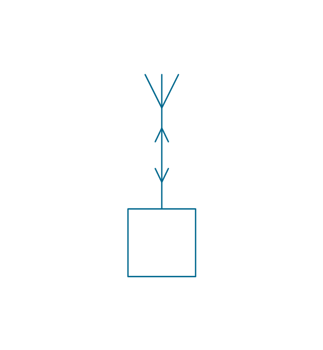
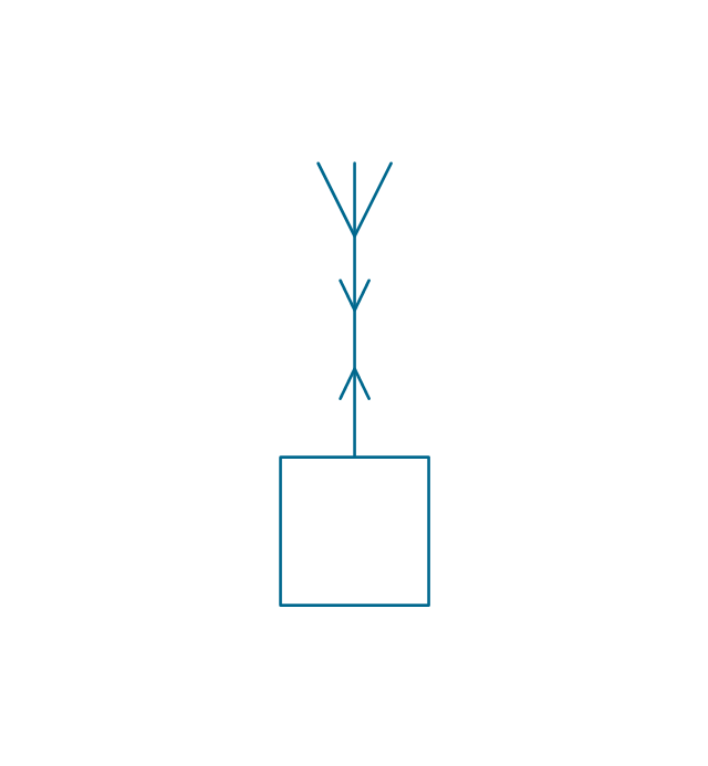
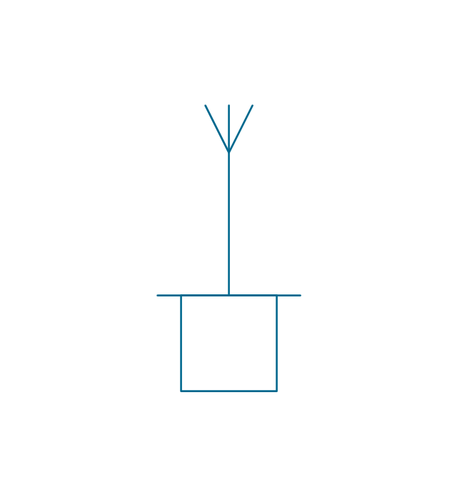
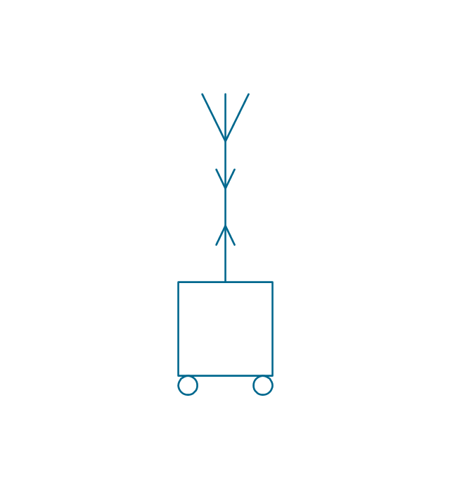
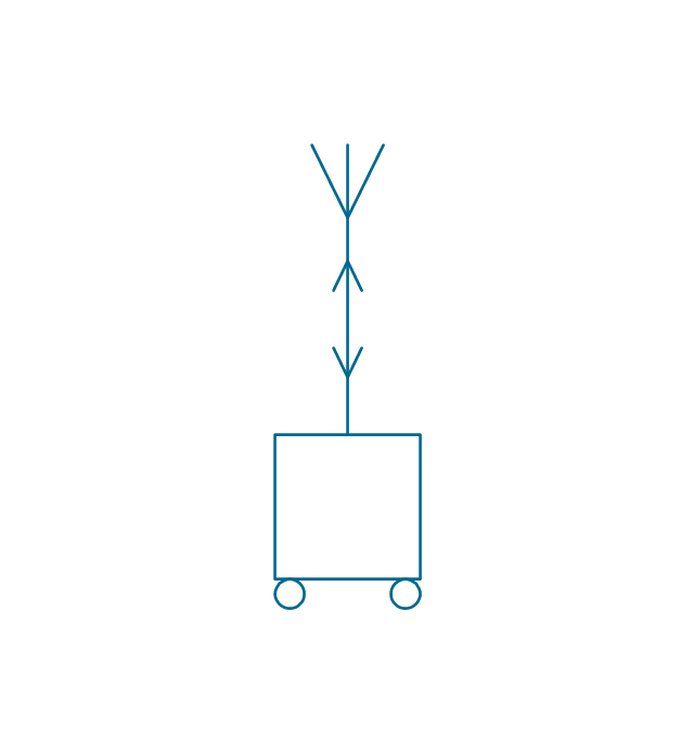
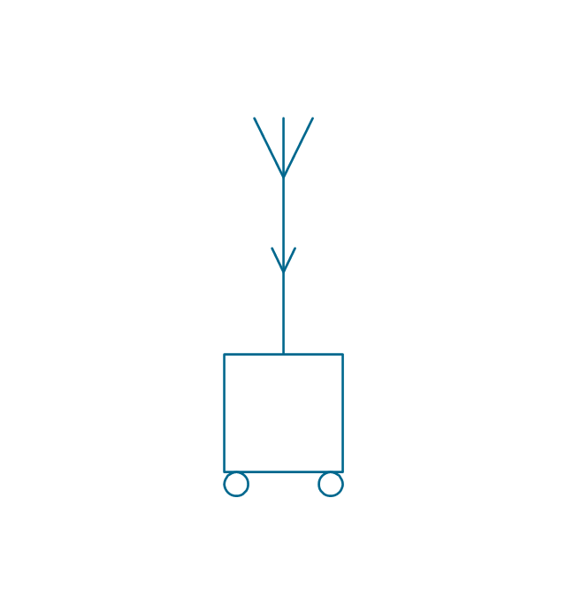
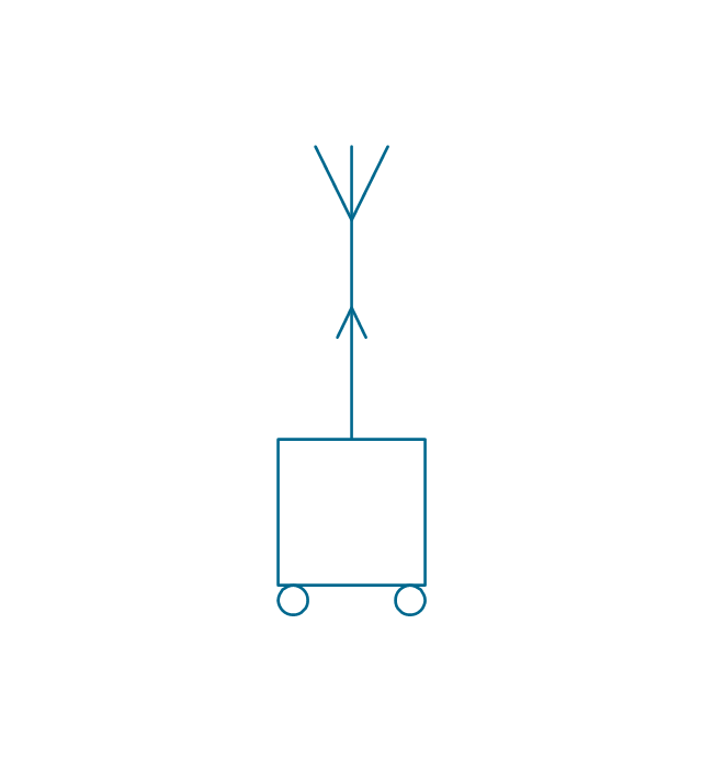
A thermocouple is an electrical device consisting of two different conductors forming electrical junctions at differing temperatures. A thermocouple produces a temperature-dependent voltage as a result of the thermoelectric effect, and this voltage can be interpreted to measure temperature. Thermocouples are a widely used type of temperature sensor. 26 libraries of the Electrical Engineering Solution of ConceptDraw DIAGRAM make your electrical diagramming simple, efficient, and effective. You can simply and quickly drop the ready-to-use objects from libraries into your document to create the electrical diagram.The vector stencils library "Stations" contains 110 symbols of communications equipment, generating, transmitting and receiving stations; substations; satellites; and power plants.
Use these shapes for drawing diagrams of power generation and distribution and radio relay systems in the ConceptDraw PRO diagramming and vector drawing software extended with the Electrical Engineering solution from the Engineering area of ConceptDraw Solution Park.
www.conceptdraw.com/ solution-park/ engineering-electrical
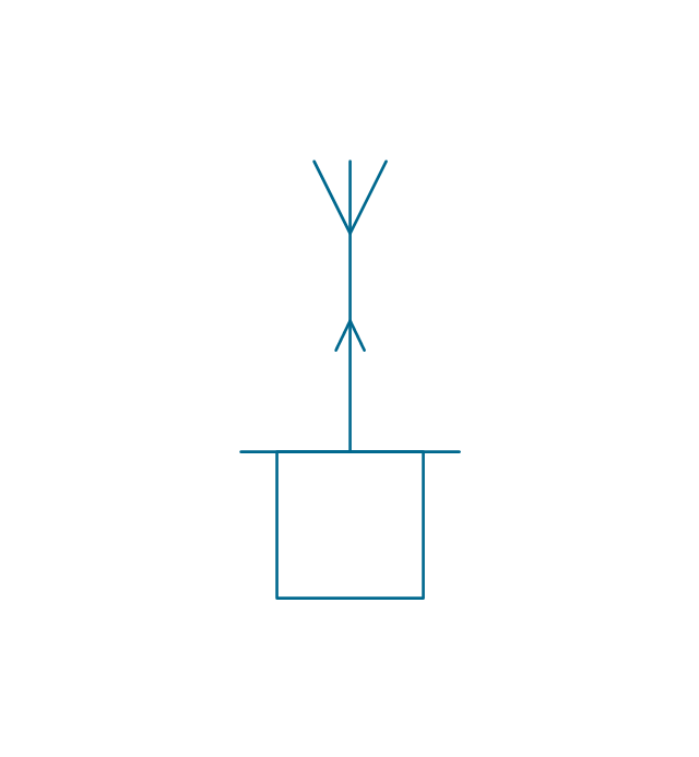
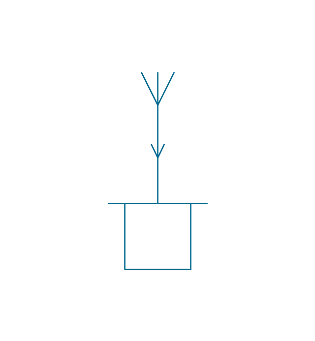
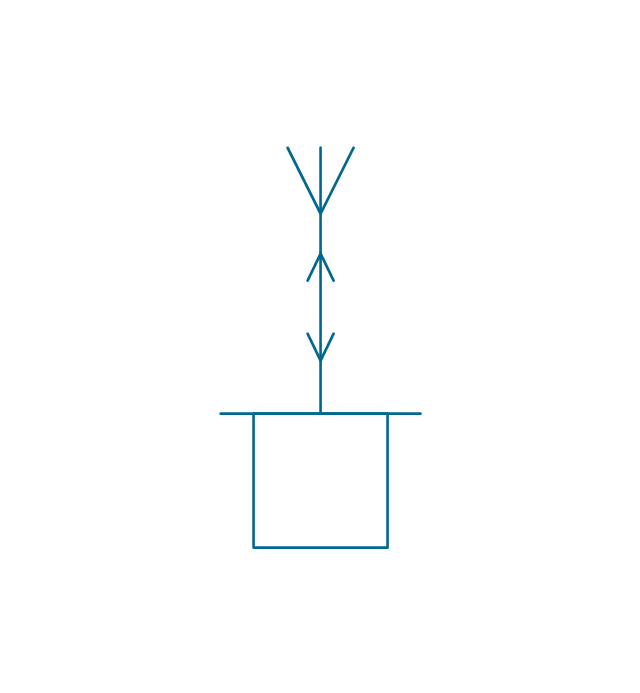
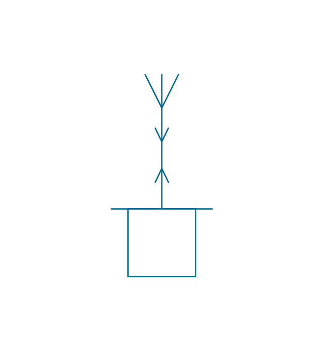
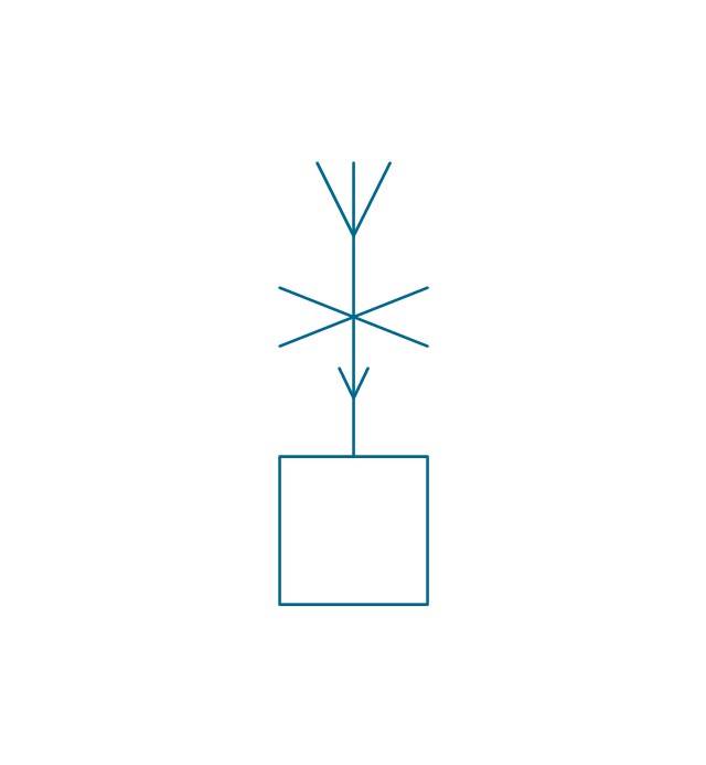
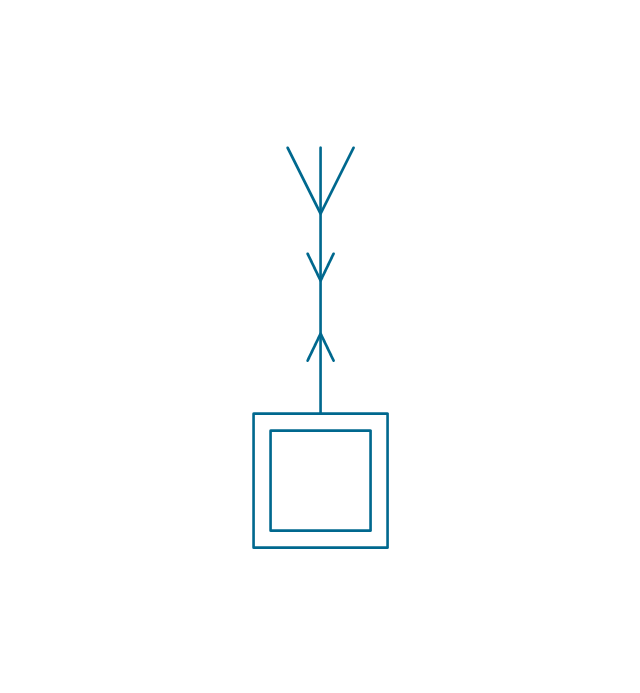
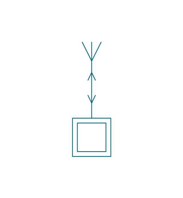
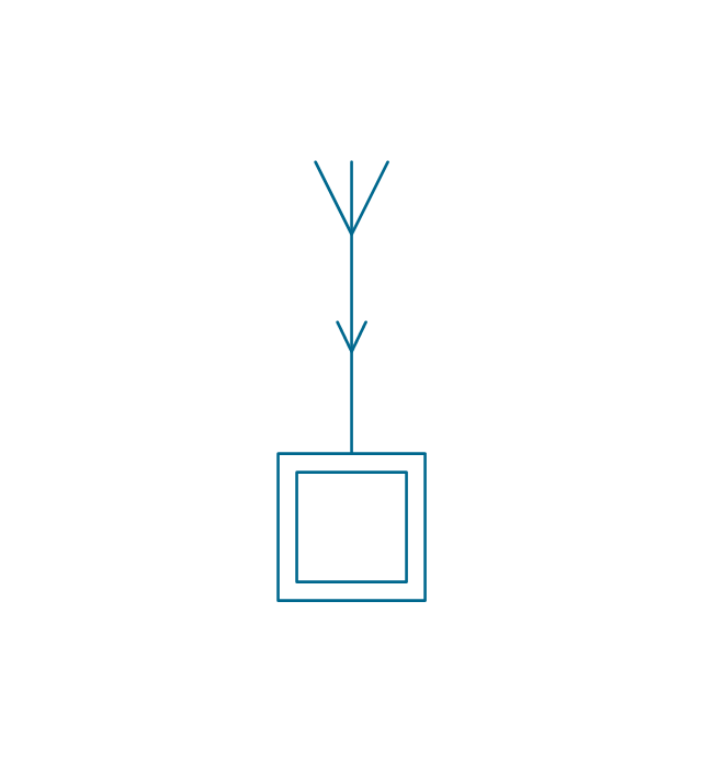
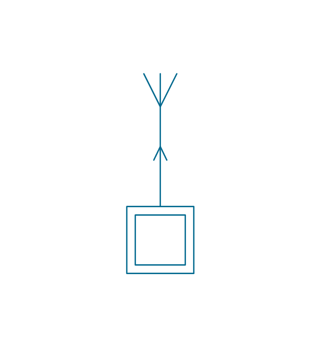
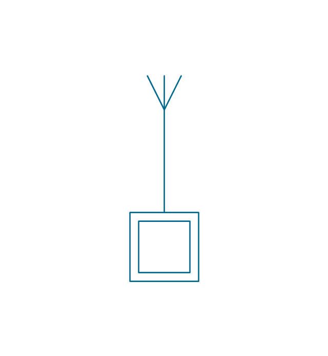
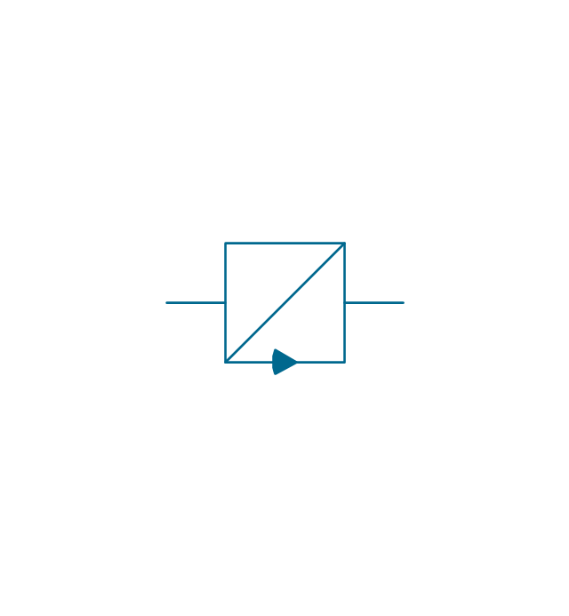
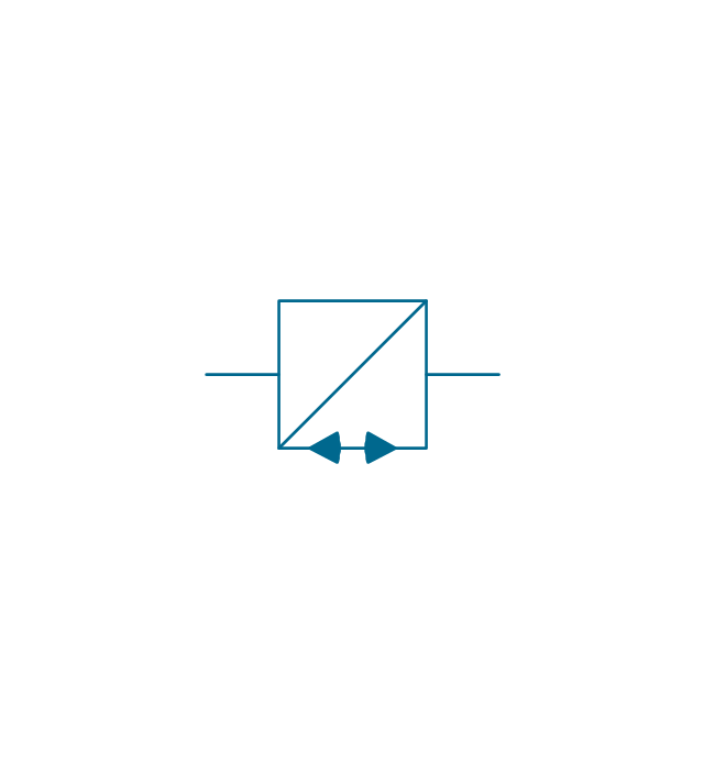
The vector stencils library "Stations" contains 110 symbols of communications equipment, generating, transmitting and receiving stations; substations; satellites; and power plants for power generation and distribution and radio relay systems.
"A power station (also referred to as a generating station, power plant, powerhouse or generating plant) is an industrial facility for the generation of electric power. At the center of nearly all power stations is a generator, a rotating machine that converts mechanical power into electrical power by creating relative motion between a magnetic field and a conductor. The energy source harnessed to turn the generator varies widely. It depends chiefly on which fuels are easily available, cheap enough and on the types of technology that the power company has access to. Most power stations in the world burn fossil fuels such as coal, oil, and natural gas to generate electricity, and some use nuclear power, but there is an increasing use of cleaner renewable sources such as solar, wind, wave and hydroelectric." [Power station. Wikipedia]
"Radio broadcasting is a one-way wireless transmission over radio waves intended to reach a wide audience. Stations can be linked in radio networks to broadcast a common radio format, either in broadcast syndication or simulcast or both. Audio broadcasting also can be done via cable radio, local wire television networks, satellite radio, and internet radio via streaming media on the Internet.
The signal types can be either analog audio or digital audio." [Radio broadcasting. Wikipedia]
The shapes example "Design elements - Stations" was drawn using the ConceptDraw PRO diagramming and vector drawing software extended with the Electrical Engineering solution from the Engineering area of ConceptDraw Solution Park.
 Electrical Engineering
This solution extends ConceptDraw DIAGRAM.9.5 (or later) with electrical engineering samples, electrical schematic symbols, electrical diagram symbols, templates and libraries of design elements, to help you design electrical schematics, digital and analog
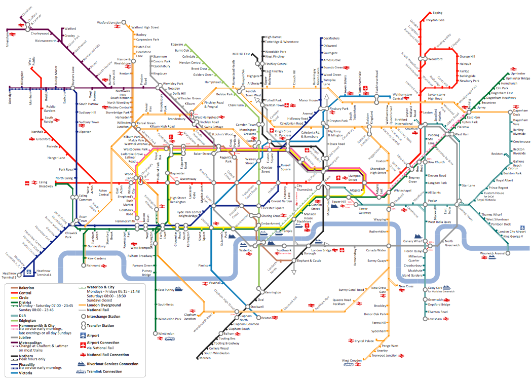
How to draw Metro Map style infographics? (London)
Tool to draw Metro Map styled inforgraphics. London Tube map sample.Mesh Network Topology Diagram
A Mesh Network Topology is a computer network topology built on the principle of cells. The network workstations are the mesh nodes, they are connected to each other, usually to the principle "each with each" (a fully connected network) and interact in the distribution of data in a network. Each node relays the data for the network and can take the role of switch for other participants. Mesh Network Topology is sufficiently complex to configure, but however it provides a high fault tolerance, has a capability for self-healing and is considered as quite reliable. Large number of nodes' connections assures a wide selection of route of following the traffic within a network, therefore the breaking of one connection will not disrupt the functioning of network as a whole. As a rule, the Mesh Networks are wireless. The Mesh Network Topology Diagrams of any complexity and Wireless Mesh Network Diagrams are easy for construction in ConceptDraw DIAGRAM diagramming and vector drawing software using the tools of Computer Network Diagrams solution from Computer and Networks area.What is Gantt Chart (historical reference)
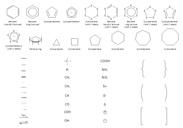
Historical reference about the Gantt chart.The vector stencils library "Chemical drawings" contains 81 symbols of organic compounds and functional groups for chemical drawing.
Use it to draw structural formulas of organic molecules, schemes of chemical reactions and organic chemistry diagrams.
"Structural drawings.
Organic molecules are described more commonly by drawings or structural formulas, combinations of drawings and chemical symbols. The line-angle formula is simple and unambiguous. In this system, the endpoints and intersections of each line represent one carbon, and hydrogen atoms can either be notated explicitly or assumed to be present as implied by tetravalent carbon. The depiction of organic compounds with drawings is greatly simplified by the fact that carbon in almost all organic compounds has four bonds, nitrogen three, oxygen two, and hydrogen one. ...
Organic reactions.
Organic reactions are chemical reactions involving organic compounds. While pure hydrocarbons undergo certain limited classes of reactions, many more reactions which organic compounds undergo are largely determined by functional groups. The general theory of these reactions involves careful analysis of such properties as the electron affinity of key atoms, bond strengths and steric hindrance. These issues can determine the relative stability of short-lived reactive intermediates, which usually directly determine the path of the reaction.
The basic reaction types are: addition reactions, elimination reactions, substitution reactions, pericyclic reactions, rearrangement reactions and redox reactions. ...
Each reaction has a stepwise reaction mechanism that explains how it happens in sequence - although the detailed description of steps is not always clear from a list of reactants alone.
The stepwise course of any given reaction mechanism can be represented using arrow pushing techniques in which curved arrows are used to track the movement of electrons as starting materials transition through intermediates to final products." [Organic chemistry. Wikipedia]
The chemical symbols example "Design elements - Chemical drawings" was created using the ConceptDraw PRO software extended with the Chemistry solution from the Science and Education area of ConceptDraw Solution Park.
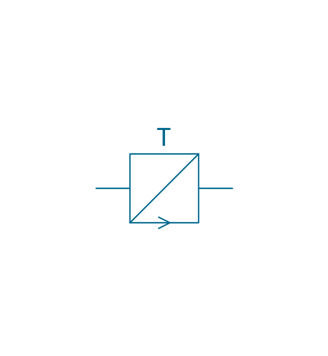
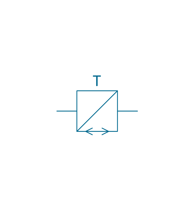
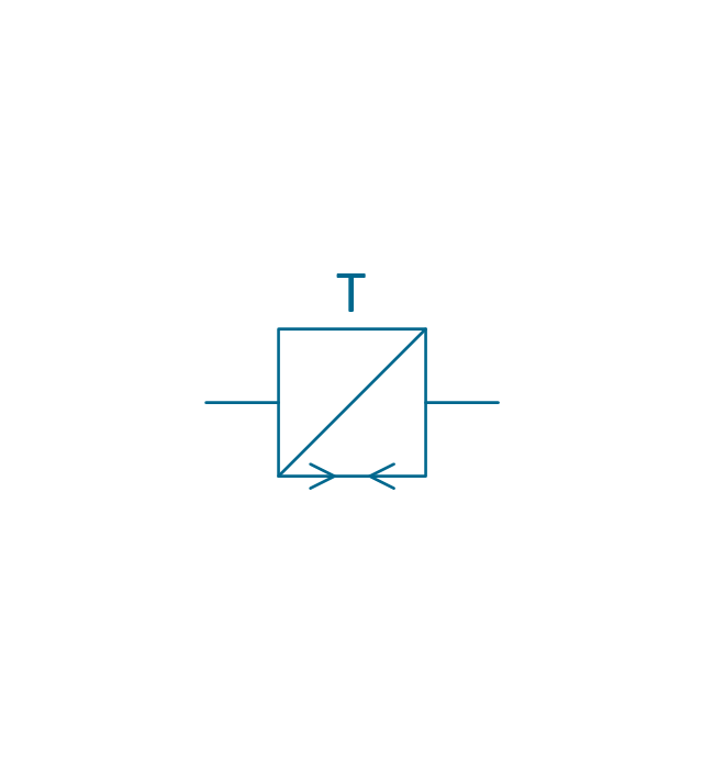
The vector stencils library "Stations" contains 110 symbols of communications equipment, generating, transmitting and receiving stations; substations; satellites; and power plants.
Use these shapes for drawing diagrams of power generation and distribution and radio relay systems in the ConceptDraw PRO diagramming and vector drawing software extended with the Electrical Engineering solution from the Engineering area of ConceptDraw Solution Park.
www.conceptdraw.com/ solution-park/ engineering-electrical
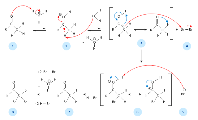
This chemical reaction mechanism drawing depicts steps of carbonyl compound halogenation reaction.
"Alpha-substitution reactions occur at the position next to the carbonyl group, the α-position, and involve the substitution of an α hydrogen atom by an electrophile, E, through either an enol or enolate ion intermediate. ...
Alpha Halogenation of Aldehydes and Ketones.
A particularly common α-substitution reaction in the laboratory is the halogenation of aldehydes and ketones at their α positions by reaction Cl2, Br2 or I2 in acidic solution. Bromine in acetic acid solvent is often used. ...
The halogenation is a typical α-substitution reaction that proceeds by acid catalyzed formation of an enol intermediate." [Carbonyl Alpha-Substitution Reactions. Wikipedia]
This example was redesigned from the Wikimedia Commons file: Halogenierung Mechanismus Version 3-Seite001.svg. [commons.wikimedia.org/ wiki/ File:Halogenierung_ Mechanismus_ Version_ 3-Seite001.svg]
This image is available under the Creative Commons Attribution-ShareAlike 3.0 Unported License. [creativecommons.org/ licenses/ by-sa/ 3.0/ ]
The chemical drawing example "Carbonyl compound halogenation mechanism" was created using the ConceptDraw PRO diagramming and vector drawing software extended with the Chemistry solution from the Science and Education area of ConceptDraw Solution Park.
- Electrical Symbols , Electrical Diagram Symbols | Electrical Symbols ...
- Electrical Symbols , Electrical Diagram Symbols | Electrical Symbols ...
- Symbols Of Substation Equipments In Visio
- Electrical Symbols , Electrical Diagram Symbols | Electrical Symbols ...
- Electrical Drawing Software and Electrical Symbols | Electrical ...
- Design elements - Stations | Substation Equipment List And Symbol
- Electrical Symbols , Electrical Diagram Symbols | Electrical Symbols ...
- Electrical Symbols , Electrical Diagram Symbols | Electrical Drawing ...
- Electrical Symbols , Electrical Diagram Symbols | Electrical Symbols ...
- Symbol For Electrical Equipment
- Electrical Sub Station Symbol Floorplan
- Symbol For Equipment In Sub Station
- Electrical Symbols — Stations | Power Substation Symbol
- Electrical Symbols , Electrical Diagram Symbols | Electrical Symbols ...
- Electrical Symbols , Electrical Diagram Symbols | Electrical Symbols ...
- Symbols Of Electrical Equipments
- The Circuit Symbols For Power Generation Equipment
- Electrical Symbols — Switches and Relays | How To use House ...
- Electrical Symbols , Electrical Diagram Symbols | Substation ...
- How To use Switches in Network Diagram | Substation Use Symbols









-stations---vector-stencils-library.png--diagram-flowchart-example.png)
-+/o-stations---vector-stencils-library.png--diagram-flowchart-example.png)
--/o-stations---vector-stencils-library.png--diagram-flowchart-example.png)


-stations---vector-stencils-library.png--diagram-flowchart-example.png)
-stations---vector-stencils-library.png--diagram-flowchart-example.png)
-stations---vector-stencils-library.png--diagram-flowchart-example.png)
-stations---vector-stencils-library.png--diagram-flowchart-example.png)
-stations---vector-stencils-library.png--diagram-flowchart-example.png)
-stations---vector-stencils-library.png--diagram-flowchart-example.png)
-2-stations---vector-stencils-library.png--diagram-flowchart-example.png)
-2-stations---vector-stencils-library.png--diagram-flowchart-example.png)
-3-stations---vector-stencils-library.png--diagram-flowchart-example.png)
-3-stations---vector-stencils-library.png--diagram-flowchart-example.png)
-4-stations---vector-stencils-library.png--diagram-flowchart-example.png)
-4-stations---vector-stencils-library.png--diagram-flowchart-example.png)
-stations---vector-stencils-library.png--diagram-flowchart-example.png)
-stations---vector-stencils-library.png--diagram-flowchart-example.png)
-stations---vector-stencils-library.png--diagram-flowchart-example.png)
-stations---vector-stencils-library.png--diagram-flowchart-example.png)
-stations---vector-stencils-library.png--diagram-flowchart-example.png)
-stations---vector-stencils-library.png--diagram-flowchart-example.png)
-stations---vector-stencils-library.png--diagram-flowchart-example.png)
-stations---vector-stencils-library.png--diagram-flowchart-example.png)
-stations---vector-stencils-library.png--diagram-flowchart-example.png)
-stations---vector-stencils-library.png--diagram-flowchart-example.png)
-stations---vector-stencils-library.png--diagram-flowchart-example.png)
-stations---vector-stencils-library.png--diagram-flowchart-example.png)
-stations---vector-stencils-library.png--diagram-flowchart-example.png)
-stations---vector-stencils-library.png--diagram-flowchart-example.png)
-stations---vector-stencils-library.png--diagram-flowchart-example.png)
-stations---vector-stencils-library.png--diagram-flowchart-example.png)
-stations---vector-stencils-library.png--diagram-flowchart-example.png)
-stations---vector-stencils-library.png--diagram-flowchart-example.png)


-stations---vector-stencils-library.png--diagram-flowchart-example.png)
-stations---vector-stencils-library.png--diagram-flowchart-example.png)
-stations---vector-stencils-library.png--diagram-flowchart-example.png)
-stations---vector-stencils-library.png--diagram-flowchart-example.png)
