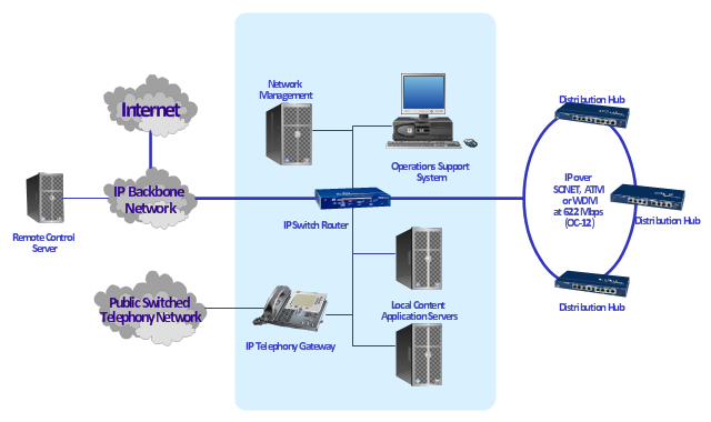
"A cable television headend is a master facility for receiving television signals for processing and distribution over a CATV system. The headend facility is normally unstaffed and surrounded by some type of security fencing and is typically a building or large shed housing electronic equipment used to receive and re-transmit video over the local cable infrastructure. One can also find head ends in power line communication (PLC) substations and Internet communications networks." [Cable television headend. Wikipedia]
This regional cable head-end diagram example was created using the ConceptDraw PRO diagramming and vector drawing software extended with the Computer and Networks solution from the Computer and Networks area of ConceptDraw Solution Park.
This regional cable head-end diagram example was created using the ConceptDraw PRO diagramming and vector drawing software extended with the Computer and Networks solution from the Computer and Networks area of ConceptDraw Solution Park.
Basic Flowchart Symbols and Meaning
Flowcharts are the best for visually representation the business processes and the flow of a custom-order process through various departments within an organization. ConceptDraw PRO diagramming and vector drawing software extended with Flowcharts solution offers the full set of predesigned basic flowchart symbols which are gathered at two libraries: Flowchart and Flowcharts Rapid Draw. Among them are: process, terminator, decision, data, document, display, manual loop, and many other specific symbols. The meaning for each symbol offered by ConceptDraw gives the presentation about their proposed use in professional Flowcharts for business and technical processes, software algorithms, well-developed structures of web sites, Workflow diagrams, Process flow diagram and correlation in developing on-line instructional projects or business process system. Use of ready flow chart symbols in diagrams is incredibly useful - you need simply drag desired from the libraries to your document and arrange them in required order. There are a few serious alternatives to Visio for Mac, one of them is ConceptDraw PRO. It is one of the main contender with the most similar features and capabilities.
The vector stencils library "Cabinets and bookcases" contains 41 vector shapes for drawing floor plans.
"A cabinet is a box-shaped piece of furniture with doors or drawers for storing miscellaneous items. Some cabinets stand alone while others are built into a wall or are attached to it... Cabinets are typically made of wood or, now increasingly, of synthetic materials. Commercial grade cabinets, which differ in the materials used, are called casework.
Cabinets usually have one or more doors on the front, which are mounted with door hardware, and occasionally a lock. Many cabinets have doors and drawers or only drawers. Short cabinets often have a finished surface on top that can be used for display, or as a working surface" [Cabinetry. Wikipedia]
Use the design elements library "Cabinets and bookcases" to draw the office furniture and equipment layout plans using the ConceptDraw PRO diagramming and vector drawing software. The shapes library "Cabinets and bookcases" is included in the Office Layout Plans solution from Building Plans area of ConceptDraw Solution Park.
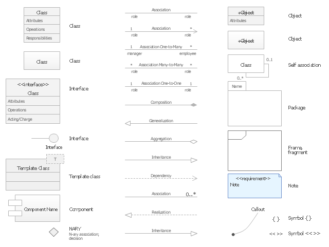
The vector stencils library "UML class diagrams" contains 38 symbols for the ConceptDraw PRO diagramming and vector drawing software.
"... classes are represented with boxes which contain three parts:
(1) The top part contains the name of the class. It is printed in Bold, centered and the first letter capitalized.
(2) The middle part contains the attributes of the class. They are left aligned and the first letter is lower case.
(3) The bottom part gives the methods or operations the class can take or undertake. They are also left aligned and the first letter is lower case. ...
To indicate a classifier scope for a member, its name must be underlined. ...
An association can be named, and the ends of an association can be adorned with role names, ownership indicators, multiplicity, visibility, and other properties. ...
Aggregation ... is graphically represented as a hollow diamond shape on the containing class end of the tree with a single line that connects the contained class to the containing class.
... graphical representation of a composition relationship is a filled diamond shape on the containing class end of the tree of lines that connect contained class(es) to the containing class.
... graphical representation of a Generalization is a hollow triangle shape on the superclass end of the line (or tree of lines) that connects it to one or more subtypes.
... graphical representation of a Realization is a hollow triangle shape on the interface end of the dashed line (or tree of lines) that connects it to one or more implementers. A plain arrow head is used on the interface end of the dashed line that connects it to its users.
Multiplicity ... representation of an association is a line with an optional arrowhead indicating the role of the object(s) in the relationship, and an optional notation at each end indicating the multiplicity of instances of that entity (the number of objects that participate in the association).
Entity classes ... are drawn as circles with a short line attached to the bottom of the circle. Alternatively, they can be drawn as normal classes with the «entity» stereotype notation above the class name." [Class diagram. Wikipedia]
The example "Design elements - UML class diagrams" is included in the Rapid UML solution from the Software Development area of ConceptDraw Solution Park.
"A football pitch (also known as a football field or soccer field) is the playing surface for the game of football made of turf. Its dimensions and markings are defined by Law 1 of the Laws of the Game, "The Field of Play".
All line markings on the pitch form part of the area which they define. For example, a ball on or above the touchline is still on the field of play; a ball on the line of the goal area is in the goal area; and a foul committed over the 16.5-metre (18-yard) line has occurred in the penalty area. Therefore a ball must completely cross the touchline to be out of play, and a ball must wholly cross the goal line (between the goal posts) before a goal is scored; if any part of the ball is still on or above the line, the ball is still in play.
The field descriptions that apply to adult matches are described below. Note that due to the original formulation of the Laws in England and the early supremacy of the four British football associations within IFAB, the standard dimensions of a football pitch were originally expressed in imperial units. The Laws now express dimensions with approximate metric equivalents (followed by traditional units in brackets), but use of the imperial units remains common in some countries, especially in the United Kingdom." [Association football pitch. Wikipedia]
The template "End zone view association football pitch" for the ConceptDraw PRO diagramming and vector drawing software is included in the Soccer solution from the Sport area of ConceptDraw Solution Park.
www.conceptdraw.com/ solution-park/ sport-soccer
The vector stencils library "American football positions" contains 38 american football (gridiron) players symbols.
Use it for drawing diagrams of American football positions in the ConceptDraw PRO diagramming and vector drawing software extended with the Football solution from the Sport area of ConceptDraw Solution Park.
Use it for drawing diagrams of American football positions in the ConceptDraw PRO diagramming and vector drawing software extended with the Football solution from the Sport area of ConceptDraw Solution Park.
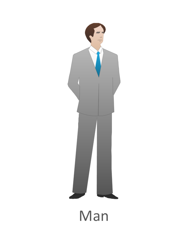
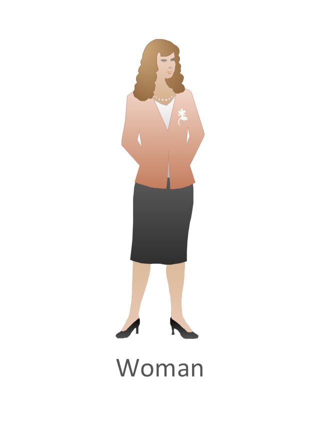
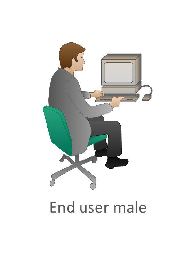
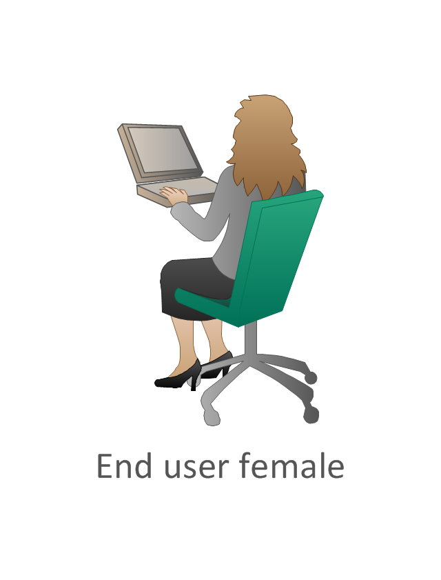
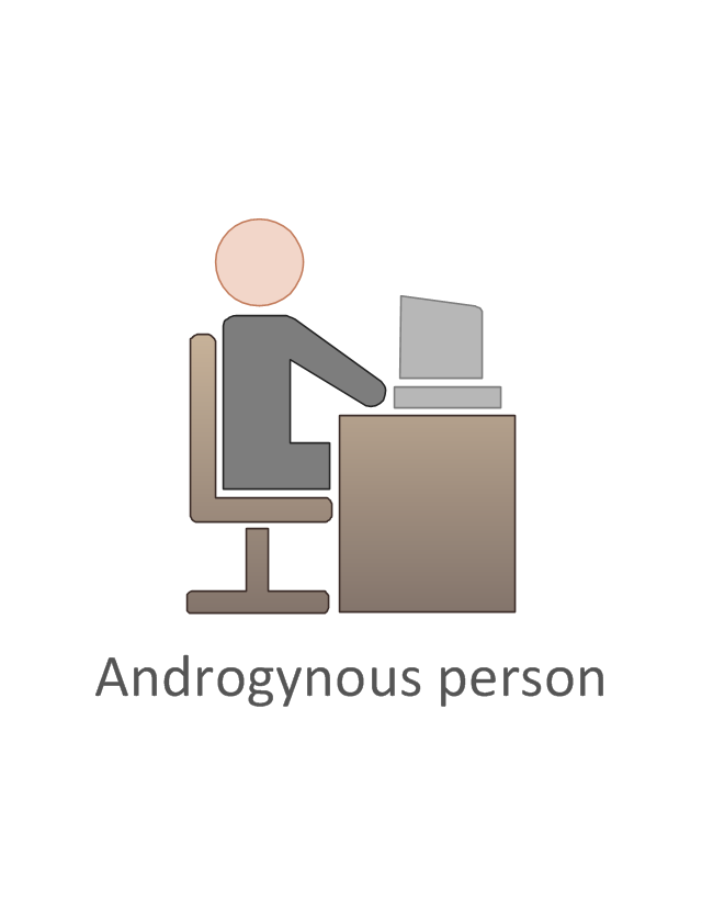
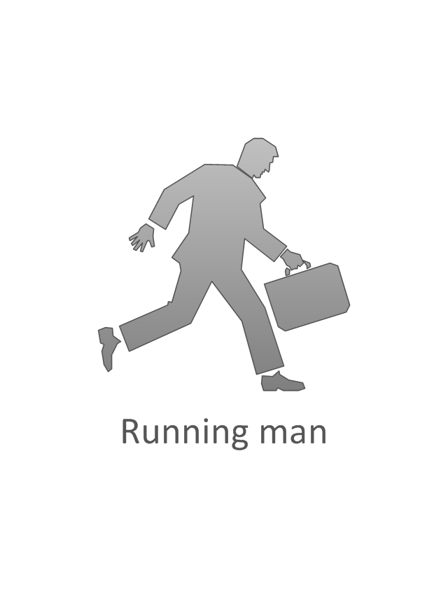
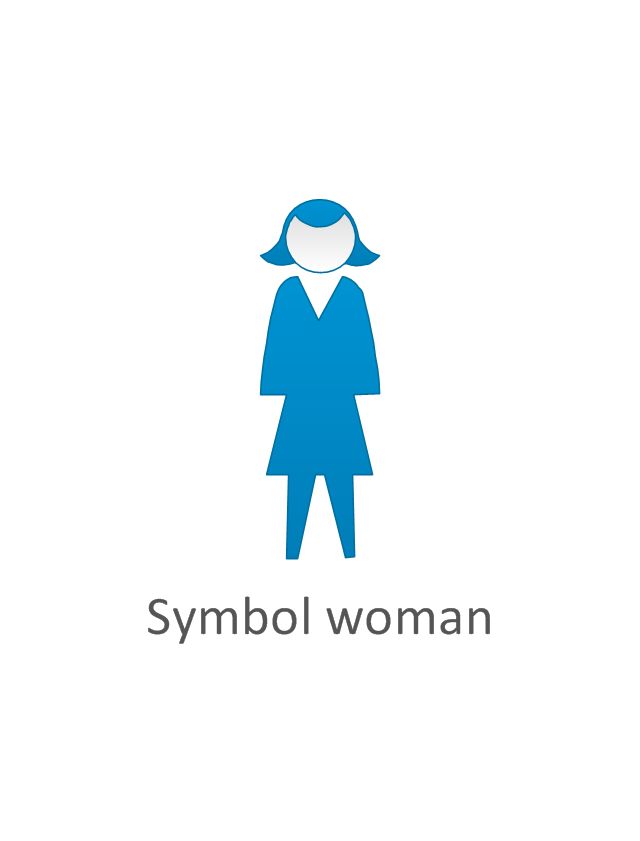
The vector stencils library "Cisco people" contains 17 pictogram symbols and clipart icons of people for drawing Cisco computer network diagrams.
The symbols example "Cisco people - Vector stencils library" was created using the ConceptDraw PRO diagramming and vector drawing software extended with the Cisco Network Diagrams solution from the Computer and Networks area of ConceptDraw Solution Park.
www.conceptdraw.com/ solution-park/ computer-networks-cisco
This vector stencils library contains 23 events symbols for drawing business process diagrams (BPMN 1.2).
An Event is something that happens during the course of a business process. These events affect the flow of the process and usually have a cause or an impact. There are three types of Events, based on when they affect the flow: Start, Intermediate and End.
An Event is something that happens during the course of a business process. These events affect the flow of the process and usually have a cause or an impact. There are three types of Events, based on when they affect the flow: Start, Intermediate and End.
The vector stencils library "HVAC ductwork" contains 55 duct and vent symbols of HVAC mechanical components. Use it for drawing HVAC ductwork system diagrams, heating, ventilation, air conditioning, refrigeration, automated building control, and environmental control design in the ConceptDraw PRO diagramming and vector drawing software extended with the HVAC Plans solution from the Building Plans area of ConceptDraw Solution Park.
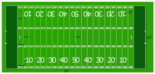
"Football games are played on a rectangular field that measures 120 yards (110 m) long and 53.33 yards (48.76 m) wide. Lines marked along the ends and sides of the field are known respectively as the end lines and side lines, and goal lines are marked 9 yards (8.2 m) outward from each end line. Weighted pylons are placed on the inside corner of the intersections of the goal lines and end lines.
White markings on the field identify the distance from the end zone. Inbound lines, or hash marks, are short parallel lines that mark off 1 yard (0.91 m) increments. Yard lines, which run the width of the field, are marked every 5 yards (4.6 m). A line one yard wide is placed at each end of the field. This line is marked at the center of the two-yard line in professional play and at the three-yard line in college play. Numerals that display the yard lines in multiples of ten are placed along both sides of the field.
Goalposts are at the center of the plane of each of the two end lines. The crossbar of these posts is ten feet (3 meters) above the ground, with vertical uprights at the end of the crossbar 18 feet 6 inches (6 m) apart for professional and collegiate play and 23 feet 4 inches (7 m) apart for high school play. The uprights extend vertically 10 yards on professional fields, a minimum of 10 yards on college fields, and a minimum of ten feet on high school fields. Goal posts are padded at the base, and orange ribbons are normally placed at the tip of each upright." [American football. Wikipedia]
The diagram example "Horizontal colored football field" was created using the ConceptDraw PRO diagramming and vector drawing software extended with the Football solution from the Sport area of ConceptDraw Solution Park.
The vector stencils library "Cisco people" contains 17 pictogram symbols and clipart icons of people for drawing Cisco computer network diagrams.
The symbols example "Cisco people - Vector stencils library" was created using the ConceptDraw PRO diagramming and vector drawing software extended with the Cisco Network Diagrams solution from the Computer and Networks area of ConceptDraw Solution Park.
www.conceptdraw.com/ solution-park/ computer-networks-cisco
The symbols example "Cisco people - Vector stencils library" was created using the ConceptDraw PRO diagramming and vector drawing software extended with the Cisco Network Diagrams solution from the Computer and Networks area of ConceptDraw Solution Park.
www.conceptdraw.com/ solution-park/ computer-networks-cisco
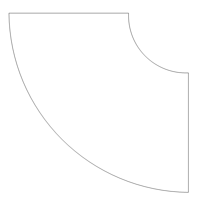
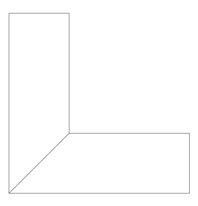
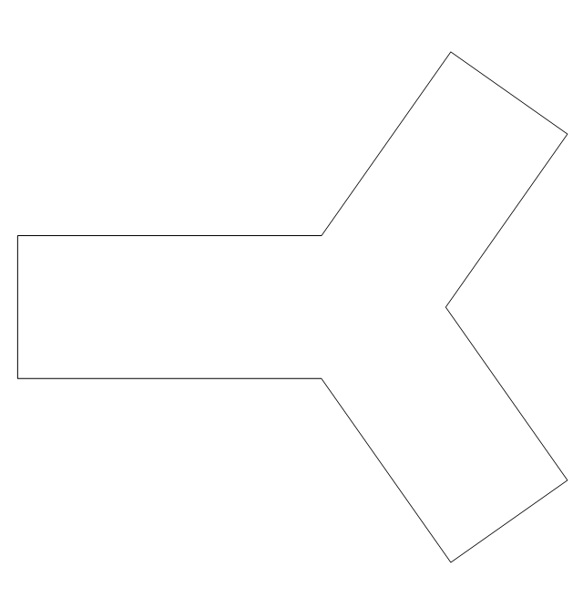
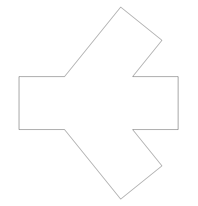
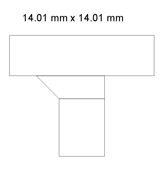
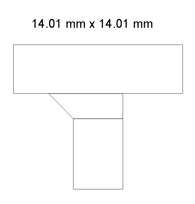
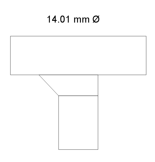
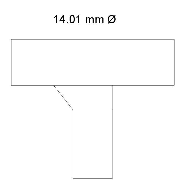
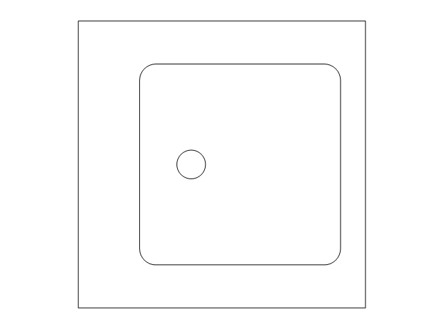
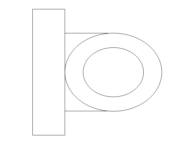
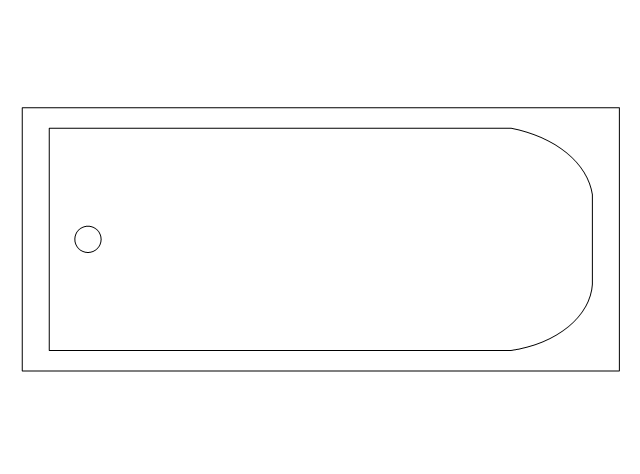
The vector stencils library "Plumbing" contains 31 symbols of plumbing components and bathroom fixtures. Use it for dawing plumbing and piping plans, schematic diagrams, blueprints of waste water disposal systems, hot and cold water supply systems in the ConceptDraw PRO diagramming and vector drawing software extended with the Plumbing and Piping Plans solution from the Building Plans area of ConceptDraw Solution Park.
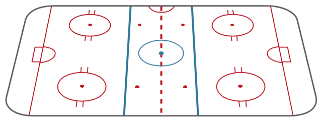
"Markings.
Lines.
The centre line divides the ice in half crosswise. It is used to judge icing, meaning that if a team sends the puck across the centre line (red line), blue line and then across the goal line (that is to say, shoots or dumps the puck past the goal line from behind their own side of the centre line) it is said to be icing. ...
Faceoff spots and circles.
There are 9 faceoff spots on a hockey rink. Most faceoffs take place at these spots. There are two spots in each end zone, two at each end of the neutral zone, and one in the centre of the rink.
There are faceoff circles around the centre ice and end zone faceoff spots. There are hash marks painted on the ice near the end zone faceoff spots. The circles and hash marks show where players may legally position themselves during a faceoff or in game play. ...
Spot and circle dimensions.
Both the center faceoff spot and center faceoff circle are blue. The spot is a solid blue circle 12 inches (30 cm) in diameter. Within the spot is a center, a circle 30 feet (9.1 m) in diameter, painted with a blue line 2 inches (5.1 cm) in width.
All of the other faceoff spots have outlines 2 inches (5.1 cm) thick, forming a circle 2 feet (0.61 m) in diameter measured from the outsides of the outlines, and are filled in with red in all areas except for the 3 inches (7.6 cm) space from the tops and bottoms of the circles, measured from the insides of the outline. ...
Goal posts and nets.
At each end of the ice, there is a goal consisting of a metal goal frame and cloth net in which each team must place the puck to earn points. According to NHL and IIHF rules, the entire puck must cross the entire goal line in order to be counted as a goal. ...
Goal area.
The crease is a special area of the ice designed to allow the goaltender to perform without interference. In most leagues, goals are disallowed if an attacking player enters the goal crease with a stick, skate, or any body part before the puck. For the purposes of this rule, the crease extends vertically from the painted lines to the top of the goal frame. ...
Goaltender trapezoid.
During the 2004-05 American Hockey League (AHL) season, an experimental rule was implemented for the first seven weeks of the season, instituting a goaltender trap zone, more commonly called the trapezoid in reference to its shape. Under the rule, it is prohibited for the goaltender to handle the puck anywhere behind the goal line that is not within the trapezoidal area. If they do so they are assessed a minor penalty for delay of game. ...
Referee's crease.
The referee's crease is a semicircle ten feet in radius in front of the scorekeepers bench." [Ice hockey rink. Wikipedia]
The diagram template "Ice hockey rink view from long side" for the ConceptDraw PRO diagramming and vector drawing software is included in the Hockey solution from the Sport area of ConceptDraw Solution Park.
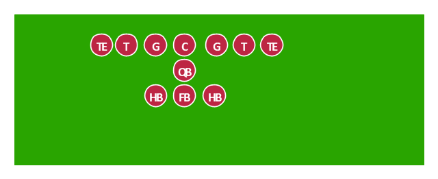
"In American football, a T formation (frequently called the full house formation in modern usage) is a formation used by the offensive team in which three running backs line up in a row about five yards behind the quarterback, forming the shape of a "T".
Numerous variations of the T formation have been developed, including the Power-T, where two tight ends are used, the Pro T, which uses one tight end and one wide receiver, or the Wing T, where one of the running backs (or wingback) lines up one step behind and to the side of the tight end. Any of these can be run using the original spacing, which produced a front of about seven yards, or the Split-T spacing, where the linemen were farther apart and the total length of the line was from 10-16 yards." [T formation. Wikipedia]
The American football positions diagram example "Offensive formation - T-formation" was created using the ConceptDraw PRO diagramming and vector drawing software extended with the Football solution from the Sport area of ConceptDraw Solution Park.
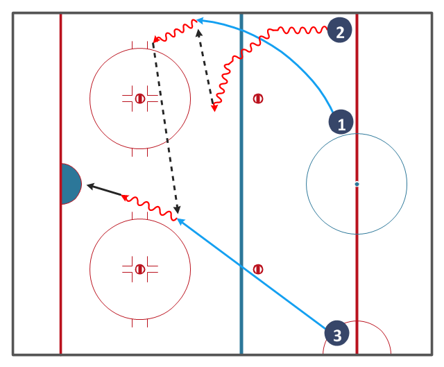
"The blue lines divide the rink into three zones. The central zone is called the neutral zone or simply centre ice. The generic term for the outer zones is end zones, but they are more commonly referred to by terms relative to each team. The end zone in which a team is trying to score is called the attacking zone or offensive zone; the end zone in which the team's own goal net is located is called the defending zone or defensive zone.
The blue line is considered part of whichever zone the puck is in. Therefore, if the puck is in the neutral zone, the blue line is part of the neutral zone. It must completely cross the blue line to be considered in the end zone. Once the puck is in the end zone, the blue line becomes part of that end zone. The puck must now completely cross the blue line in the other direction to be considered in the neutral zone again." [Ice hockey rink. Wikipedia]
The hockey drill diagram example "Entering offensive zone" was created using the ConceptDraw PRO diagramming and vector drawing software extended with the Hockey solution from the Sport area of ConceptDraw Solution Park.
- Regional cable head- end diagram
- End zone view association football pitch - Template | Design a ...
- End To End Flow Diagram
- Flowchart End Process Symbol
- Colored Female End User Clipart
- Regional cable head- end diagram | Draw Diagram Software ...
- End zone view association football pitch - Template | Plumbing ...
- End Symbol For Visio
- Regional cable head- end diagram | Draw Diagram Software | Basic ...
- End Line Png
- Regional cable head- end diagram | Local area network (LAN ...
- Regional cable head- end diagram | Basic Network Diagram | Draw ...
- Regional cable head- end diagram | Bus Network Diagram Plc
- Regional cable head- end diagram | Basic Network Diagram ...
- Types of Flowcharts | End Of Process In Bpm Symbol
- End User Icon Png
- Regional cable head- end diagram | Mobile satellite TV network ...
- Flowchart End
- Road signs - Vector stencils library | End Of Priority Road End Of ...
- End To End Process Procurement



-american-football-positions---vector-stencils-library.png--diagram-flowchart-example.png)
-american-football-positions---vector-stencils-library.png--diagram-flowchart-example.png)
-american-football-positions---vector-stencils-library.png--diagram-flowchart-example.png)
-american-football-positions---vector-stencils-library.png--diagram-flowchart-example.png)
-american-football-positions---vector-stencils-library.png--diagram-flowchart-example.png)
-american-football-positions---vector-stencils-library.png--diagram-flowchart-example.png)
-american-football-positions---vector-stencils-library.png--diagram-flowchart-example.png)
-american-football-positions---vector-stencils-library.png--diagram-flowchart-example.png)
-american-football-positions---vector-stencils-library.png--diagram-flowchart-example.png)
-american-football-positions---vector-stencils-library.png--diagram-flowchart-example.png)
-american-football-positions---vector-stencils-library.png--diagram-flowchart-example.png)
-american-football-positions---vector-stencils-library.png--diagram-flowchart-example.png)
-american-football-positions---vector-stencils-library.png--diagram-flowchart-example.png)
-american-football-positions---vector-stencils-library.png--diagram-flowchart-example.png)
-american-football-positions---vector-stencils-library.png--diagram-flowchart-example.png)
-american-football-positions---vector-stencils-library.png--diagram-flowchart-example.png)
-american-football-positions---vector-stencils-library.png--diagram-flowchart-example.png)
-american-football-positions---vector-stencils-library.png--diagram-flowchart-example.png)
-american-football-positions---vector-stencils-library.png--diagram-flowchart-example.png)
-american-football-positions---vector-stencils-library.png--diagram-flowchart-example.png)
-american-football-positions---vector-stencils-library.png--diagram-flowchart-example.png)
-american-football-positions---vector-stencils-library.png--diagram-flowchart-example.png)
-american-football-positions---vector-stencils-library.png--diagram-flowchart-example.png)
-american-football-positions---vector-stencils-library.png--diagram-flowchart-example.png)
-american-football-positions---vector-stencils-library.png--diagram-flowchart-example.png)
-american-football-positions---vector-stencils-library.png--diagram-flowchart-example.png)
-american-football-positions---vector-stencils-library.png--diagram-flowchart-example.png)
-american-football-positions---vector-stencils-library.png--diagram-flowchart-example.png)
-american-football-positions---vector-stencils-library.png--diagram-flowchart-example.png)
-american-football-positions---vector-stencils-library.png--diagram-flowchart-example.png)
-american-football-positions---vector-stencils-library.png--diagram-flowchart-example.png)
-american-football-positions---vector-stencils-library.png--diagram-flowchart-example.png)
-american-football-positions---vector-stencils-library.png--diagram-flowchart-example.png)
-american-football-positions---vector-stencils-library.png--diagram-flowchart-example.png)
-american-football-positions---vector-stencils-library.png--diagram-flowchart-example.png)
-american-football-positions---vector-stencils-library.png--diagram-flowchart-example.png)
-american-football-positions---vector-stencils-library.png--diagram-flowchart-example.png)
-american-football-positions---vector-stencils-library.png--diagram-flowchart-example.png)










































,-sgl-plumbing---vector-stencils-library.png--diagram-flowchart-example.png)
,-dbl-plumbing---vector-stencils-library.png--diagram-flowchart-example.png)
-plumbing---vector-stencils-library.png--diagram-flowchart-example.png)


-plumbing---vector-stencils-library.png--diagram-flowchart-example.png)
-plumbing---vector-stencils-library.png--diagram-flowchart-example.png)
-plumbing---vector-stencils-library.png--diagram-flowchart-example.png)
