 Entity-Relationship Diagram (ERD)
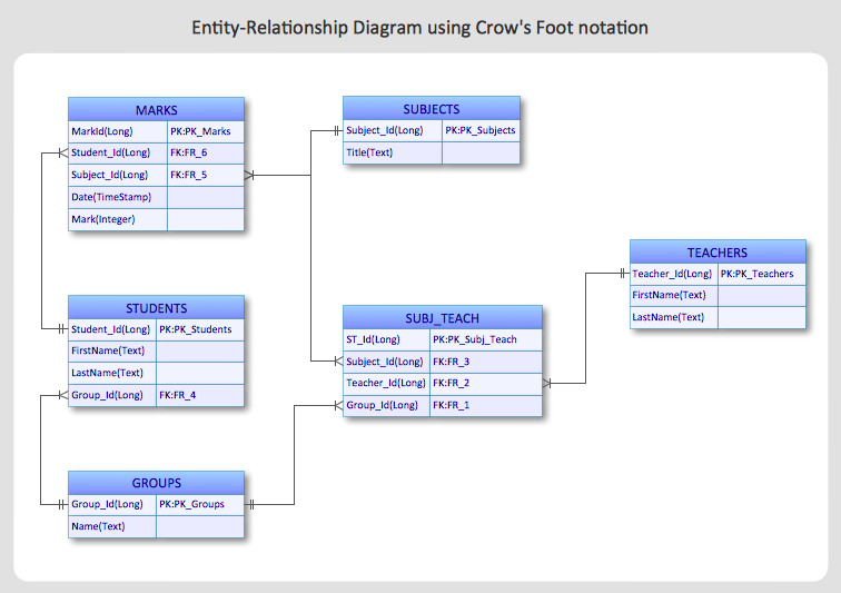
Entity-Relationship Diagram (ERD) solution extends ConceptDraw PRO software with templates, samples and libraries of vector stencils from drawing the ER-diagrams by Chen's and crow’s foot notations.
 Fault Tree Analysis Diagrams
This solution extends ConceptDraw PRO v9.5 or later with templates, fault tree analysis example, samples and a library of vector design elements for drawing FTA diagrams (or negative analytical trees), cause and effect diagrams and fault tree diagrams.
HelpDesk
How to Edit Grouped Shapes in ConceptDraw PRO on OS X
ConceptDraw PRO offers a range of built-in facilities in order to enable you to quickly edit any diagram or other visualization made using ConceptDraw PRO, or MS Visio. Grouping shapes, pictures, or objects lets you style, format, rotate, and move them together, as though they were a single object.HelpDesk
How to Create an Entity-Relationship Diagram Using ConceptDraw Solution Park
An entity-relationship diagram (ERD)is used in a database modeling process. ERD diagram shows a graphical representation of objects or concepts within an information system and their relationships.The ability to describe a database using the Entity-Relationship model is delivered by the ConceptDraw ERD solution.IDEF1X Standard
Use Case Diagrams technology. IDEF1x standard - for work with relational data bases. IDEF1x standard is meant for constructing of conceptual schemes which represent the structure of data in the context of the concerned system, for example, a commercial organization.- Entity-Relationship Diagram (ERD)
- Design elements - ERD (crow's foot notation) | Entity Relationship ...
- Er Diagram Symbols Ppt
- Diagram Images
- Components of ER Diagram | Entity Relationship Diagram Symbols ...
- ERD Symbols and Meanings | Design elements - ER diagram (Chen ...
- Entity Relationship Diagram Symbols and Meaning ERD Symbols ...
- Telecommunication Network Diagrams | Design elements ...
- How to Draw a Good Diagram of a Business Workflow? | Basic ...
- Data Flow Diagram Symbols . DFD Library | Entity Relationship ...
- Images Of Use Case Diagram Of Social Networking Site
- Entity-Relationship Diagram (ERD) | ER Diagrams with ...
- Design elements - ER diagram (Chen notation) | Entity Relationship ...
- Entity Relationship Diagram Symbols and Meaning ERD Symbols ...
- Entity Relationship Diagram Symbols | Design elements - ER ...
- Relationship In Er Diagram Symbols
- Database Flowchart Symbols | Basic Flowchart Symbols and ...
- Entity-Relationship Diagram
- Data Flow Diagrams | Universal Diagramming Area | ER Diagrams ...
- Entity Relationship Diagram Symbols | ERD Symbols and Meanings ...


