Structured Systems Analysis and Design Method. SSADM with ConceptDraw DIAGRAM

DFD Library System

Interface Design

Healthy Foods

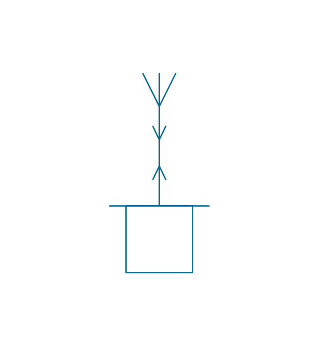
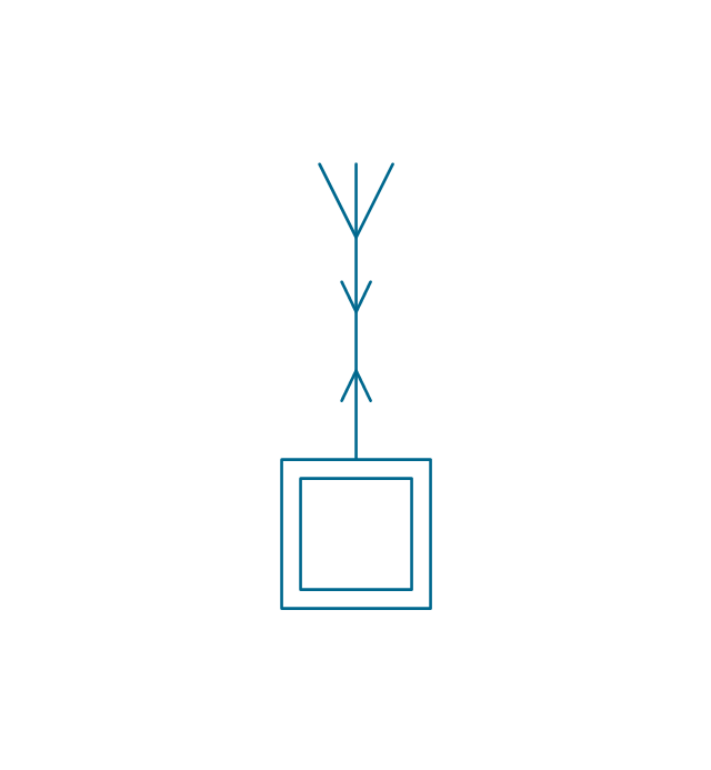
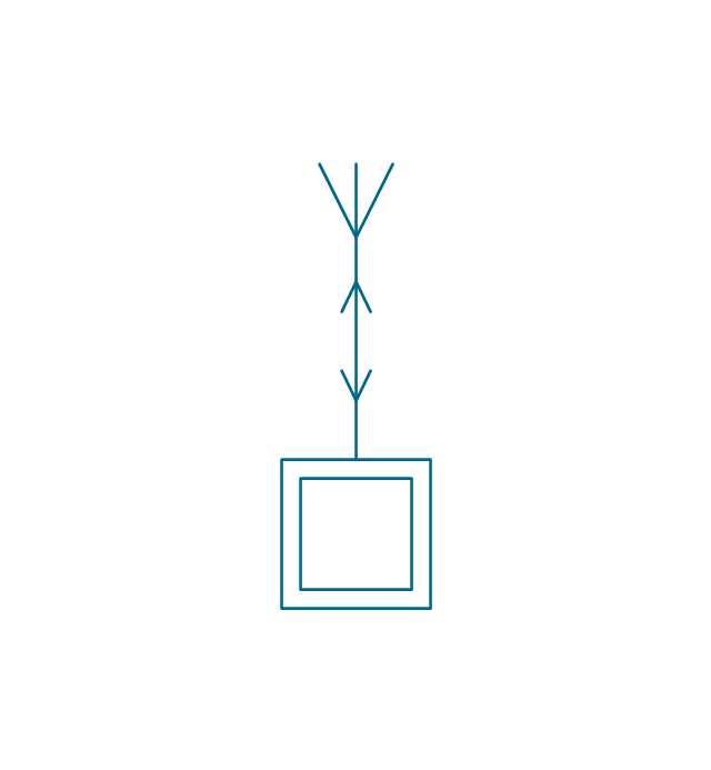
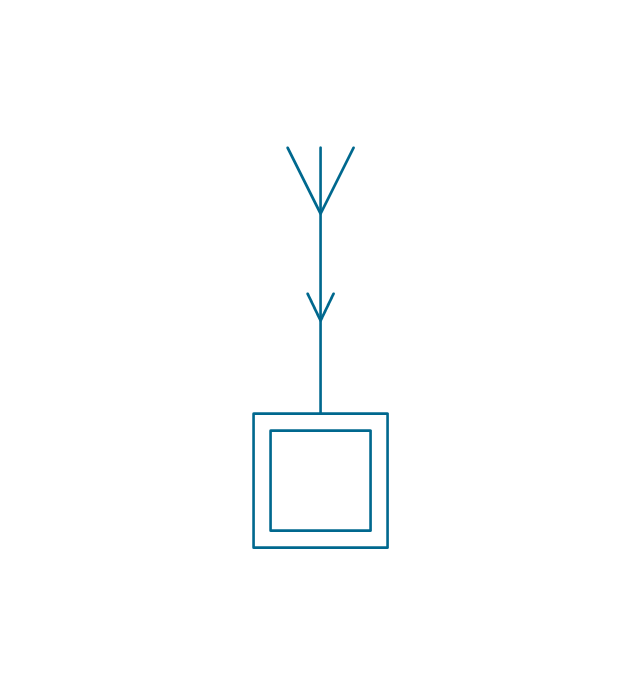
 Jackson Structured Programming (JSP) Diagrams
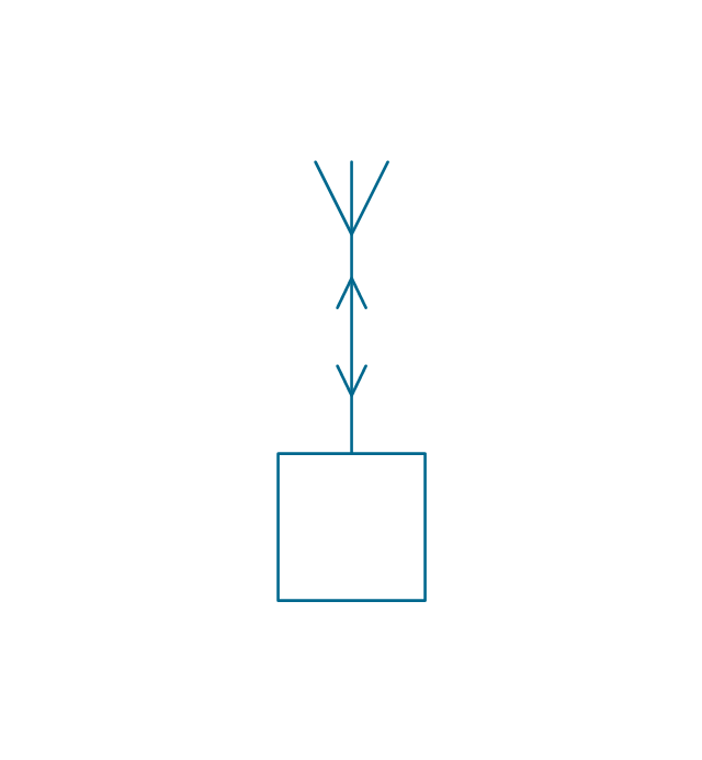
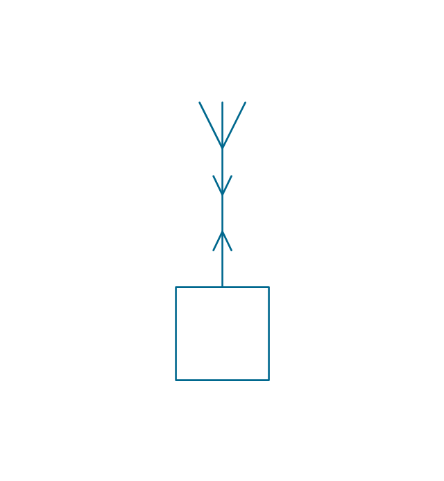
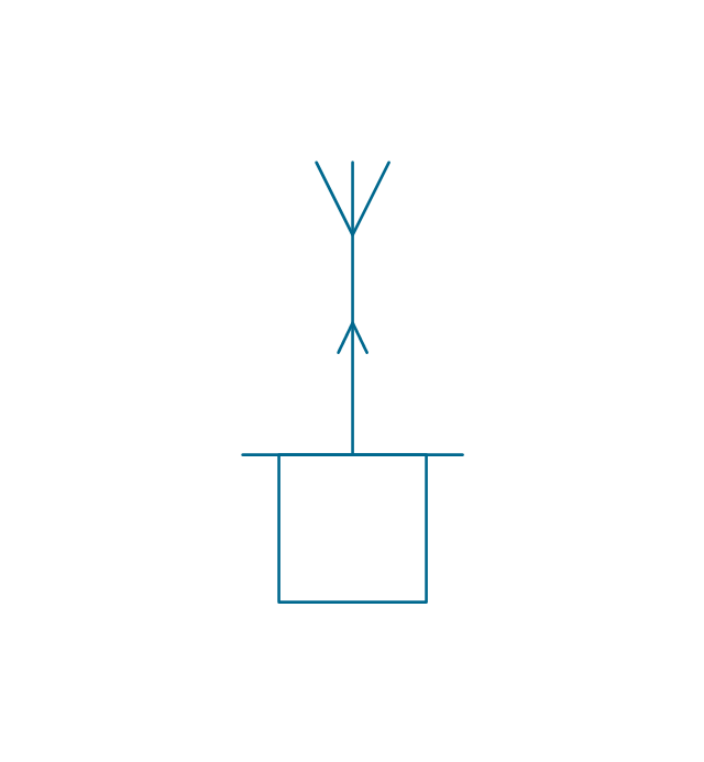
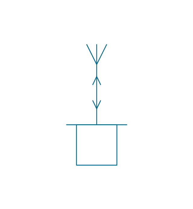
The Jackson Structured Programming (JSP) Diagram solution extends the functionality and drawing abilities of the ConceptDraw DIAGRAM software with set of illustrative JSP diagrams samples and large variety of predesigned vector objects of actions, processes, procedures, selection, iteration, as well as arrows and connectors to join the objects during Jackson structured development and designing Jackson structured programming diagrams, JSP diagram, Jackson structure diagram (JSD), Program structure diagram. The powerful abilities of this solution make the ConceptDraw DIAGRAM ideal assistant for programmers, software developers, structural programmers, computer engineers, applications constructors, designers, specialists in structured programming and Jackson systems design, and other technical, computer and software specialists.
Types of Flowcharts


This purchase order processing UML activity diagram was created on the base of activity diagram from the software architecture documentation wiki of the Software Engineering Institute (SEI) of Carnegie Mellon University (CMU).
[wiki.sei.cmu.edu/ sad/ index.php/ Image:PurchaseOrderActivityDiagram.png]
"A purchase order (PO) is a commercial document and first official offer issued by a buyer to a seller, indicating types, quantities, and agreed prices for products or services. Acceptance of a purchase order by a seller forms a contract between the buyer and seller, so no contract exists until the purchase order is accepted. It is used to control the purchasing of products and services from external suppliers.
Creating a purchase order is typically the first step of the purchase to pay process in an ERP system." [Purchase order. Wikipedia]
This purchase order processing UML activity diagram example was created using the ConceptDraw PRO diagramming and vector drawing software extended with the ATM UML Diagrams solution from the Software Development area of ConceptDraw Solution Park.
UML activity diagram of purchase order processing

The vector stencils library "Stations" contains 110 symbols of communications equipment, generating, transmitting and receiving stations; substations; satellites; and power plants.
Use these shapes for drawing diagrams of power generation and distribution and radio relay systems in the ConceptDraw PRO diagramming and vector drawing software extended with the Electrical Engineering solution from the Engineering area of ConceptDraw Solution Park.
www.conceptdraw.com/ solution-park/ engineering-electrical
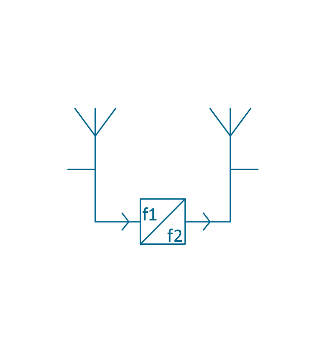
Radio relay station
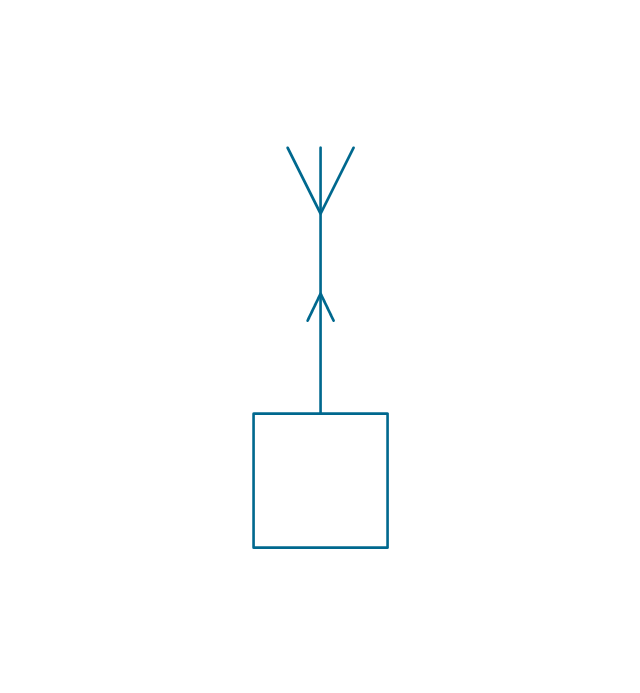
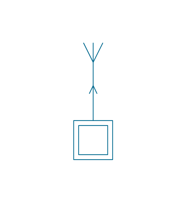
Transmission radio station
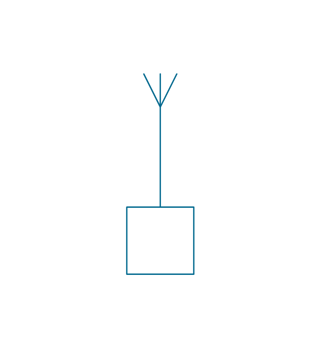
Radio station
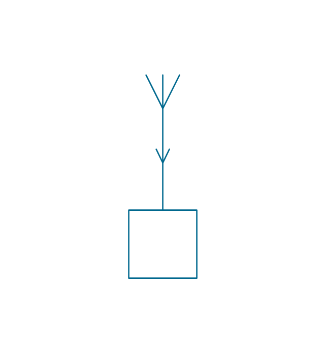
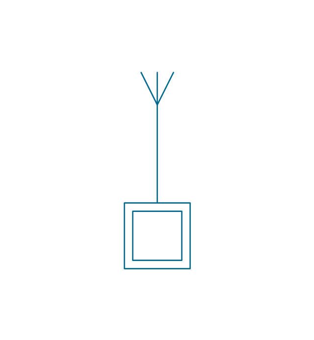
Reception radio station
Alternating radio station
Simultaneous radio station
End radio station

End radio station 2

General radio station

General radio station 2

Repeater radio station

Repeater radio station 2

Portable station

Transmission portable station
Reception portable station

Alternating portable station
Simultaneous portable station
Mobile simultaneous station

Mobile alternating station

Mobile reception station

Mobile transmission station

Mobile station

Direction finding station

Radio beacon station
Simultaneous controlling station
Alternating controlling station
Reception controlling station
Transmission controlling station
Controlling station
End station

Repeater station

Subscriber equipment

Subscriber equipment 2

Passive relay

Active space station

Passive space station

Space station

Earth tracking station
Earth communication service

Telegraph repeater, one-way simplex
Telegraph repeater, two-way simplex

Telegraph repeater, duplex

Telegraph repeater, one-way simplex 2
Telegraph repeater, two-way simplex 2
Telegraph repeater, duplex 2
Telegraph repeater qualifiers, polar direct-current (double current)
-stations---vector-stencils-library.png--diagram-flowchart-example.png)
Telegraph repeater qualifier, neutral direct-current (single current) +/o
-+/o-stations---vector-stencils-library.png--diagram-flowchart-example.png)
Telegraph repeater qualifier, neutral direct-current (single current) -/o
--/o-stations---vector-stencils-library.png--diagram-flowchart-example.png)
Telegraph equipment

Telegraph transmitter

Telegraph receiver

Two-way simplex telegraph

Duplex telegraph

Telegraph transmitter 2

Telegraph receiver 2

Two-way simplex telegraph 2

Duplex telegraph 2

Telegraph equipment qualifier, tape printing

Telegraph equipment qualifier, tape perforating

Telegraph equipment qualifier, tape printing/perforating

Telegraph equipment qualifier, page printing

Telegraph equipment qualifier, keyboard

Telegraph equipment qualifier, facsimile

Telephone

Dial telephone

Push-button telephone

Multiple lines telephone

Coin box telephone

Speaker phone

Amplified phone

Generating station (in service)
-stations---vector-stencils-library.png--diagram-flowchart-example.png)
Generating station (planned)
-stations---vector-stencils-library.png--diagram-flowchart-example.png)
Electric heat station (in service)
-stations---vector-stencils-library.png--diagram-flowchart-example.png)
Electric heat station (planned)
-stations---vector-stencils-library.png--diagram-flowchart-example.png)
Hydroelectric station (planned)
-stations---vector-stencils-library.png--diagram-flowchart-example.png)
Hydroelectric station (in service)
-stations---vector-stencils-library.png--diagram-flowchart-example.png)
Hydroelectric station (planned) 2
-2-stations---vector-stencils-library.png--diagram-flowchart-example.png)
Hydroelectric station (in service) 2
-2-stations---vector-stencils-library.png--diagram-flowchart-example.png)
Hydroelectric station (planned) 3
-3-stations---vector-stencils-library.png--diagram-flowchart-example.png)
Hydroelectric station (in service) 3
-3-stations---vector-stencils-library.png--diagram-flowchart-example.png)
Hydroelectric station (planned) 4
-4-stations---vector-stencils-library.png--diagram-flowchart-example.png)
Hydroelectric station (in service) 4
-4-stations---vector-stencils-library.png--diagram-flowchart-example.png)
Thermoelectric station (planned)
-stations---vector-stencils-library.png--diagram-flowchart-example.png)
Thermoelectric station (in service)
-stations---vector-stencils-library.png--diagram-flowchart-example.png)
Coal fueled station (planned)
-stations---vector-stencils-library.png--diagram-flowchart-example.png)
Coal fueled station (in service)
-stations---vector-stencils-library.png--diagram-flowchart-example.png)
Oil/gas fueled station (planned)
-stations---vector-stencils-library.png--diagram-flowchart-example.png)
Oil/gas fueled station (in service)
-stations---vector-stencils-library.png--diagram-flowchart-example.png)
Nuclear station (planned)
-stations---vector-stencils-library.png--diagram-flowchart-example.png)
Nuclear station (in service)
-stations---vector-stencils-library.png--diagram-flowchart-example.png)
Geothermic station (planned)
-stations---vector-stencils-library.png--diagram-flowchart-example.png)
Geothermic station (in service)
-stations---vector-stencils-library.png--diagram-flowchart-example.png)
Solar station (planned)
-stations---vector-stencils-library.png--diagram-flowchart-example.png)
Solar station (in service)
-stations---vector-stencils-library.png--diagram-flowchart-example.png)
Wind station (planned)
-stations---vector-stencils-library.png--diagram-flowchart-example.png)
Wind station (in service)
-stations---vector-stencils-library.png--diagram-flowchart-example.png)
Converting substation (in service)
-stations---vector-stencils-library.png--diagram-flowchart-example.png)
Converting substation (planned)
-stations---vector-stencils-library.png--diagram-flowchart-example.png)
Substation (planned)
-stations---vector-stencils-library.png--diagram-flowchart-example.png)
Substation (in service)
-stations---vector-stencils-library.png--diagram-flowchart-example.png)
Prime mover, reciprocating engine

Prime mover, gas turbine

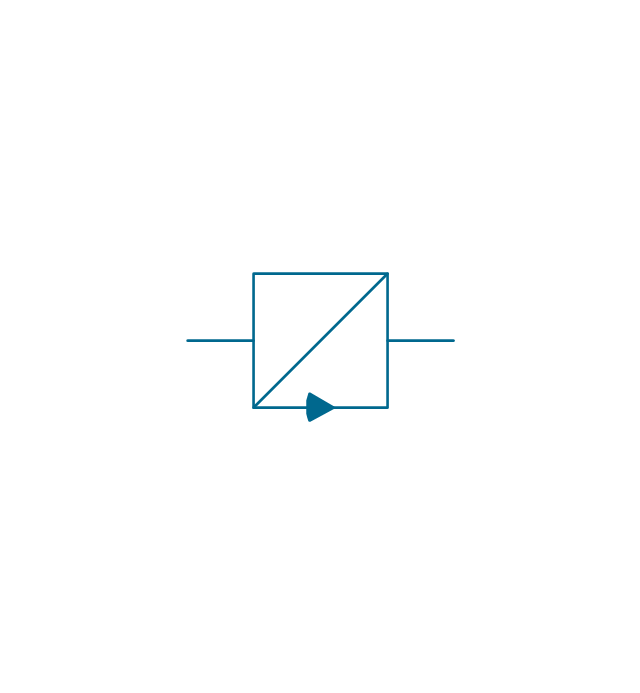
Converting station

Converting station 2

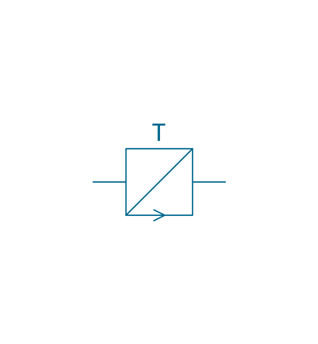
Switching station

Switching station 2

Rectifier substation (planned)
-stations---vector-stencils-library.png--diagram-flowchart-example.png)
Rectifier substation (in service)
-stations---vector-stencils-library.png--diagram-flowchart-example.png)
Plasma station MHD (planned)
-stations---vector-stencils-library.png--diagram-flowchart-example.png)
Plasma station MHD (in service)
-stations---vector-stencils-library.png--diagram-flowchart-example.png)
- Entity-Relationship Diagram (ERD) | Sample Questions And ...
- Drow The Er Digram Of Banking System In Sad Paf
- Data Flow Diagram Symbols. DFD Library | UML Use Case Diagram ...
- Data Flow Diagram Symbols. DFD Library | Geo Map - South ...
- Bank Dfd In Sad
- Draw A System Model For A School System Using Structure Chart Sad
- Entity-Relationship Diagram (ERD) | Data Flow Diagrams (DFD ...
- Entity-Relationship Diagram (ERD) | Order process - BPMN 2.0 ...
- Fire and Emergency Plans | Entity Relationship Diagram - ERD ...
- Flowchart Definition | Data Flow Diagram Symbols. DFD Library ...
- Fire and Emergency Plans | Entity Relationship Diagram - ERD ...
- Software For Drow ER Diagram
- Food Court | Entity-Relationship Diagram (ERD) | Cafe and ...
- Structured Systems Analysis and Design Method. SSADM with ...
- (SSADM) with ConceptDraw DIAGRAM | Data Structure In Sad
- The Logical Data Structuring Techniques In Sad
- Logical Data Structuring Techniques
- Uml Activity Order Process Diagram Example
- Entity Relationship Diagram Software | Material Requisition ...