Sign Making Software
ConceptDraw PRO is a powerful sign making software thanks to the vector stencils library "Recreation signs". This library is included in the Directional Maps solution from the Maps area of ConceptDraw Solution Park. Sign making software is very useful tool for professional sign-making business. Use ConceptDraw PRO and make sure that now sign making is easier and timesaving than ever!BPMN 2.0
ConceptDraw PRO diagramming and vector drawing software offers the Business Process Diagram Solution from the Business Processes Area of ConceptDraw Solution Park with powerful tools to help you easy represent the business processes and create the business process diagrams based on BPMN 2.0 standard.Cisco Buildings. Cisco icons, shapes, stencils and symbols
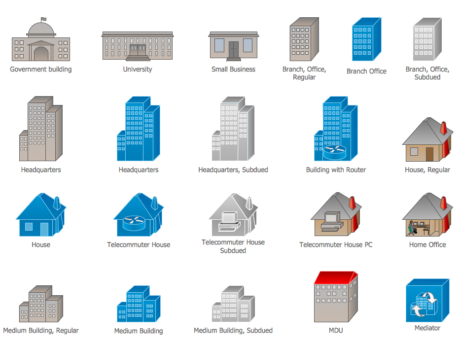
Cisco icons are globally recognized and generally accepted as standard for network icon topologies. The ConceptDraw vector stencils library "Cisco buildings" contains 21 symbols for drawing the computer network diagrams using the ConceptDraw PRO diagramming and vector drawing software.Total Quality Management Definition
The Total Quality Management Diagram solution helps you and your organization visualize business and industrial processes. Create Total Quality Management diagrams for business process with ConceptDraw software.Diagramming Software for UML Composite Structure Diagrams
UML Composite Structure Diagram shows the internal structure of a class and the possible interactions at this structure.
UML Use Case Diagrams
ConceptDraw has several examples that help you to start using software for designing UML Use Case Diagrams.
Network Topology Mapper
Network Topology in communication networks, a topology is a usually schematic description of the arrangement of a network, including its nodes and connecting lines. There are two ways of defining network geometry: the physical topology and the logical topology. Network Topology Mapper offers extensive drawing tools professional-looking network diagrams quickly and easily allowing you to clearly represent and communicate network architecture, topology, and design to engineers, stakeholders and end-users.UML Class Diagram Notation
When it comes to system construction, a class diagram is the most widely used diagram. UML Class Diagrams is a type of static structure diagram that is used for general conceptual modeling of the systematics of the application. Such a diagram would illustrate the object-oriented view of a system . The object orientation of a system is indicated by a class diagram. It describes the structure of a system by showing the general issues,classes of a system, attributes, operations, interfaces, inheritance, and the relationships between them.- How To Design Erd For Tour Management System
- Convert Dfd To Erd
- Dfd And Er Diagram Of Library Management System
- Usecase Diagram For Tourist Guider
- UML Class Diagram Generalization Example UML Diagrams | Entity ...
- Process Of Er Diagram For Transport Management System Ppt
- Components of ER Diagram | Entity-Relationship Diagram ( ERD ...
- UML Block Diagram | About UML | Software and Database Design ...
- Dataflow Diagram Of Tourist Guide
- Tourist Guide Flowchart
- Fire Exit Plan. Building Plan Examples | Design elements ...
- UML Tool & UML Diagram Examples | Entity Relationship Diagram ...
- AWS Architecture Diagrams | Timing diagram | UML Class Diagram ...
- Basic Flowchart Symbols and Meaning | ERD Symbols and ...
- UML Deployment Diagram. Diagramming Software for Design UML ...
- Sign Making Software | Restaurant Floor Plans Software | How To ...
- SWOT analysis for a small independent bookstore | Landmarks ...
- Determine groundwater - IDEF0 diagram | Fire and emergency ...
- Diagramming Software for Design UML Use Case Diagrams | UML ...
- Design elements - Walls, shell and structure | Entity Relationship ...


