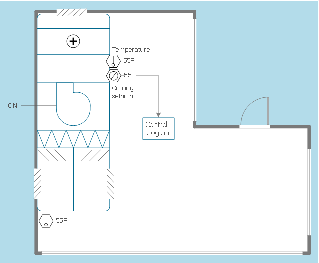
This HVAC floor plan sample illustrates the temperature sensors of air handler digital thermostat control.
"A thermostat is a component of a control system which senses the temperature of a system so that the system's temperature is maintained near a desired setpoint. The thermostat does this by switching heating or cooling devices on or off, or regulating the flow of a heat transfer fluid as needed, to maintain the correct temperature. The name is derived from the Greek words thermos "hot" and statos "a standing".
A thermostat may be a control unit for a heating or cooling system or a component part of a heater or air conditioner. Thermostats can be constructed in many ways and may use a variety of sensors to measure the temperature. The output of the sensor then controls the heating or cooling apparatus. A thermostat may switch on and off at temperatures either side of the setpoint the extent of the difference is known as hysteresis and prevents too frequent switching of the controlled equipment." [Thermostat. Wikipedia]
The HVAC plan example "Digital unit ventilator control" was created using the ConceptDraw PRO diagramming and vector drawing software extended with the HVAC Plans solution from the Building Plans area of ConceptDraw Solution Park.
- HVAC Plans | Block diagram - Automotive HVAC system | How to ...
- HVAC Plans | How to Create a HVAC Plan | HVAC Marketing Plan ...
- HVAC Plans | How to Create a HVAC Plan | Air handler- HVAC plan ...
- Design elements - HVAC control equipment | Building Drawing ...
- Sample Drawing Of Floor Plan With Air Conditioning System
- Design elements - HVAC ductwork | Interior Design Registers, Drills ...
- Mechanical Drawing Symbols | Design elements - Fluid power ...
- Block diagram - Automotive HVAC system | HVAC Plans | Cable TV ...
- Design elements - HVAC equipment | Block Diagrams | Block ...
- Block diagram - Automotive HVAC system | Functional Block ...
- HVAC Plans | HVAC Marketing Plan | Building Drawing Software for ...
- Working Of Ac With Block Diagram
- Block diagram - Automotive HVAC system | Functional Block ...
- Hvac Symbols
- HVAC Plans | Workflow diagram - Weather forecast | Correlation ...
- HVAC Plans | Design elements - HVAC controls | Fishbone Diagram ...
- HVAC Plans | Block diagram - Automotive HVAC system | HVAC ...
- Interior Design Registers, Drills and Diffusers - Design Elements ...
- Mechanical Drawing Symbols | Mechanical Engineering | Design ...
