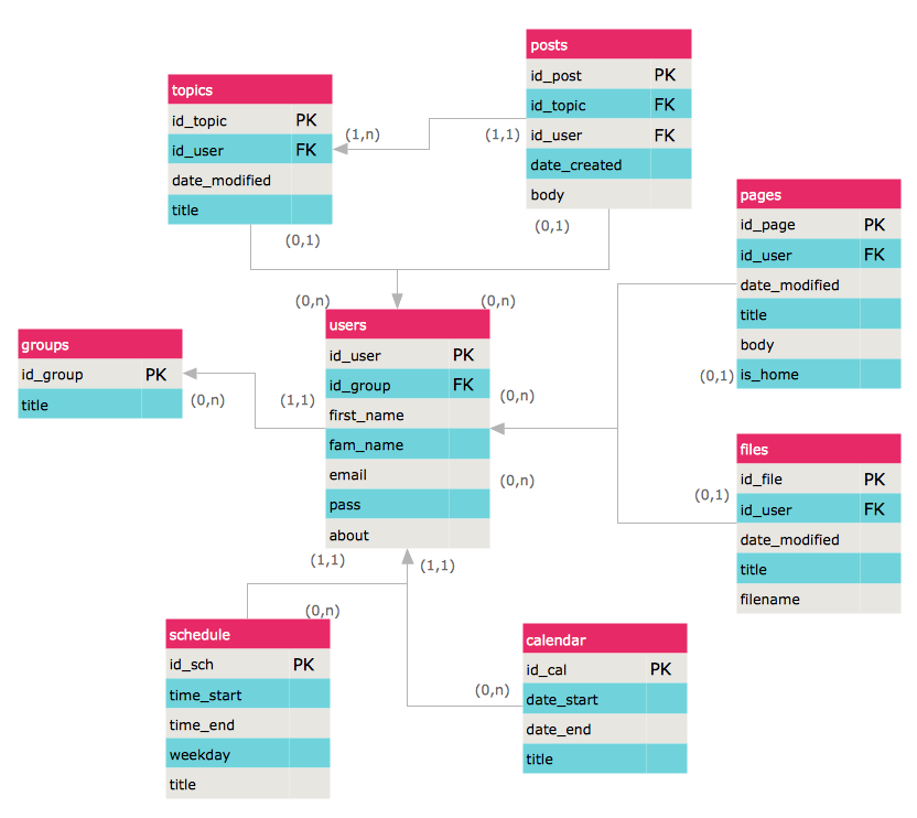
 Entity-Relationship Diagram (ERD)
An Entity-Relationship Diagram (ERD) is a visual presentation of entities and relationships. That type of diagrams is often used in the semi-structured or unstructured data in databases and information systems. At first glance ERD is similar to a flowch
 Software Development Area
Solutions from the Software Development Area of ConceptDraw Solution Park collect templates, samples and libraries of vector stencils for drawing the software engineering diagrams and user interface design prototypes.
 AWS Architecture Diagrams
AWS Architecture Diagrams with powerful drawing tools and numerous predesigned Amazon icons and AWS simple icons is the best for creation the AWS Architecture Diagrams, describing the use of Amazon Web Services or Amazon Cloud Services, their application for development and implementation the systems running on the AWS infrastructure. The multifarious samples give you the good understanding of AWS platform, its structure, services, resources and features, wide opportunities, advantages and benefits from their use; solution’s templates are essential and helpful when designing, description and implementing the AWS infrastructure-based systems. Use them in technical documentation, advertising and marketing materials, in specifications, presentation slides, whitepapers, datasheets, posters, etc.
HelpDesk
How to Create an ERD Diagram
ERD (entity relationship diagram) is used to show the logical structure of databases. It represents the interrelationships between components of database (entities). Entity relationship diagrams are a widely used in software engineering. Using ERD software engineers can control the every aspect of database development. ER diagram can be used as guide for testing and communicating before the release of software product. ERD displays data as entities that are connected with connections that show the relationships between entities. There is some ERD notations used by data bases developers for representing the relationships between the data objects. ConceptDraw PRO and its ERD solution allow you to build ERD diagram of any notation.
 Data Flow Diagrams (DFD)
Data Flow Diagrams solution extends ConceptDraw PRO software with templates, samples and libraries of vector stencils for drawing the data flow diagrams (DFD).
Basic Flowchart Symbols and Meaning
Flowcharts are the best for visually representation the business processes and the flow of a custom-order process through various departments within an organization. ConceptDraw PRO diagramming and vector drawing software extended with Flowcharts solution offers the full set of predesigned basic flowchart symbols which are gathered at two libraries: Flowchart and Flowcharts Rapid Draw. Among them are: process, terminator, decision, data, document, display, manual loop, and many other specific symbols. The meaning for each symbol offered by ConceptDraw gives the presentation about their proposed use in professional Flowcharts for business and technical processes, software algorithms, well-developed structures of web sites, Workflow diagrams, Process flow diagram and correlation in developing on-line instructional projects or business process system. Use of ready flow chart symbols in diagrams is incredibly useful - you need simply drag desired from the libraries to your document and arrange them in required order. There are a few serious alternatives to Visio for Mac, one of them is ConceptDraw PRO. It is one of the main contender with the most similar features and capabilities.
- Document On Examples Of Entity Relationship In Database On
- Entity - Relationship Diagram (ERD) | Audio and Video Connectors ...
- Audio, Video , Media | Entity - Relationship Diagram (ERD) | Artwork ...
- Audio and Video Connectors | Audio, Video , Media | Illustration ...
- Er Diagram Of Audio Video
- Entity - Relationship Diagram (ERD) | Audio, Video , Media | Android ...
- Audio and Video Connectors | Entity - Relationship Diagram (ERD ...
- DFD Library System | Data Flow Diagrams (DFD) | Audio, Video ...
- Entity - Relationship Diagram (ERD)
- Chen's ERD of MMORPG | Audio and Video Connectors | Fishbone ...
- Audio and Video Connectors | Audio, Video , Media | ConceptDraw ...
- Audio, Video , Media | Entity - Relationship Diagram (ERD ...
- Audio and Video Connectors | Illustration | Entity - Relationship ...
- Audio and Video Connectors | Entity - Relationship Diagram (ERD ...
- Data Flow Diagrams (DFD) | Audio, Video , Media | Fishbone ...
- Audio, Video , Media | GUI Prototyping with ConceptDraw PRO | DFD ...
- Entity - Relationship Diagram (ERD) | Social Media Response ...
- Data Flow Diagrams (DFD) | Audio, Video , Media | UML Activity ...
- Audio, Video , Media | UML Deployment Diagram | AWS Architecture ...

