The vector stencils library "Cisco routers" contains 27 symbols of routers for drawing Cisco computer network diagrams.
"When multiple routers are used in interconnected networks, the routers exchange information about destination addresses using a dynamic routing protocol. Each router builds up a table listing the preferred routes between any two systems on the interconnected networks. A router has interfaces for different physical types of network connections, (such as copper cables, fiber optic, or wireless transmission). It also contains firmware for different networking Communications protocol standards. Each network interface uses this specialized computer software to enable data packets to be forwarded from one protocol transmission system to another.
Routers may also be used to connect two or more logical groups of computer devices known as subnets, each with a different sub-network address. The subnets addresses recorded in the router do not necessarily map directly to the physical interface connections." [Router (computing). Wikipedia]
The symbols example "Cisco routers - Vector stencils library" was created using the ConceptDraw PRO diagramming and vector drawing software extended with the Cisco Network Diagrams solution from the Computer and Networks area of ConceptDraw Solution Park.
www.conceptdraw.com/ solution-park/ computer-networks-cisco
Router

Router, subdued

Router with silicon switch

Wavelength router

NetFlow router

uBR 910

Broadband router

Gigabit switch ATM tag router

ATM tag switch router

ATM router

NetFlow router

Cisco 7505

Cisco 7507

Cisco 7500 ARS (7513)
-cisco-routers---vector-stencils-library.png--diagram-flowchart-example.png)
Voice enabled router

TDM router

IP telephony router

IAD router

Content service router

Cisco storage router

Router with firewall

Wireless router

ASR 1000 series

ATM 3800

AXP

Cable modem

Ground terminal

Cisco Routers. Cisco icons, shapes, stencils and symbols

Cisco Network Topology. Cisco icons, shapes, stencils and symbols

The vector stencils library "Cisco routers" contains 27 symbols of routers for drawing Cisco computer network diagrams.
"When multiple routers are used in interconnected networks, the routers exchange information about destination addresses using a dynamic routing protocol. Each router builds up a table listing the preferred routes between any two systems on the interconnected networks. A router has interfaces for different physical types of network connections, (such as copper cables, fiber optic, or wireless transmission). It also contains firmware for different networking Communications protocol standards. Each network interface uses this specialized computer software to enable data packets to be forwarded from one protocol transmission system to another.
Routers may also be used to connect two or more logical groups of computer devices known as subnets, each with a different sub-network address. The subnets addresses recorded in the router do not necessarily map directly to the physical interface connections." [Router (computing). Wikipedia]
The symbols example "Cisco routers - Vector stencils library" was created using the ConceptDraw PRO diagramming and vector drawing software extended with the Cisco Network Diagrams solution from the Computer and Networks area of ConceptDraw Solution Park.
www.conceptdraw.com/ solution-park/ computer-networks-cisco
"When multiple routers are used in interconnected networks, the routers exchange information about destination addresses using a dynamic routing protocol. Each router builds up a table listing the preferred routes between any two systems on the interconnected networks. A router has interfaces for different physical types of network connections, (such as copper cables, fiber optic, or wireless transmission). It also contains firmware for different networking Communications protocol standards. Each network interface uses this specialized computer software to enable data packets to be forwarded from one protocol transmission system to another.
Routers may also be used to connect two or more logical groups of computer devices known as subnets, each with a different sub-network address. The subnets addresses recorded in the router do not necessarily map directly to the physical interface connections." [Router (computing). Wikipedia]
The symbols example "Cisco routers - Vector stencils library" was created using the ConceptDraw PRO diagramming and vector drawing software extended with the Cisco Network Diagrams solution from the Computer and Networks area of ConceptDraw Solution Park.
www.conceptdraw.com/ solution-park/ computer-networks-cisco
Router
Router, subdued
Router with silicon switch
Wavelength router
NetFlow router
uBR 910
Broadband router
Gigabit switch ATM tag router
ATM tag switch router
ATM router
NetFlow router
Cisco 7505
Cisco 7507
Cisco 7500 ARS (7513)
Voice enabled router
TDM router
IP telephony router
IAD router
Content service router
Cisco storage router
Router with firewall
Wireless router
ASR 1000 series
ATM 3800
AXP
Cable modem
Ground terminal
Hotel Network Topology Diagram


Network Glossary Definition


The vector stencils library "Cisco routers" contains 27 symbols of routers for drawing Cisco computer network diagrams.
"When multiple routers are used in interconnected networks, the routers exchange information about destination addresses using a dynamic routing protocol. Each router builds up a table listing the preferred routes between any two systems on the interconnected networks. A router has interfaces for different physical types of network connections, (such as copper cables, fiber optic, or wireless transmission). It also contains firmware for different networking Communications protocol standards. Each network interface uses this specialized computer software to enable data packets to be forwarded from one protocol transmission system to another.
Routers may also be used to connect two or more logical groups of computer devices known as subnets, each with a different sub-network address. The subnets addresses recorded in the router do not necessarily map directly to the physical interface connections." [Router (computing). Wikipedia]
The symbols example "Cisco routers - Vector stencils library" was created using the ConceptDraw PRO diagramming and vector drawing software extended with the Cisco Network Diagrams solution from the Computer and Networks area of ConceptDraw Solution Park.
www.conceptdraw.com/ solution-park/ computer-networks-cisco
"When multiple routers are used in interconnected networks, the routers exchange information about destination addresses using a dynamic routing protocol. Each router builds up a table listing the preferred routes between any two systems on the interconnected networks. A router has interfaces for different physical types of network connections, (such as copper cables, fiber optic, or wireless transmission). It also contains firmware for different networking Communications protocol standards. Each network interface uses this specialized computer software to enable data packets to be forwarded from one protocol transmission system to another.
Routers may also be used to connect two or more logical groups of computer devices known as subnets, each with a different sub-network address. The subnets addresses recorded in the router do not necessarily map directly to the physical interface connections." [Router (computing). Wikipedia]
The symbols example "Cisco routers - Vector stencils library" was created using the ConceptDraw PRO diagramming and vector drawing software extended with the Cisco Network Diagrams solution from the Computer and Networks area of ConceptDraw Solution Park.
www.conceptdraw.com/ solution-park/ computer-networks-cisco
Router
Router, subdued
Router with silicon switch
Wavelength router
NetFlow router
uBR 910
Broadband router
Gigabit switch ATM tag router
ATM tag switch router
ATM router
NetFlow router
Cisco 7505
Cisco 7507
Cisco 7500 ARS (7513)
Voice enabled router
TDM router
IP telephony router
IAD router
Content service router
Cisco storage router
Router with firewall
Wireless router
ASR 1000 series
ATM 3800
AXP
Cable modem
Ground terminal
Hotel Network Topology
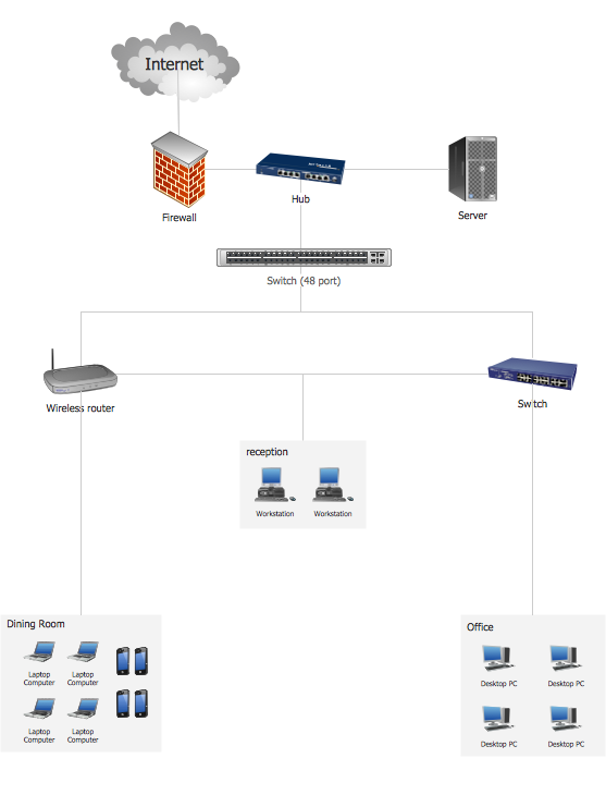
"In computer networks, networked computing devices pass data to each other along data connections. The connections (network links) between nodes are established using either cable media or wireless media. ...
Network computer devices that originate, route and terminate the data are called network nodes. Nodes can include hosts such as personal computers, phones, servers as well as networking hardware. ...
Network links.
The communication media used to link devices to form a computer network include electrical cable (HomePNA, power line communication, G.hn), optical fiber (fiber-optic communication), and radio waves (wireless networking). In the OSI model, these are defined at layers 1 and 2 - the physical layer and the data link layer.
A widely adopted family of communication media used in local area network (LAN) technology is collectively known as Ethernet. The media and protocol standards that enable communication between networked devices over Ethernet are defined by IEEE 802.3. Ethernet transmit data over both copper and fiber cables. Wireless LAN standards (e.g. those defined by IEEE 802.11) use radio waves, or others use infrared signals as a transmission medium. Power line communication uses a building's power cabling to transmit data. ...
Network nodes.
Apart from the physical communications media described above, networks comprise additional basic system building blocks, such as network interface controller (NICs), repeaters, hubs, bridges, switches, routers, modems, and firewalls." [Computer network. Wikipedia]
The network equipment and cabling layout floorplan template for the ConceptDraw PRO diagramming and vector drawing software is included in the Network Layout Floor Plans solution from the Computer and Networks area of ConceptDraw Solution Park.
LAN equipment and cabling layout floorplan template

"A computer network or data network is a telecommunications network that allows computers to exchange data. In computer networks, networked computing devices (network nodes) pass data to each other along data connections. The connections (network links) between nodes are established using either cable media or wireless media. The best-known computer network is the Internet.
Network devices that originate, route and terminate the data are called network nodes. Nodes can include hosts such as servers and personal computers, as well as networking hardware. Two devices are said to be networked when a device is able to exchange information with another device." [Computer network. Wikipedia]
This computer communication network diagram example was created using the ConceptDraw PRO diagramming and vector drawing software extended with the Computer and Networks solution from the Computer and Networks area of ConceptDraw Solution Park.
Network diagram

Network Gateway Router

Secure Wireless Network
Cisco Products Additional. Cisco icons, shapes, stencils and symbols

Network Hubs

The vector stencils library "Wireless networks" contains 82 icon symbols for drawing wireless computer network diagrams and equipment layout plans.
"A wireless network is any type of computer network that uses wireless data connections for connecting network nodes.
Wireless networking is a method by which homes, telecommunications networks and enterprise (business) installations avoid the costly process of introducing cables into a building, or as a connection between various equipment locations.
Wireless telecommunications networks are generally implemented and administered using radio communication. This implementation takes place at the physical level (layer) of the OSI model network structure.
Examples of wireless networks include cell phone networks, Wi-Fi local networks and terrestrial microwave networks." [Wireless network. Wikipedia]
The clip art example "Wireless networks - Vector stencils library" was created using the ConceptDraw PRO diagramming and vector drawing software extended with the Wireless Networks solution from the Computer and Networks area of ConceptDraw Solution Park.
www.conceptdraw.com/ solution-park/ wireless-networks
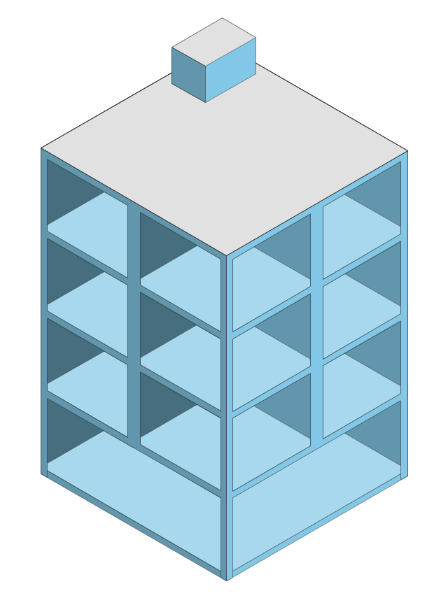
Building 1
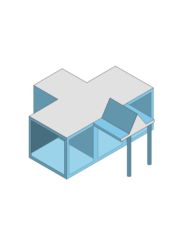
Building 4
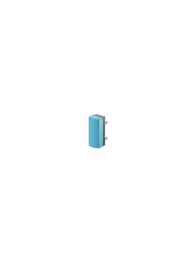
Coverage (Blue)
-wireless-networks---vector-stencils-library.png--diagram-flowchart-example.png)
Wireless Connectivity

Network Cloud
Cloud
Wi-Fi Access

Tree

Computer
Laptop Computer
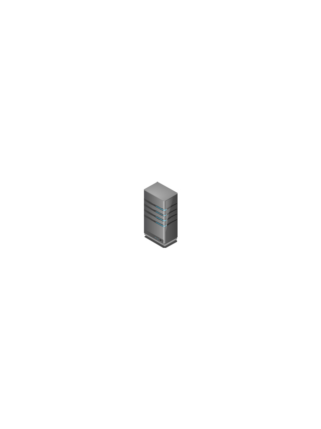
Server
Wireless Network Storage

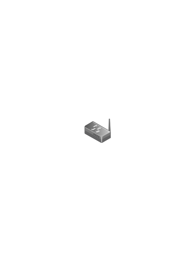
Router
Wireless Router
Switch
Wireless Access Point
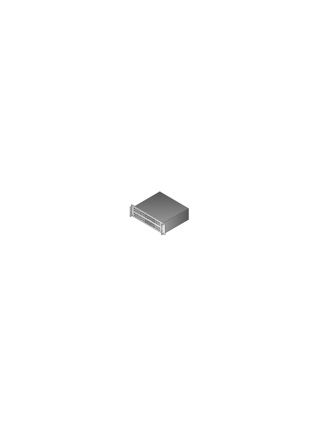
1U Hub Switch

2U Hub Switch
1U Server

2U Server

3U Server

4U Server

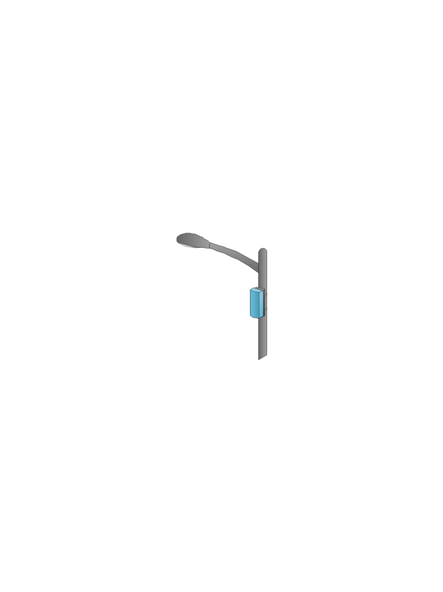
Outdoor Access Point

Indoor Access Point

Outdoor Wi-Fi Access Point

Access Point

Outdoor Mesh Node
Outdoor Mesh Node
Outdoor Access Node
Outdoor Access Node

Base Station
Cellular Phone

Outdoor Mesh Node
Active Directory Server
Smart WLAN Controller

Smart WLAN Controller

Smart Wi-Fi Access Point
Indoor Wi-Fi Access Point

Firewall
Coverage (Yellow)
-wireless-networks---vector-stencils-library.png--diagram-flowchart-example.png)
Coverage (O-Shaped)
-wireless-networks---vector-stencils-library.png--diagram-flowchart-example.png)
Outdoor Mesh Node
- Firewall Server Router Switch Cable
- Cisco Routers . Cisco icons, shapes, stencils and symbols | Cisco ...
- Router Modem Switch Hub
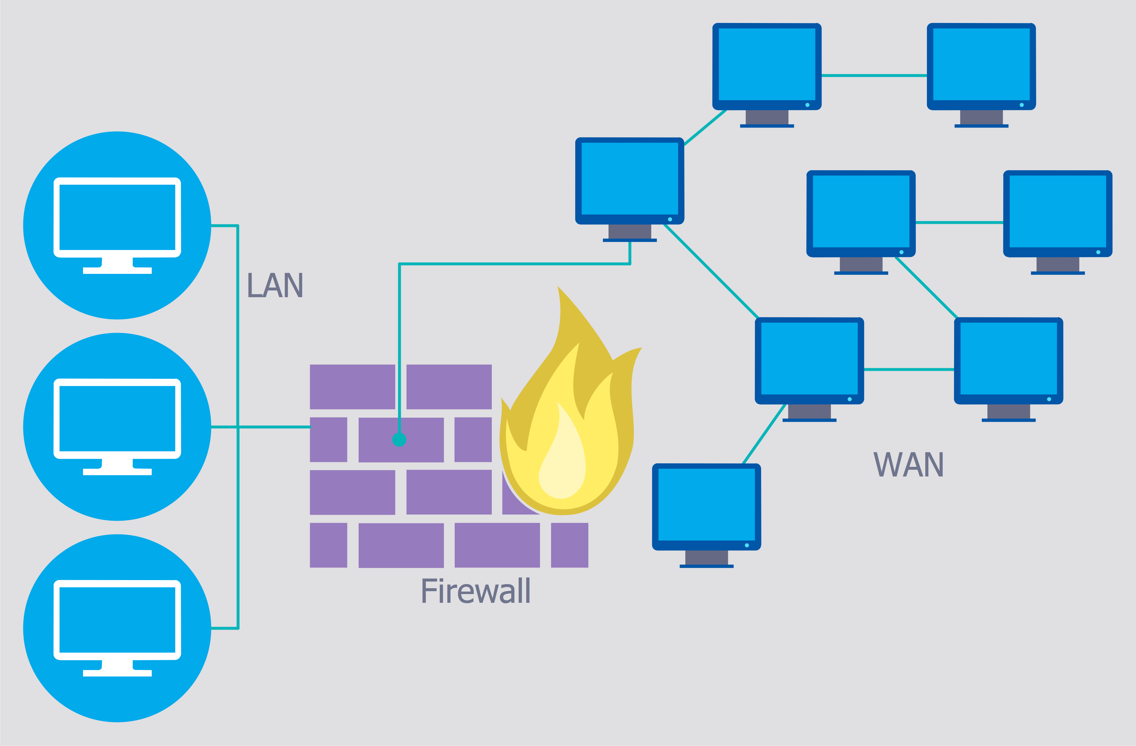
- Firewall between LAN and WAN | Hotel Network Topology Diagram ...
- Cisco routers - Vector stencils library | Network Glossary Definition ...
- Network Diagram Including Firewall Server And Router
- Network Gateway Router | Computer network - Vector stencils library ...
- Cisco Routers . Cisco icons, shapes, stencils and symbols | Network ...
- Cisco routers - Vector stencils library | Wireless router network ...
- Communication network diagram | Wireless router network diagram ...
- Star Network Topology | Fully Connected Network Topology ...
- Network equipment and cabling layout - Template | Network layout ...
- How To use Switches in Network Diagram | Star Network Topology ...
- Cisco network diagram - Template | Physical LAN and WAN diagram ...
- Cisco routers - Vector stencils library | Cisco Routers . Cisco icons ...
- Hardware Firewall Router
- Computer network - Vector stencils library | Network Glossary ...
- Computer network - Vector stencils library | Network wiring cable ...
- Cisco routers - Vector stencils library | Cisco routers - Vector stencils ...
- Hotel Network Topology Diagram | Star Network Topology | Wireless ...