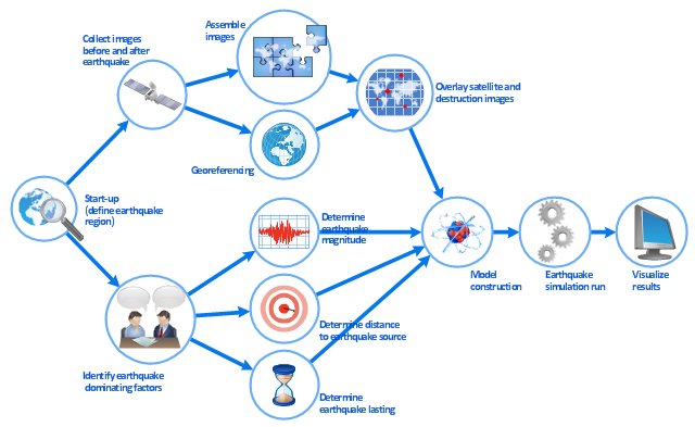
This work flow chart sample was redesigned from the picture "Simulation for earthquake disaster assessment" from the article "Simulation Workflows".
[iaas.uni-stuttgart.de/ forschung/ projects/ simtech/ sim-workflows.php]
" This simulation was developed to have an in depth understanding of the destructions and the decisions to be made in various phases of crisis management (Source: Mahdi Hashemi and Ali A. Alesheikh (2010). "Developing an agent based simulation model for earthquakes in the context of SDI." GSDI 12 World Conference. 19 – 22 October 2010. Singapour). The simulation process contains following major steps:
(1) All spatial information including satellite images (before and after the earthquake) and topographic/ cadastral maps of the area are mosaicked and georeferenced. The parts of the city that contain various levels of destructions are selected. Three types of features namely buildings, roads and recreational areas are classified and extracted from the satellite images.
(2) The governing factors of destructions are identified; a mathematical model that integrates the factors is constructed.
(3) The simulation is constructed for various parameter values (different earthquake strength, time elapses, etc.)" [iaas.uni-stuttgart.de/ forschung/ projects/ simtech/ sim-workflows.php]
The example "Workflow diagram - Earthquake disaster assessment" was drawn using the ConceptDraw PRO diagramming and vector drawing software extended with the Workflow Diagrams solution from the Business Processes area of ConceptDraw Solution Park.
ConceptDraw DIAGRAM Compatibility with MS Visio
The powerful diagramming and business graphics tools are now not exception, but the norm for today’s business, which develop in incredibly quick temp. But with the abundance of powerful business diagramming applications it is important to provide their compatibility for effective exchange the information between the colleagues and other people who maybe use different software in their work. During many years Microsoft Visio™ was standard file format for the business and now many people need the visual communication software tools that can read the Visio format files and also export to Visio format. The powerful diagramming and vector drawing software ConceptDraw DIAGRAM is ideal from the point of view of compatibility with MS Visio. Any ConceptDraw DIAGRAM user who have the colleagues that use MS Visio or any who migrates from Visio to ConceptDraw DIAGRAM , will not have any problems. The VSDX (Visio′s open XML file format) and VDX formatted files can be easily imported and exported by ConceptDraw DIAGRAM , you can see video about this possibility.Diagrama de Topologia
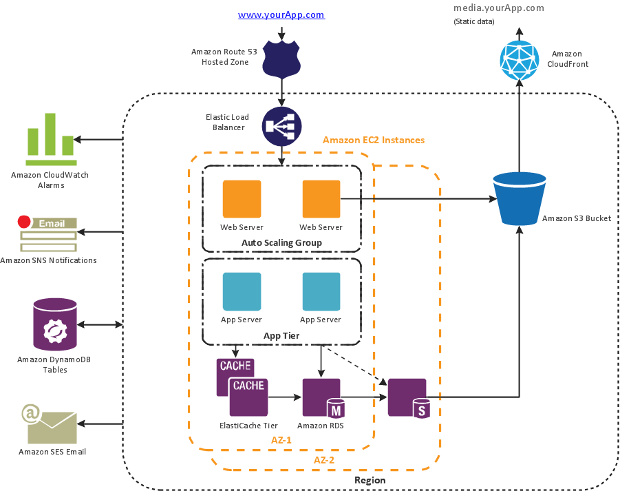
PRO is a powerful drawing tool that changes the way diagrams are produced. ConceptDraw Arrows10 Technology - This is more than enough versatility to draw any type of diagram with any degree of complexity. Diagrama de Topologia or Topology Diagram helps you see the big picture as you develop a service.ConceptDraw Arrows10 Technology
With ConceptDraw Arrows10 Technology - You can delete a single connector, by using the Delete key. If you need to delete more than a single connector in a complex diagram that contains many relations there is a special Delete Links tool which deletes the connectors only, no other drawing objects are deleted.- Types of Flowchart - Overview | Earthquake disaster assessment ...
- Types of Flowchart - Overview | Earthquake disaster assessment ...
- Process Flowchart | Types of Flowchart - Overview | The Best ...
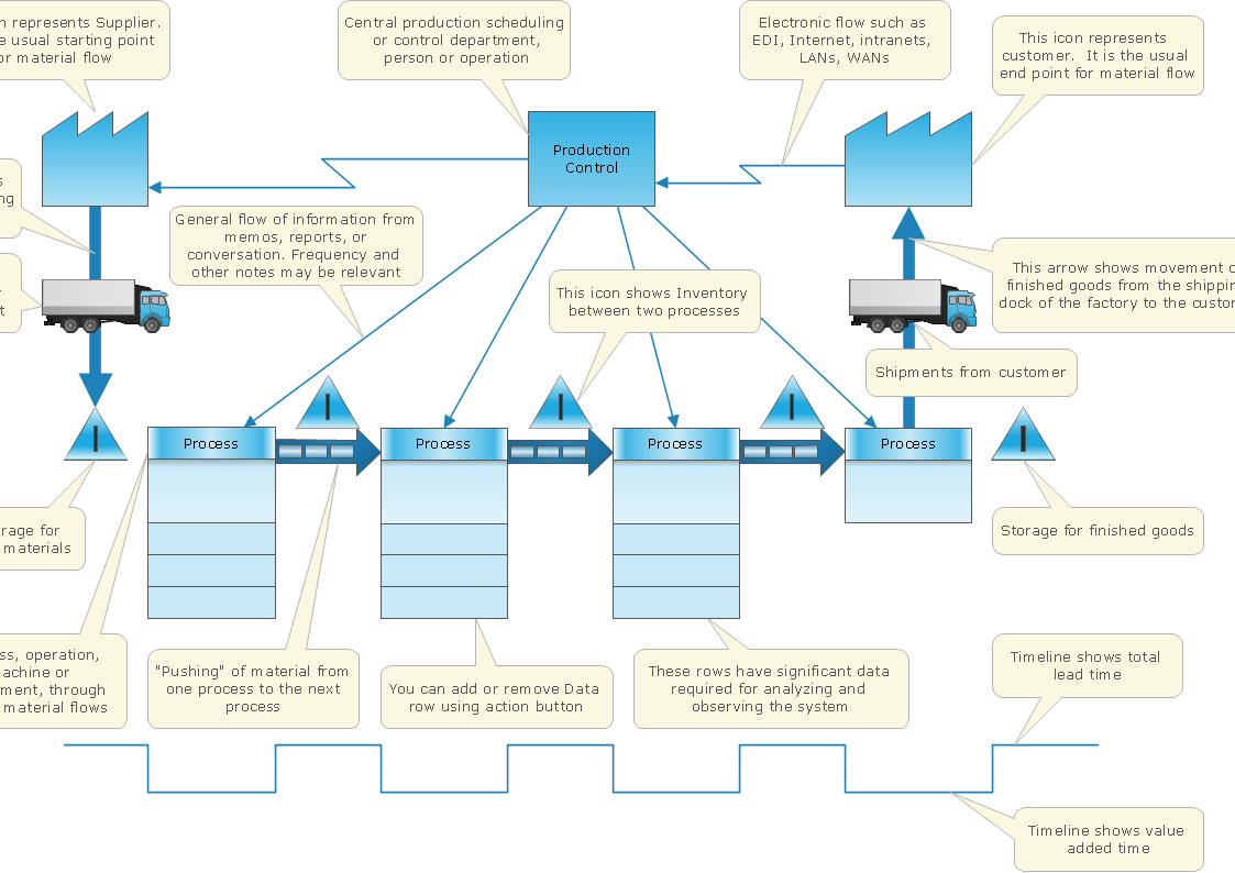
- Types of Flowchart - Overview | Value Stream Mapping for the Lean ...
- Process Flowchart | Earthquake disaster assessment - Workflow ...
- Charts On Disaster Management
- Earthquake disaster assessment - Workflow diagram | Army Flow ...
- Types of Flowchart - Overview | Work Flow Diagram | Emergency ...
- Emergency management exercise cycle | Flow chart Example ...
- Earthquake disaster assessment - Workflow diagram | Work Flow ...
- Types of Flowchart - Overview | Cross-Functional Flowcharts ...
- Earthquake disaster assessment - Workflow diagram | Work Flow ...
- Process Flowchart | Earthquake disaster assessment - Workflow ...
- UML Diagram | Diagram Flow Chart | Basic Diagramming ...
- Types of Flowchart - Overview | Emergency Plan | Chart On Disaster ...
- Types of Flowchart - Overview | How To Create Home Plan with ...
- Types of Flowchart - Overview | IDEF0 Diagrams | Cisco Network ...
- Chart On Disaster Management
- Types of Flowchart - Overview | Emergency Plan | Cross-Functional ...


