The vector stencils library "Plane geometry" contains 27 plane geometric figures.
Use these shapes to draw your geometrical diagrams and illustrations in the ConceptDraw PRO diagramming and vector drawing software extended with the Mathematics solution from the Science and Education area of ConceptDraw Solution Park.
Use these shapes to draw your geometrical diagrams and illustrations in the ConceptDraw PRO diagramming and vector drawing software extended with the Mathematics solution from the Science and Education area of ConceptDraw Solution Park.
Circular sector
Right triangle
Rectangle

Square

Pentagon
Isosceles trapezium
Parallelogram
Trapezium
Three-pointed star

Four-pointed star

Five-pointed star

Six-pointed star

Seven-pointed star

Eight-pointed star

Triangle
Equilateral triangle
Right triangle 2
Right triangle, angle box
Right triangle 3
Hexagon

Regular hexagon

Regular pentagon
Regular heptagon
Regular octagon
Rhombus

Circle

Ellipse

The vector stencils library "Plane geometry" contains 27 plane geometric figures.
Use these shapes to draw your geometrical diagrams and illustrations in the ConceptDraw PRO diagramming and vector drawing software extended with the Mathematics solution from the Science and Education area of ConceptDraw Solution Park.
Use these shapes to draw your geometrical diagrams and illustrations in the ConceptDraw PRO diagramming and vector drawing software extended with the Mathematics solution from the Science and Education area of ConceptDraw Solution Park.
Circular sector
Right triangle
Rectangle
Square
Pentagon
Isosceles trapezium
Parallelogram
Trapezium
Three-pointed star
Four-pointed star
Five-pointed star
Six-pointed star
Seven-pointed star
Eight-pointed star
Triangle
Equilateral triangle
Right triangle 2
Right triangle, angle box
Right triangle 3
Hexagon
Regular hexagon
Regular pentagon
Regular heptagon
Regular octagon
Rhombus
Circle
Ellipse
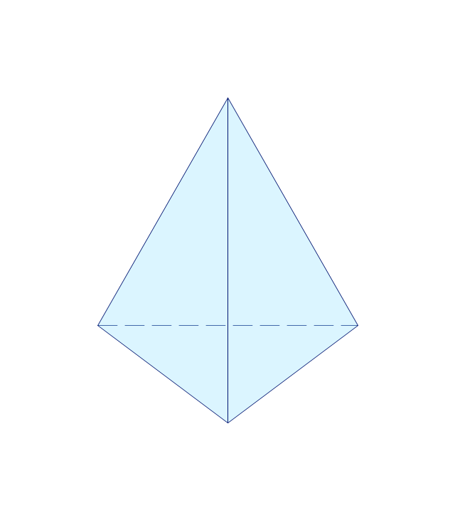
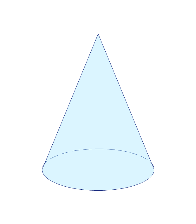
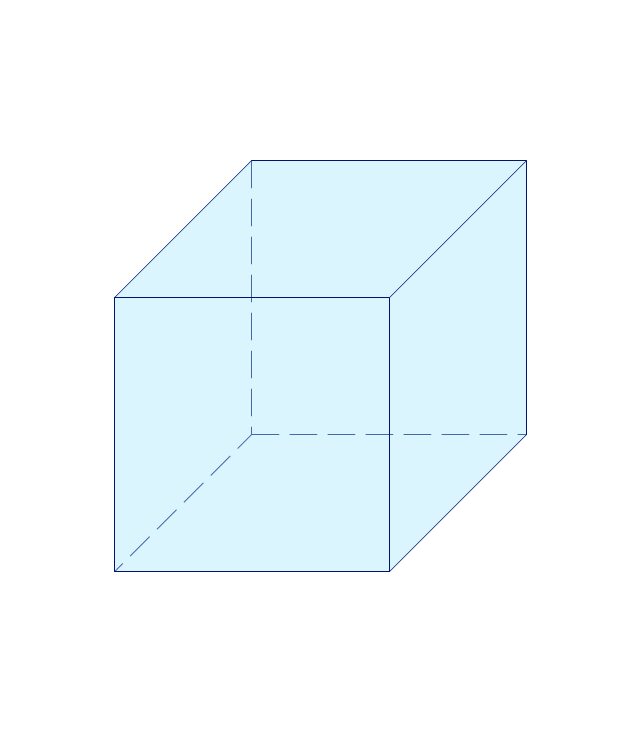
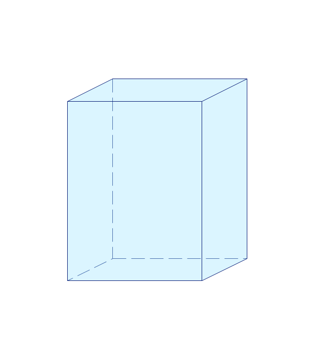
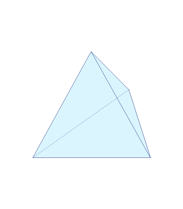
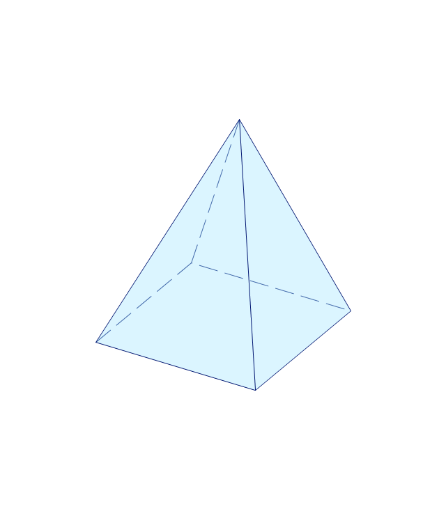
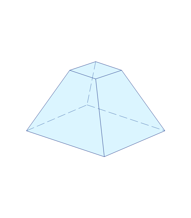
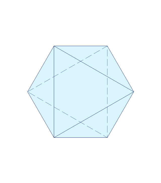
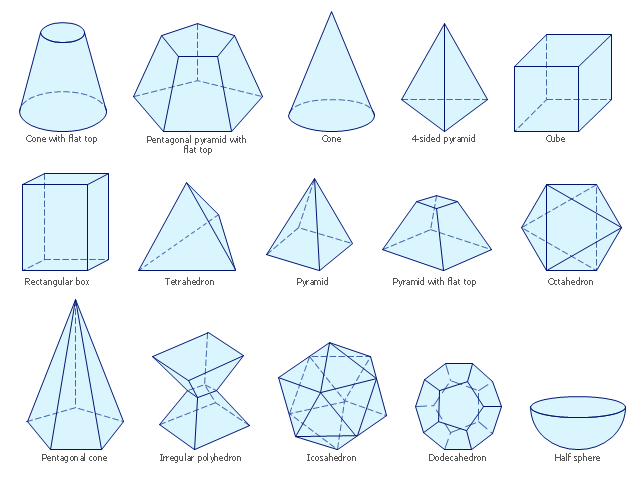
The vector stencils library "Solid geometry" contains 15 shapes of solid geometric figures.
Use these shapes to draw your geometrical diagrams and illustrations in the ConceptDraw PRO diagramming and vector drawing software extended with the Mathematics solution from the Science and Education area of ConceptDraw Solution Park.
Use these shapes to draw your geometrical diagrams and illustrations in the ConceptDraw PRO diagramming and vector drawing software extended with the Mathematics solution from the Science and Education area of ConceptDraw Solution Park.
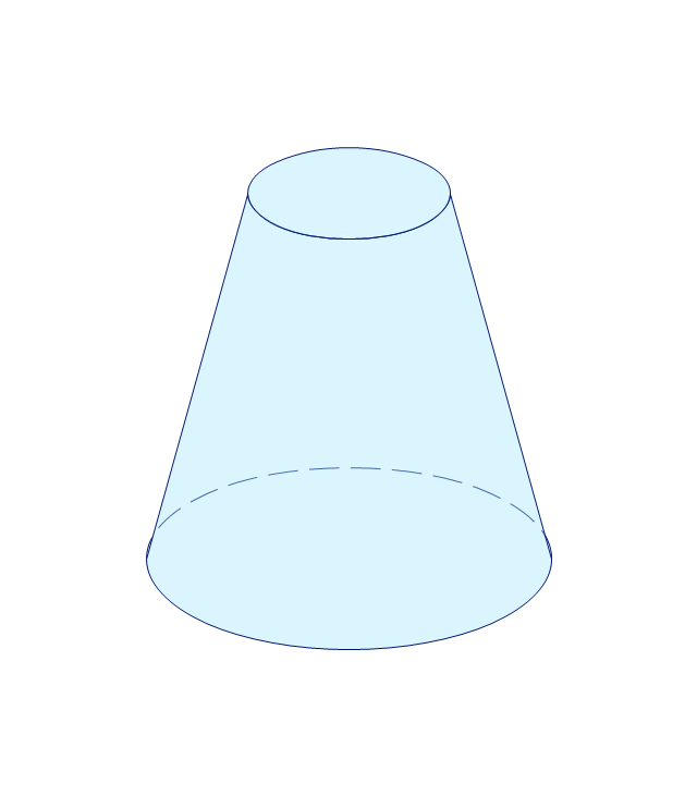
Conical frustum
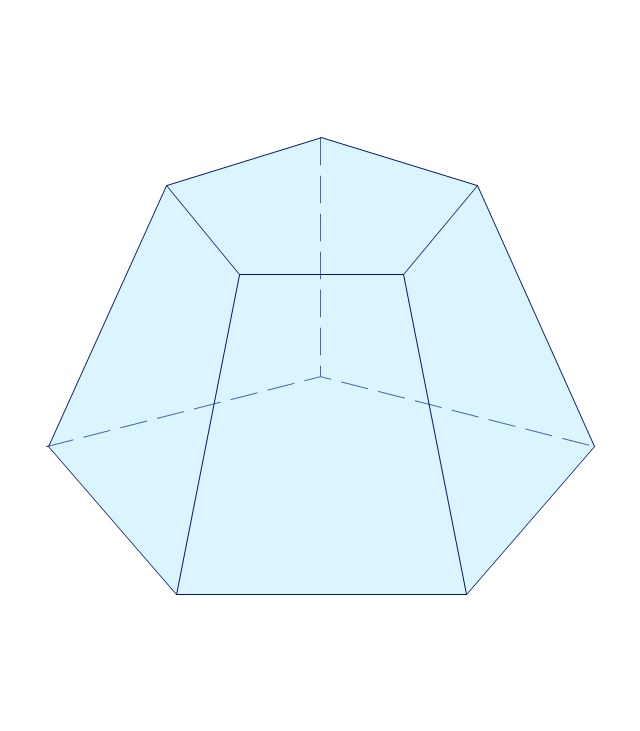
Pentagonal frustum
Tetrahedron
Cone
Cube
Rectangular cuboid
Regular tetrahedron
Square pyramid
Square frustum
Octahedron
Pentagonal pyramid
Irregular polyhedron
Icosahedron
Dodecahedron
Hemisphere
The vector stencils library "Dimensioning and tolerancing" contains 45 symbols of geometric dimensions and mechanical tolerances, geometric symbols, callouts, and text boxes and inserts.
Use these geometric dimensioning and tolerancing (GD&T) shapes to create annotated mechanical drawings in the ConceptDraw PRO diagramming and vector drawing software extended with the Mechanical Engineering solution from the Engineering area of ConceptDraw Solution Park.
www.conceptdraw.com/ solution-park/ engineering-mechanical
Datum (old)
-dimensioning-and-tolerancing---vector-stencils-library.png--diagram-flowchart-example.png)
Box callout

Datum symbol

Callout

All around callout

Text block

2 datum frame

Simple frame

Basic frame

1 datum frame

3 datum frame

Straightness

Flatness

Line profile

Circularity

Cylindricity

Surface profile

Position

Concentricity

Symmetry

Parallelism

Perpendicularity

Angularity

Material condition

Arc length

Diameter

Counterbore/ spotface

Countersink

Depth

Slope

Conical taper

Statistical tolerance

Datum (new)
-dimensioning-and-tolerancing---vector-stencils-library.png--diagram-flowchart-example.png)
Datum (new) 2
-2-dimensioning-and-tolerancing---vector-stencils-library.png--diagram-flowchart-example.png)
Target point

Target line

Target area (circle)
-dimensioning-and-tolerancing---vector-stencils-library.png--diagram-flowchart-example.png)
Target area (rectangle)
-dimensioning-and-tolerancing---vector-stencils-library.png--diagram-flowchart-example.png)
Total runout

Total runout 2

Circular runout

Circular runout 2

Surface finish

Surface finish, removal process

Surface finish, no process permitted

Basic Flowchart Symbols and Meaning


The vector stencils library "Solid geometry" contains 15 shapes of solid geometric figures.
Use these shapes to draw your geometrical diagrams and illustrations in the ConceptDraw PRO diagramming and vector drawing software extended with the Mathematics solution from the Science and Education area of ConceptDraw Solution Park.
Use these shapes to draw your geometrical diagrams and illustrations in the ConceptDraw PRO diagramming and vector drawing software extended with the Mathematics solution from the Science and Education area of ConceptDraw Solution Park.
Conical frustum
Pentagonal frustum
Tetrahedron
Cone
Cube
Rectangular cuboid
Regular tetrahedron
Square pyramid
Square frustum
Octahedron
Pentagonal pyramid
Irregular polyhedron
Icosahedron
Dodecahedron
Hemisphere
The vector stencils library "Plane geometry" contains 27 plane geometric figures.
Use these shapes to draw your geometrical diagrams and illustrations in the ConceptDraw PRO diagramming and vector drawing software extended with the Mathematics solution from the Science and Education area of ConceptDraw Solution Park.
Use these shapes to draw your geometrical diagrams and illustrations in the ConceptDraw PRO diagramming and vector drawing software extended with the Mathematics solution from the Science and Education area of ConceptDraw Solution Park.
Circular sector
Right triangle
Rectangle
Square
Pentagon
Isosceles trapezium
Parallelogram
Trapezium
Three-pointed star
Four-pointed star
Five-pointed star
Six-pointed star
Seven-pointed star
Eight-pointed star
Triangle
Equilateral triangle
Right triangle 2
Right triangle, angle box
Right triangle 3
Hexagon
Regular hexagon
Regular pentagon
Regular heptagon
Regular octagon
Rhombus
Circle
Ellipse
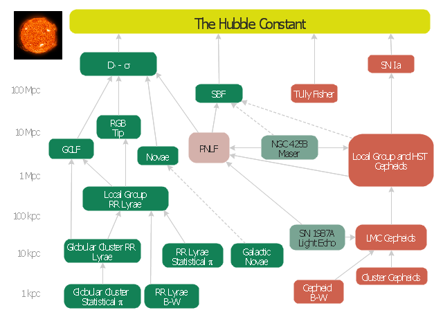
This astronomic diagram example was redesigned from the Wikimedia Commons file: Extragalactic distance ladder.JPG.
[commons.wikimedia.org/ wiki/ File:Extragalactic_ distance_ ladder.JPG]
Red boxes: Technique applicable to star-forming galaxies.
Green boxes: Technique applicable to Population II galaxies.
Cyan boxes: Geometric distance technique.
Pink box: The planetary nebula luminosity function technique is applicable to all populations of the Virgo Supercluster.
Solid lines: Well calibrated ladder step.
Dashed lines: Uncertain calibration ladder step.
"The cosmic distance ladder (also known as the extragalactic distance scale) is the succession of methods by which astronomers determine the distances to celestial objects. A real direct distance measurement of an astronomical object is possible only for those objects that are "close enough" (within about a thousand parsecs) to Earth. The techniques for determining distances to more distant objects are all based on various measured correlations between methods that work at close distances with methods that work at larger distances. Several methods rely on a standard candle, which is an astronomical object that has a known luminosity.
The ladder analogy arises because no one technique can measure distances at all ranges encountered in astronomy. Instead, one method can be used to measure nearby distances, a second can be used to measure nearby to intermediate distances, and so on. Each rung of the ladder provides information that can be used to determine the distances at the next higher rung." [Cosmic distance ladder. Wikipedia]
The astronomy diagram sample "Extragalactic distance ladder" was created using the ConceptDraw PRO diagramming and vector drawing software extended with the Astronomy solution from the Science and Education area of ConceptDraw Solution Park.
Cosmic distance ladder
The vector stencils library "Dimensioning and tolerancing" contains 45 symbols of geometric dimensions and mechanical tolerances, geometric symbols, callouts, and text boxes and inserts.
Use these geometric dimensioning and tolerancing (GD&T) shapes to create annotated mechanical drawings.
"Geometric dimensioning and tolerancing (GD&T) is a system for defining and communicating engineering tolerances. It uses a symbolic language on engineering drawings and computer-generated three-dimensional solid models that explicitly describes nominal geometry and its allowable variation. It tells the manufacturing staff and machines what degree of accuracy and precision is needed on each controlled feature of the part. GD&T is used to define the nominal (theoretically perfect) geometry of parts and assemblies, to define the allowable variation in form and possible size of individual features, and to define the allowable variation between features." [Geometric dimensioning and tolerancing. Wikipedia]
The shapes example "Design elements - Dimensioning and tolerancing" was created using the ConceptDraw PRO diagramming and vector drawing software extended with the Mechanical Engineering solution from the ConceptDraw Solution Park.
Dimensioning and tolerancing symbols

The vector stencils library "Solid geometry" contains 15 shapes of solid geometric figures.
"In mathematics, solid geometry was the traditional name for the geometry of three-dimensional Euclidean space - for practical purposes the kind of space we live in. It was developed following the development of plane geometry. Stereometry deals with the measurements of volumes of various solid figures including cylinder, circular cone, truncated cone, sphere, and prisms.
The Pythagoreans had dealt with the regular solids, but the pyramid, prism, cone and cylinder were not studied until the Platonists. Eudoxus established their measurement, proving the pyramid and cone to have one-third the volume of a prism and cylinder on the same base and of the same height, and was probably the discoverer of a proof that the volume of a sphere is proportional to the cube of its radius." [Solid geometry. Wikipedia]
The shapes example "Design elements - Solid geometry" was created using the ConceptDraw PRO diagramming and vector drawing software extended with the Mathematics solution from the Science and Education area of ConceptDraw Solution Park.
Solid geometrical figures
ERD Symbols and Meanings


ConceptDraw PRO: Able to Leap Tall Buildings in a Single Bound

Cisco Network Topology. Cisco icons, shapes, stencils and symbols
")
Mechanical Drawing Symbols

- Design elements - Solid geometry | Mathematics Symbols | Solid ...
- Plane geometry - Vector stencils library
- Solid geometry - Vector stencils library | Mathematics Symbols ...
- Geometric Dimensional Tolerance Symbols
- Geometry Symbols
- Plane geometry - Vector stencils library | Plane geometry - Vector ...
- Solid geometry - Vector stencils library
- Solid geometry - Vector stencils library | Plane geometry - Vector ...
- Geometry Solution
- Geometric Symbol For Me Engg
- Geometry Symbol To All
- Mathematics Symbols | Plane geometry - Vector stencils library ...
- How to Draw Geometric Shapes in ConceptDraw PRO ...
- Plane geometry - Vector stencils library | Geometric Pentagons Png
- Plane geometry - Vector stencils library | Geometric Triangle Png
- Design elements - Dimensioning and tolerancing | Dimensioning ...
- Solid geometry - Vector stencils library
- Plane geometry - Vector stencils library | Mechanics - Vector stencils ...
- Plane geometry - Vector stencils library | Cross-Functional Flowchart ...
- Plane geometry - Vector stencils library | Octagon Pattern