 Network Layout Floor Plans
Network Layout Floor Plans solution extends ConceptDraw DIAGRAM software functionality with powerful tools for quick and efficient documentation the network equipment and displaying its location on the professionally designed Network Layout Floor Plans. Never before creation of Network Layout Floor Plans, Network Communication Plans, Network Topologies Plans and Network Topology Maps was not so easy, convenient and fast as with predesigned templates, samples, examples and comprehensive set of vector design elements included to the Network Layout Floor Plans solution. All listed types of plans will be a good support for the future correct cabling and installation of network equipment.
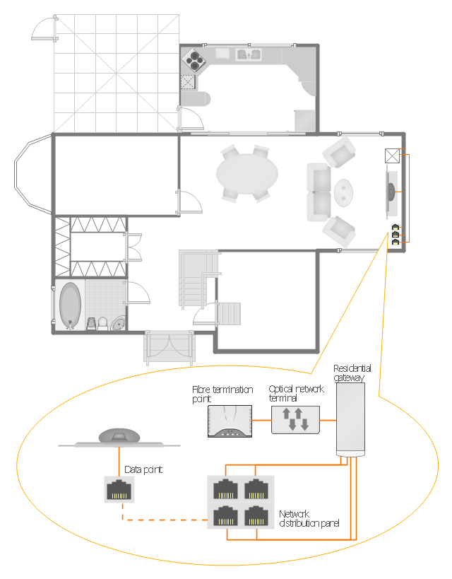
"A home network or home area network (HAN) is a type of local area network that develops from the need to facilitate communication and interoperability among digital devices present inside or within the close vicinity of a home. Devices capable of participating in this network - smart devices such as network printers and handheld mobile computers - often gain enhanced emergent capabilities through their ability to interact. These additional capabilities can then be used to increase the quality of life inside the home in a variety of ways, such as automation of repetitious tasks, increased personal productivity, enhanced home security, and easier access to entertainment." [Home network. Wikipedia]
The HAN equipment layout floorplan example "Home network plan" was created using the ConceptDraw PRO diagramming and vector drawing software extended with the Network Layout Floor Plans solution from the Computer and Networks area of ConceptDraw Solution Park.
The HAN equipment layout floorplan example "Home network plan" was created using the ConceptDraw PRO diagramming and vector drawing software extended with the Network Layout Floor Plans solution from the Computer and Networks area of ConceptDraw Solution Park.
Network Layout
The Network Layout Diagram visually illustrates the arrangement of computers, nodes and other network appliances, such as servers, printers, routers, switches, hubs, and their relationships between each other. The network layout and placement of servers greatly influence on the network security and network performance. Elaboration of robust Network Layout Diagram is especially important when visualizing already existing network in order to understand its complexity; when troubleshooting the network issues; designing, documenting and implementing new network configurations; extending, modifying, or moving an existing network to other location. Through the careful thinking the network plan and designing the clear Network Layout Diagram, you can be confident in result on the stage of network implementation and to solve faster the problems appearing in network infrastructure. ConceptDraw DIAGRAM enhanced with Computer Network Diagrams solution from Computer and Networks area perfectly suits for drawing Network Layout Diagrams for different network topologies.
- Network Layout Floor Plans | Cisco Network Diagrams | Home ...
- Network Layout Floor Plans | Home Networking | Network Mapper ...
- Network Layout Floor Plans | Home area networks (HAN). Computer ...
- Network Layout | Network Layout Floor Plans | Cisco Network ...
- Network Layout Floor Plans | Network Layout | Local area network ...
- Network Layout | Network Layout Floor Plans | Network ...
- Network Layout Floor Plans | Home Networking | Home network ...
- Network Layout Floor Plans | Ethernet local area network layout floor ...
- Network Layout Floor Plans | Office wireless network plan | Network ...
- Network Layout Floor Plans | Design elements - Network layout ...
- Network Layout Floor Plans | Local area network (LAN). Computer ...
- Network Layout Floor Plans | Network Layout | How to Create a ...
- Network Layout Floor Plans | Home Networking | ConceptDraw PRO ...
- Network Layout Floor Plans | Network Layout | Network Components ...
- Network Layout Floor Plans | Network Visualization | Network Layout ...
- Sports bar - Floor plan | Home network plan | Design elements ...
- Network Layout | Network Layout Floor Plans | Network Diagram ...
- Home Networking | Home area networks (HAN). Computer and ...
- Network Layout Floor Plans | Ethernet cable layout | Ethernet local ...
- Network Layout Floor Plans | Network Layout | How to Create a ...

