Tree Network Topology Diagram

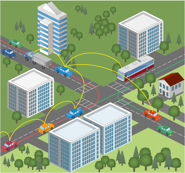
This vehicular network diagram sample was drawn on the base of picture illustrating the post "Intelligent transportation system" from the blog "Technology New Here".
"Intelligent transportation systems are projects that aim to integrate modern communication and information technology into existing transportation management systems in order to optimize vehicle life, fuel efficiency, safety, and traffic in urbanized cities.
The need for intelligent transportation systems stems from the fact that traffic congestion has been increasing all around the world because of increasing population, increasing amount of transportation vehicles and increasing urbanization."
[technologynewhere.wordpress.com/ 2010/ 05/ 12/ intelligent-transportation-system/ ]
The vehicular network diagram example "Intelligent transportation system" was created using the ConceptDraw PRO diagramming and vector drawing software extended with the Vehicular Networking solution from the Computer and Networks area of ConceptDraw Solution Park.
Vehicular network diagram
Used Solutions
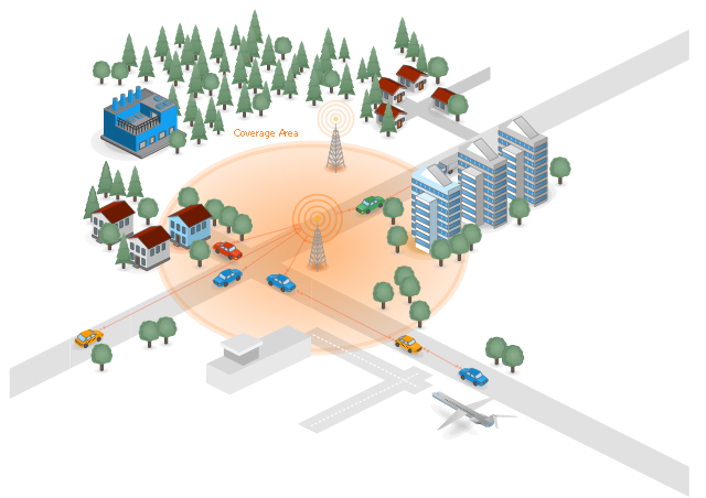
This network diagram sample depicts the cooperative delay-tolerant vehicular communication system.
"Vehicular Communication Systems are an emerging type of networks in which vehicles and roadside units are the communicating nodes; providing each other with information, such as safety warnings and traffic information. As a cooperative approach, vehicular communication systems can be more effective in avoiding accidents and traffic congestions than if each vehicle tries to solve these problems individually.
Generally vehicular networks are considered to contain two types of nodes; vehicles and roadside stations. Both are Dedicated Short Range Communications (DSRC) devices. DSRC works in 5.9 GHz band with bandwidth of 75 MHz and approximate range of 1000m. The network should support both private data communications and public (mainly safety) communications but higher priority is given to public communications. Vehicular communications is usually developed as a part of Intelligent Transport Systems (ITS). ITS seeks to achieve safety and productivity through intelligent transportation which integrates communication between mobile and fixed nodes. To this end ITS heavily relies on wired and wireless communications." [Vehicular communication systems. Wikipedia]
The diagram example "Cooperative vehicular delay-tolerant network" was created using the ConceptDraw PRO diagramming and vector drawing software extended with the Vehicular Networking solution from the Computer and Networks area of ConceptDraw Solution Park.
Vehicular communication system diagram
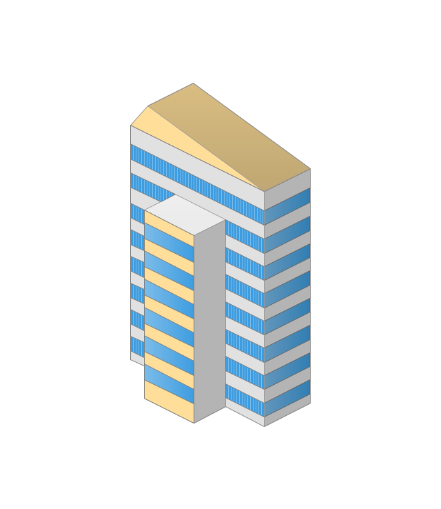
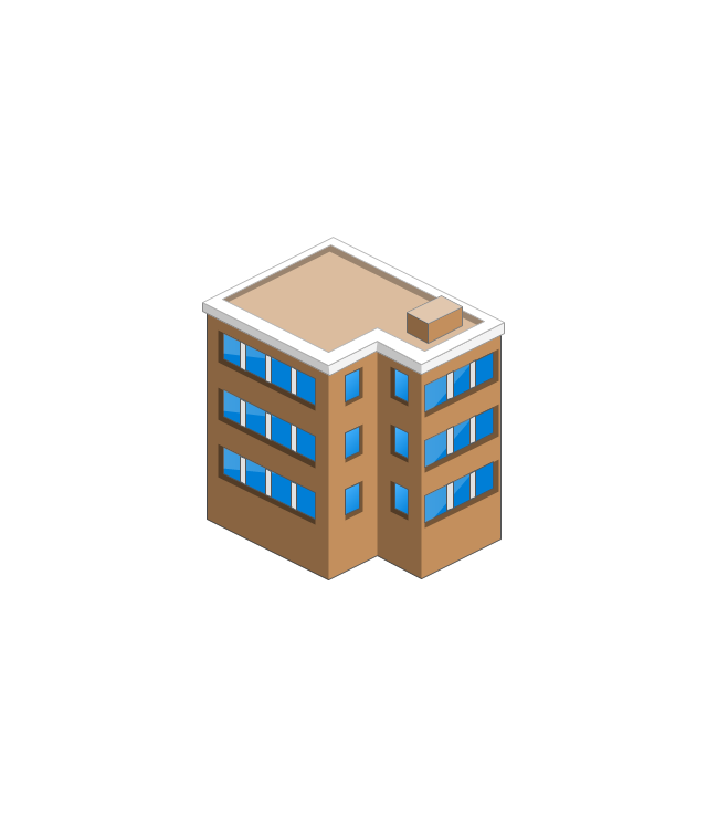
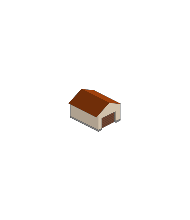
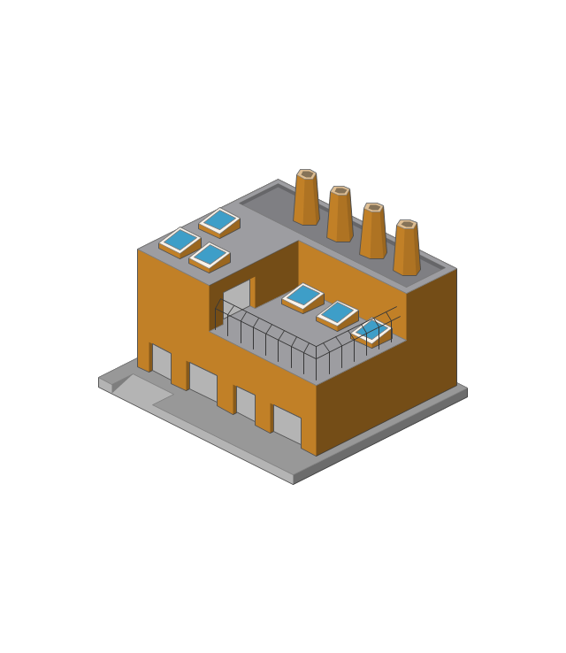
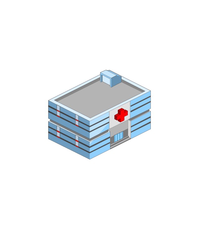
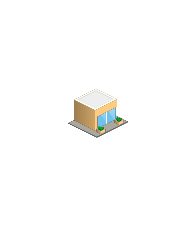
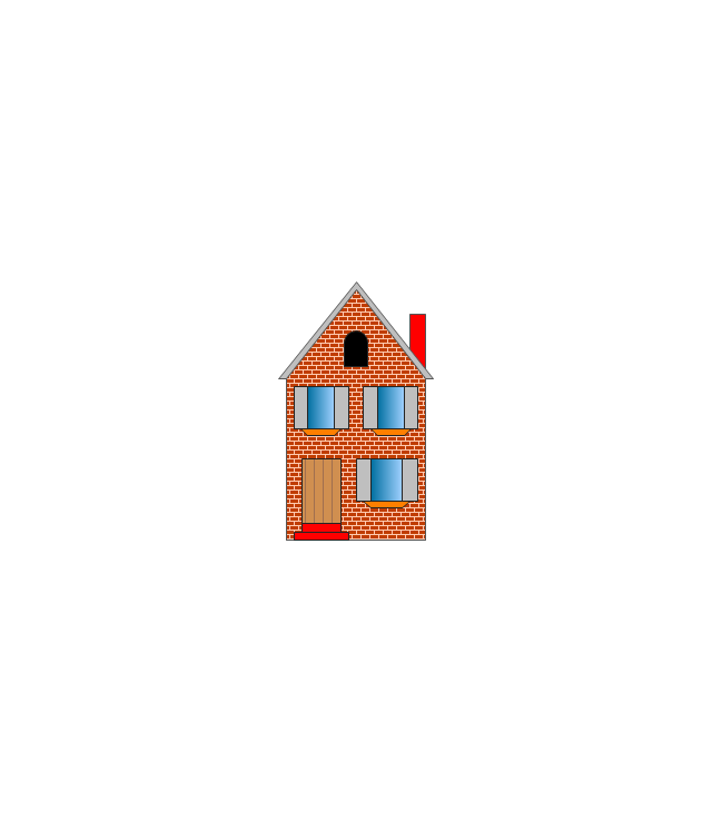
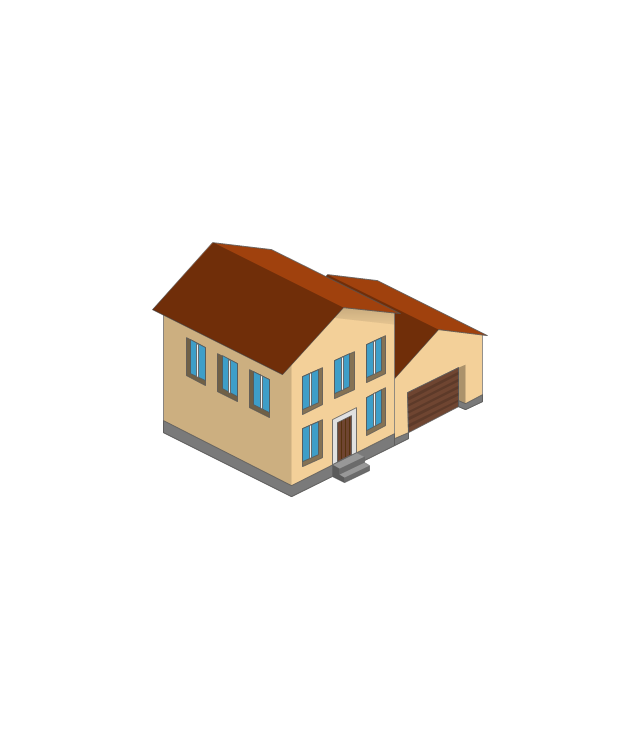
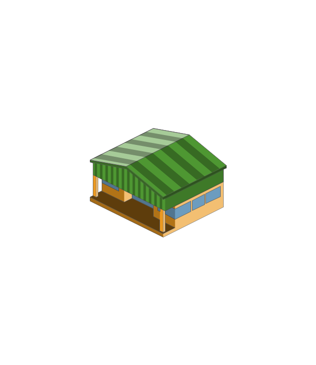
The vector stencils library "Buildings and green spaces" contains 27 clipart images of buildings and green spaces.
"Buildings serve several needs of society – primarily as shelter from weather, security, living space, privacy, to store belongings, and to comfortably live and work." [Building. Wikipedia]
The clip art example "Buildings and green spaces - Vector stencils library" was created using the ConceptDraw PRO diagramming and vector drawing software extended with the Artwork solution from the Illustration area of ConceptDraw Solution Park.
www.conceptdraw.com/ solution-park/ illustrations-artwork
Apartment building
House 1

House 2
House 3

Financial institution

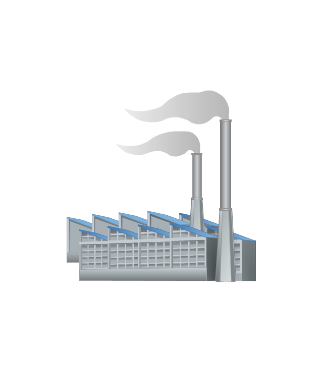
Factory
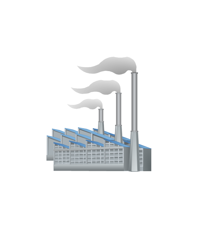
Factory, variable funnels
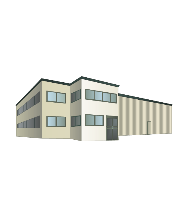
Wholesale warehouse
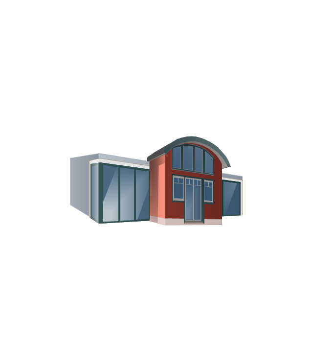
Store
Multi-storey

Tower block
Building
Commercial building

Home

Summer house

Garage
Factory
Hospital
Convenience store
Tree

Fir tree

Town house
Town hall

City

Cottage
Grocery store
Flowerbed

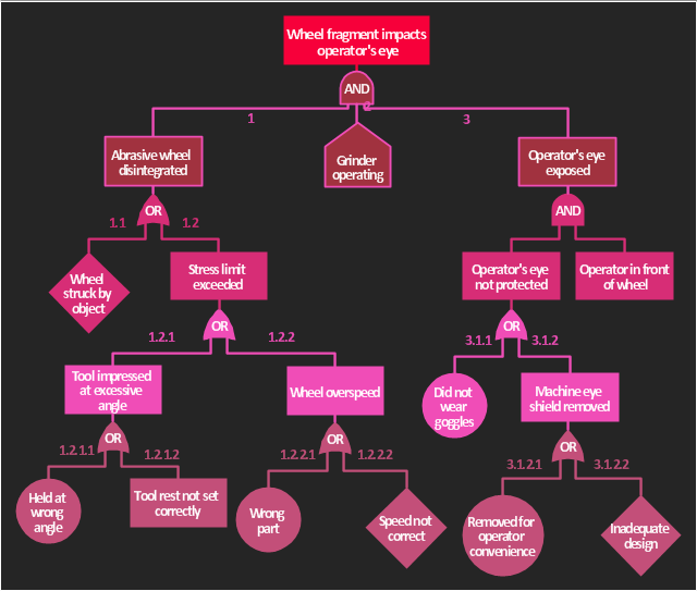
The accident analysis diagram example "Accident analytic tree" was redesigned from the picture 7-14 from the "DOE Workbook. Conducting Accident Investigations. Revision 2."
"Analytic tree analyses are well defined, useful methods that graphically depict, from beginning to end, the events and conditions preceding and immediately following an accident. An analytic tree is a means of organizing information that helps the investigator conduct a deductive analysis of any system (human, equipment, or environmental) to determine critical paths of success and failure. Results from this analysis identify the details and interrelationships that must be considered to prevent the oversights, errors, and omissions that lead to failures. In accident investigations, this type of analysis can consist of both failure paths and success paths, and can lead to neutral, negative, or positive conclusions regarding accident severity.
TIP.
An analytic tree enables the user to:
(1) Systematically identify the possible paths from events to outcome.
(2) Display a graphical record of the analytical process.
(3) Identify management system weaknesses and strengths."
[homer.ornl.gov/ sesa/ corporatesafety/ aip/ docs/ workbook/ Rev2/ chpt7/ chapt7.htm]
The FTA diagram example "Accident analytic tree" was created using the ConceptDraw PRO diagramming and vector drawing software extended with the Fault Tree Analysis Diagrams solution from the Engineering area of ConceptDraw Solution Park.
FTA diagram
Building Drawing Design Element Site Plan


 Site Plans
Vivid and enticing plan is the starting point in landscape design and site plan design, it reflects the main design idea and gives instantly a vision of the end result after implementation of this plan. Moreover site plan, architectural plan, detailed engineering documents and landscape sketches are obligatory when designing large projects of single and multi-floor buildings.
Building Drawing Software for Design Site Plan

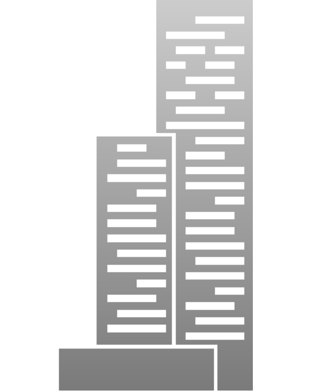
The vector stencils library "Landmarks" contains 69 landmark symbols of buildings, waterways, scale and directional indicators for labeling transportation and directional maps, road and route maps, street and transit maps, locator and tourist maps.
The pictograms example "Landmarks - Vector stencils library" was created using the ConceptDraw PRO diagramming and vector drawing software extended with the Directional Maps solution from the Maps area of ConceptDraw Solution Park.
The pictograms example "Landmarks - Vector stencils library" was created using the ConceptDraw PRO diagramming and vector drawing software extended with the Directional Maps solution from the Maps area of ConceptDraw Solution Park.
Viewpoint

North arrow
North arrow
Building

Building

Town house
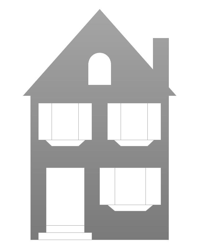
Suburban home

Skyscraper
Town hall

Public house

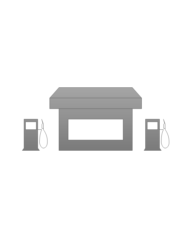
Petrol station
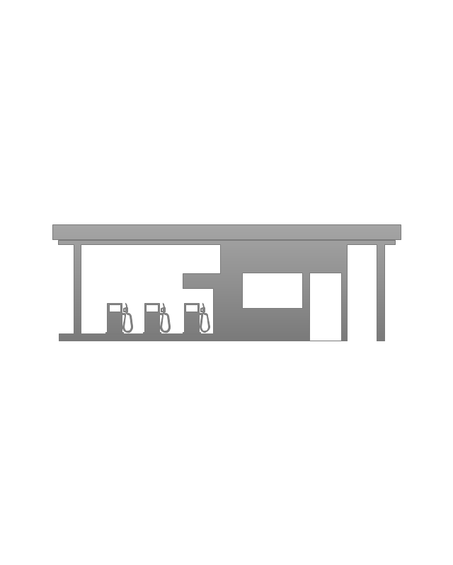
Gas station
Factory

School

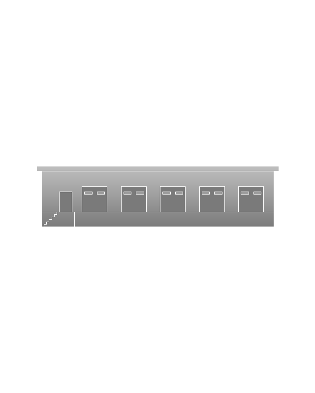
Warehouse
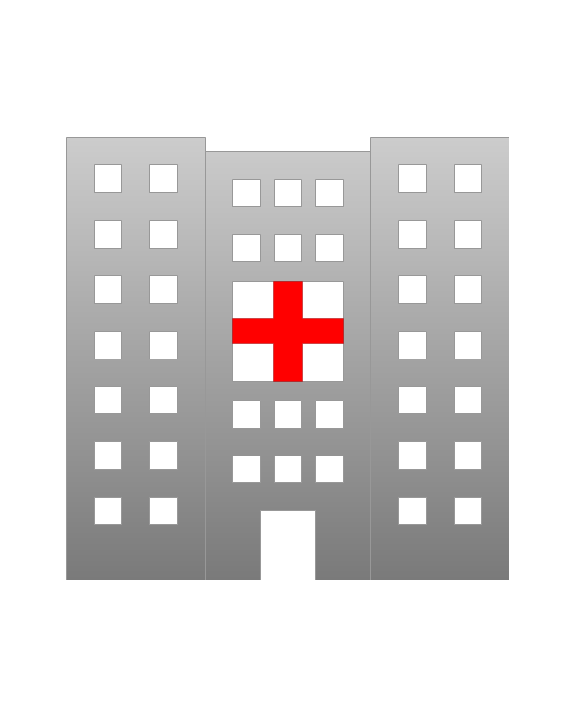
Hospital
Fire station

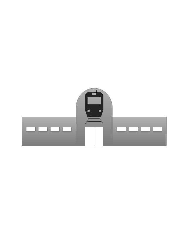
Train station
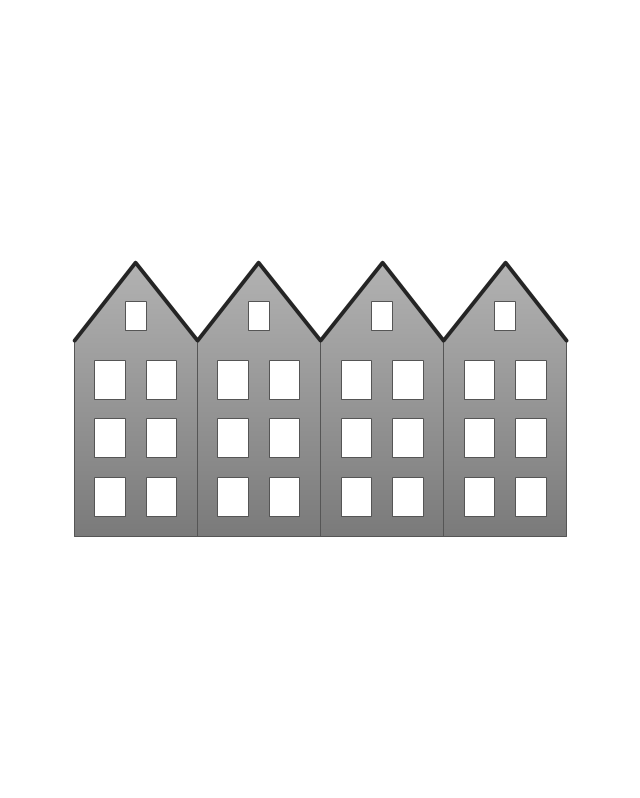
Condos
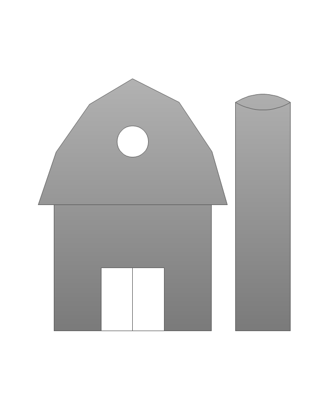
Barn
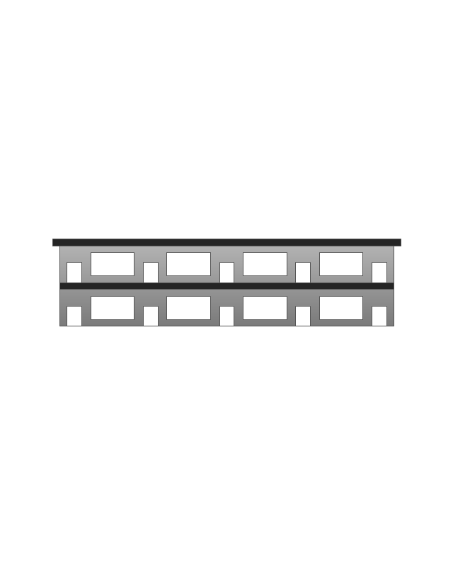
Motel
Convenience store

Shopping centre

City

Church
Cathedral

National tail train station

Train railway

Bus stop

Tramlink

Marina / Ferry dock

Car ferry

Stop light
Airport

Airport

Underground / Subway / Metro

Taxi

Bicycle parking

Parking

Fuel / Gas / Petrol

Police

Hospital

Wheelchair access

First aid

Telephone

Post office

Landmarks and museums

University

Shopping

Refreshments / Public House

Restrooms / Toilets

Park

Zoo

Information center

Stadium 1
Stadium 2
Park

Tree

Fir-tree

Ocean

Lake

River

Angled river

Forked river

Curved river

Curved river

Flexible river

Bridge

Scale
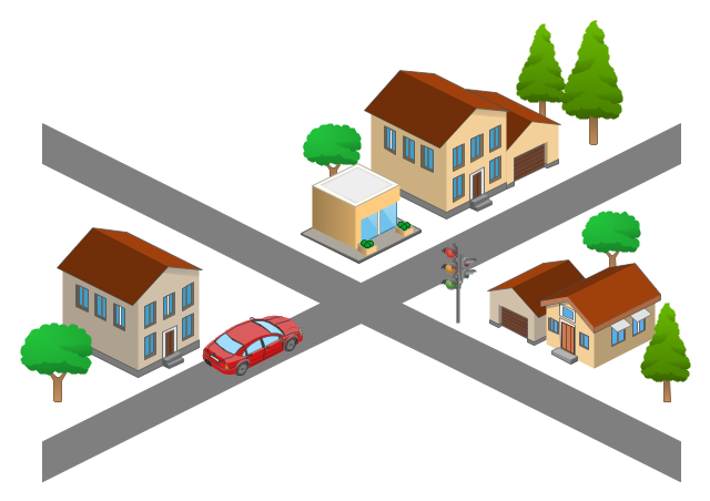
Use this template for creating the 3D pictorial road maps, directional maps, location plans, site plans, transit maps, route maps.
"Road maps can ... vary in complexity, from a simple schematic map used to show how to get to a single specific destination (such as a business), to a complex electronic map, which may layer together many different types of maps and information" [Road map. Wikipedia]
This template for the ConceptDraw PRO diagramming and vector drawing software is included in the Directional Maps solution from the Maps area of ConceptDraw Solution Park.
3D pictorial road map template
- Tree
- Road Map Suburbs And Houses Drawing
- House On Map Route
- Tree Ropad Drawing
- Drawing Communication Of House Car And Road
- Intelligent transportation system | Fault Tree Analysis Diagrams ...
- How To use Appliances Symbols for Building Plan | Building ...
- Draw And Label Road Traffic Sign
- Template Visio Road Traffic Plan
- Cartoon 3d Road With Houses