The vector stencils library "Shipping and receiving" contains 18 symbols of industrial shipping and receiving equipment.
Use the design elements library "Shipping and receiving" to draw factory warehouse equipment layout plans, floor plans of shipping and receiving centers with equipment for hauling, transporting, and distributing manufactured goods, freight, cargo, and stock from plants and industrial facilities using the ConceptDraw PRO diagramming and vector drawing software.
"Freight transport, or shipping, is a key in the value chain in manufacturing.
While all modes of transport are used for cargo transport, there is high differentiation between the nature of the cargo transport, in which mode is chosen.
Logistics refers to the entire process of transferring products from producer to consumer, including storage, transport, transshipment, warehousing, material-handling and packaging, with associated exchange of information.
Containerization, with the standardization of ISO containers on all vehicles and at all ports, has revolutionized international and domestic trade, offering huge reduction in transshipment costs. Traditionally, all cargo had to be manually loaded and unloaded into the haul of any ship or car; containerization allows for automated handling and transfer between modes, and the standardized sizes allow for gains in economy of scale in vehicle operation." [Transport. Freight.
Wikipedia]
This shapes library "Shipping and receiving" is included in the Plant Layout Plans solution from the Building Plans area of ConceptDraw Solution Park.
The vector stencils library "Network layout floorplan" contain 34 symbol icons for drawing computer network floor plans, communication equipment layouts, and structured cabling diagrams.
"Structured cabling is building or campus telecommunications cabling infrastructure that consists of a number of standardized smaller elements (hence structured) called subsystems. ...
Structured cabling design and installation is governed by a set of standards that specify wiring data centers, offices, and apartment buildings for data or voice communications using various kinds of cable, most commonly category 5e (CAT-5e), category 6 (CAT-6), and fibre optic cabling and modular connectors. These standards define how to lay the cabling in various topologies in order to meet the needs of the customer, typically using a central patch panel (which is normally 19 inch rack-mounted), from where each modular connection can be used as needed. Each outlet is then patched into a network switch (normally also rack-mounted) for network use or into an IP or PBX (private branch exchange) telephone system patch panel." [Structured cabling. Wikipedia]
The design elements example "Network layout floorplan - Vector stencils library" was created using the ConceptDraw PRO diagramming and vector drawing software extended with the Network Layout Floor Plans solution from the Computer and Networks area of ConceptDraw Solution Park.
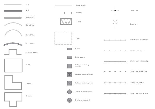
The design elements library Walls, shell and structure contains 29 symbols of structural elements: walls, rooms, windows, doors, pillars.
Use the vector stencils library Walls, shell and structure to draw the floor plans and other architectural drawings, blueprints, home and building interior design, space layout plans, construction and house framing diagrams using the ConceptDraw PRO diagramming and vector drawing software.
"A wall is a horizontal structure, usually solid, that defines and sometimes protects an area. Most commonly, a wall delineates a building and supports its superstructure, separates space in buildings into sections, or protects or delineates a space in the open air. There are three principal types of structural walls: building walls, exterior boundary walls, and retaining walls.
Building walls have one main purpose: to support roofs and ceilings. Such walls most often have three or more separate components. In today's construction, a building wall will usually have the structural elements (such as 2×4 studs in a house wall), insulation, and finish elements or surface (such as drywall or panelling). In addition, the wall may house various types of electrical wiring or plumbing. Electrical outlets are usually mounted in walls.
Building walls frequently become works of art externally and internally, such as when featuring mosaic work or when murals are painted on them; or as design foci when they exhibit textures or painted finishes for effect.
In architecture and civil engineering, the term curtain wall refers to the facade of a building which is not load-bearing but functions as decoration, finish, front, face, or history preservation." [Wall. Wikipedia]
This shapes library Walls, shell and structure is provided by the Floor Plans solution from the Building Plans area of ConceptDraw Solution Park.
HelpDesk
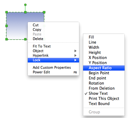
How to Resize Objects Disproportionately in ConceptDraw PRO
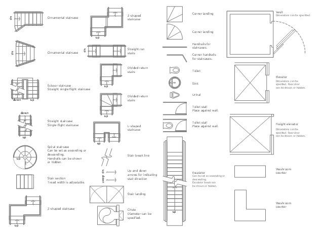
ConceptDraw PRO gives you possibility to freely move, re-size, and rotate objects. You can make them proportionally larger or smaller, as well as re-size objects to make them longer or shorter in only one direction.The design elements library Building core contains 80 symbols of stairs, elevators, escalators, restroom fixtures, and a safe.
Use the shapes library Building core to draw the structural diagrams, bathroom layouts, building automation, architectural drawings, and riser diagrams, as well as space plans, store and shopping mall plans, and facility planning, plant layouts using the ConceptDraw PRO diagramming and vector drawing software.
"In architecture and building engineering, a floor plan otherwise known as a Scottish plan is a drawing to scale, showing a view from above, of the relationships between rooms, spaces and other physical features at one level of a structure.
The term may be used in general to describe any drawing showing the physical layout of objects.
A floor plan could show:
Interior walls and hallways;
Restrooms;
Windows and doors;
Appliances such as stoves, refrigerators, water heater etc.;
Interior features such as fireplaces, saunas and whirlpools;
The use of all rooms shall be indicated." [Floor plan. Wikipedia]
The vector stencils library Building core is provided by the Floor Plans solution from the Building Plans area of ConceptDraw Solution Park.
 Floor Plans
Construction, repair and remodeling of the home, flat, office, or any other building or premise begins with the development of detailed building plan and floor plans. Correct and quick visualization of the building ideas is important for further construction of any building.
 Electric and Telecom Plans
This solution extends ConceptDraw PRO software with samples, templates and libraries of vector stencils for drawing the Electric and Telecom Plans.
- Design elements - Doors and windows | Restaurant Floor Plans ...
- Design elements - Alarm and access control | How To Create Home ...
- Design elements - Alarm and access control | Security System Door ...
- How To use Furniture Symbols for Drawing Building Plan | Interior ...
- Design elements - Doors and windows | Design elements - Alarm ...
- Design elements - Lighting | Design elements - Switches | Design ...
- Design elements - Shipping and receiving | Basic Flowchart ...
- Cisco Switches and Hubs. Cisco icons, shapes, stencils and symbols
- Design Element: Basic Network for Network Diagrams | Design ...
- Design elements - Alarm and access control | Design elements ...
- Symbol Of Double Hung Door
- Design elements - Furniture | How To use Furniture Symbols for ...
- Lighting and switch layout | Design elements - Electrical and ...
- Design elements - Doors and windows | Windows Vista graphic user ...
- Design elements - Shipping and receiving | Interior Design Sport ...
- Design elements - Doors and windows | Network Diagramming ...
- How to Draw a Security and Access Floor Plan | How To Draw ...
- Design elements - Doors and windows | Revolving Windows
- Design elements - Doors and windows | Ray tracing diagram for ...
- Windows Symbol For Network


