 HVAC Plans
Use HVAC Plans solution to create professional, clear and vivid HVAC-systems design plans, which represent effectively your HVAC marketing plan ideas, develop plans for modern ventilation units, central air heaters, to display the refrigeration systems for automated buildings control, environmental control, and energy systems.
HelpDesk
How to Create a HVAC Plan
HVAC plans are used to make and maintain systems of a heating and air conditioning. HVAC plan is an important part of bulding planning. It is developed for privat family houses as well as for apartment and public buildings. Making HVAC plans as a part of construction documentation package essential requirement for any building project. Making a plan that shows the location and connection of HVAC equipment involves many different elements that can be managed using ConceptDraw PRO reinforced with HVAC Plans solution. With ConceptDraw PRO you can easily create and communicate HVAC plans of any complexity.Create Block Diagram
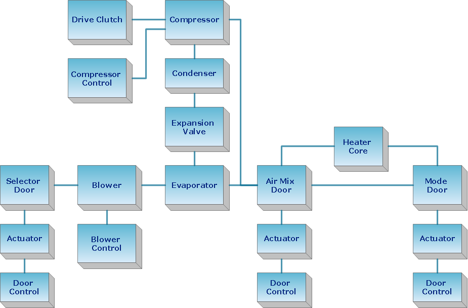
Block diagrams solution extends ConceptDraw PRO software with templates, samples and libraries of vector stencils for creating the block diagram. Create block diagrams, electrical circuit diagrams, schematics, and more in minutes with ConceptDraw PRO.
 Line Graphs
How to draw a Line Graph with ease? The Line Graphs solution extends the capabilities of ConceptDraw PRO v10 with professionally designed templates, samples, and a library of vector stencils for drawing perfect Line Graphs.
 Basic Line Graphs
This solution extends the capabilities of ConceptDraw PRO v10.3.0 (or later) with templates, samples and a library of vector stencils for drawing Line Graphs.
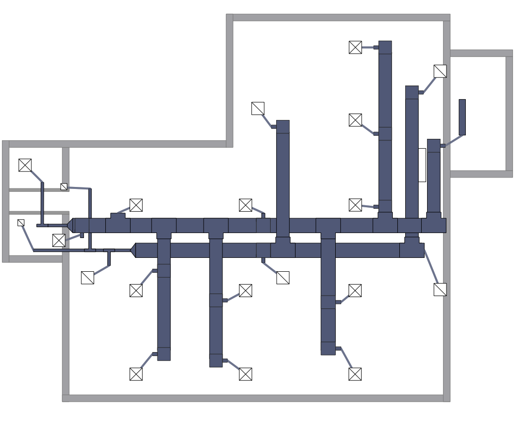
This HVAC floor plan sample shows the ventilation duct system layout.
"Ducts are used in heating, ventilation, and air conditioning (HVAC) to deliver and remove air. The needed airflows include, for example, supply air, return air, and exhaust air. Ducts commonly also deliver ventilation air as part of the supply air. As such, air ducts are one method of ensuring acceptable indoor air quality as well as thermal comfort.
A duct system is also called ductwork. Planning (laying out), sizing, optimizing, detailing, and finding the pressure losses through a duct system is called duct design." [Duct (flow). Wikipedia]
The HVAC floor plan example "Ductwork layout" was created using the ConceptDraw PRO diagramming and vector drawing software extended with the HVAC Plans solution from the Building Plans area of ConceptDraw Solution Park.
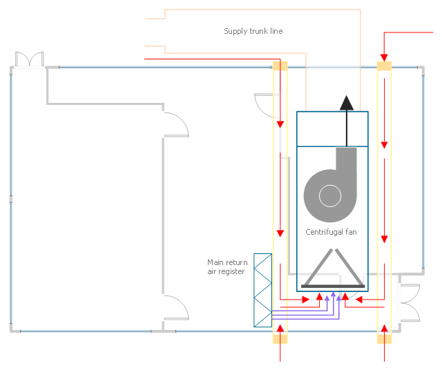
This HVAC plan sample shows the air handler layout on the floor plan.
"An air handler, or air handling unit (often abbreviated to AHU), is a device used to condition and circulate air as part of a heating, ventilating, and air-conditioning (HVAC) system. An air handler is usually a large metal box containing a blower, heating or cooling elements, filter racks or chambers, sound attenuators, and dampers. Air handlers usually connect to a ductwork ventilation system that distributes the conditioned air through the building and returns it to the AHU. Sometimes AHUs discharge (supply) and admit (return) air directly to and from the space served without ductwork.
Small air handlers, for local use, are called terminal units, and may only include an air filter, coil, and blower; these simple terminal units are called blower coils or fan coil units. A larger air handler that conditions 100% outside air, and no recirculated air, is known as a makeup air unit (MAU). An air handler designed for outdoor use, typically on roofs, is known as a packaged unit (PU) or rooftop unit (RTU)." [Air handler. Wikipedia]
The floor plan example "Air handler - HVAC plan" was created using the ConceptDraw PRO diagramming and vector drawing software extended with the HVAC Plans solution from the Building Plans area of ConceptDraw Solution Park.
 Fishbone Diagram
Fishbone Diagrams solution extends ConceptDraw PRO software with templates, samples and library of vector stencils for drawing the Ishikawa diagrams for cause and effect analysis.
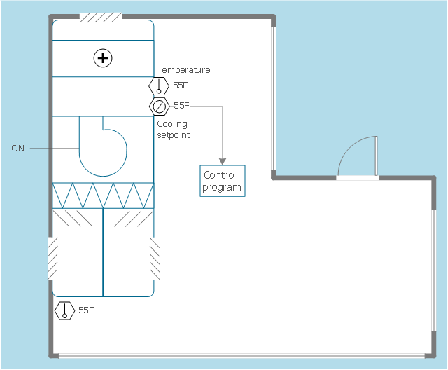
This HVAC floor plan sample illustrates the temperature sensors of air handler digital thermostat control.
"A thermostat is a component of a control system which senses the temperature of a system so that the system's temperature is maintained near a desired setpoint. The thermostat does this by switching heating or cooling devices on or off, or regulating the flow of a heat transfer fluid as needed, to maintain the correct temperature. The name is derived from the Greek words thermos "hot" and statos "a standing".
A thermostat may be a control unit for a heating or cooling system or a component part of a heater or air conditioner. Thermostats can be constructed in many ways and may use a variety of sensors to measure the temperature. The output of the sensor then controls the heating or cooling apparatus. A thermostat may switch on and off at temperatures either side of the setpoint the extent of the difference is known as hysteresis and prevents too frequent switching of the controlled equipment." [Thermostat. Wikipedia]
The HVAC plan example "Digital unit ventilator control" was created using the ConceptDraw PRO diagramming and vector drawing software extended with the HVAC Plans solution from the Building Plans area of ConceptDraw Solution Park.
- Single Line Diagram Of Hvac Water Cooler System
- Hvac Basic Line Diagrams Hd
- Air Conditioner Engineer Drawing
- Images Of Hvac Pipe Line Drawing
- Hvac One Line Diagram
- How To Draw Building Plans | HVAC Plans | Building Drawing ...
- HVAC Plans | RCP - HVAC layout | How to Create a HVAC Plan | Hvac
- HVAC Plans | ConceptDraw Solution Park | Building Drawing ...
- How To Draw Hvac Single Line Diagram
- HVAC Plans
- Aerospace and Transport | HVAC Plans | Aircraft examples ...
- HVAC Plans | How To use House Electrical Plan Software | Building ...
- Air Conditioner Symbol In Drawing
- Hvac Duct Design Example
- Hvac Pipe Line Flow Chart
- Architectur Simlpe Line Plan Of Bank
- HVAC Plans | Building Drawing Software for Designing Plumbing ...
- Draw Fishbone Diagram on MAC Software | HVAC Plans | Pyramid ...
- HVAC Plans | How to Create a HVAC Plan | HVAC Marketing Plan ...
- Percentage Pie Chart. Pie Chart Examples | HVAC Plans | Fishbone ...


