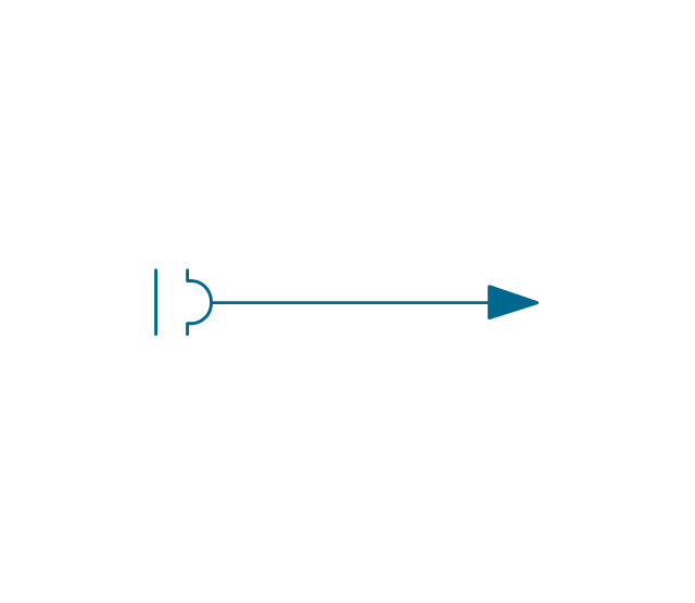
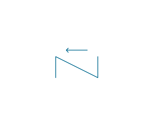
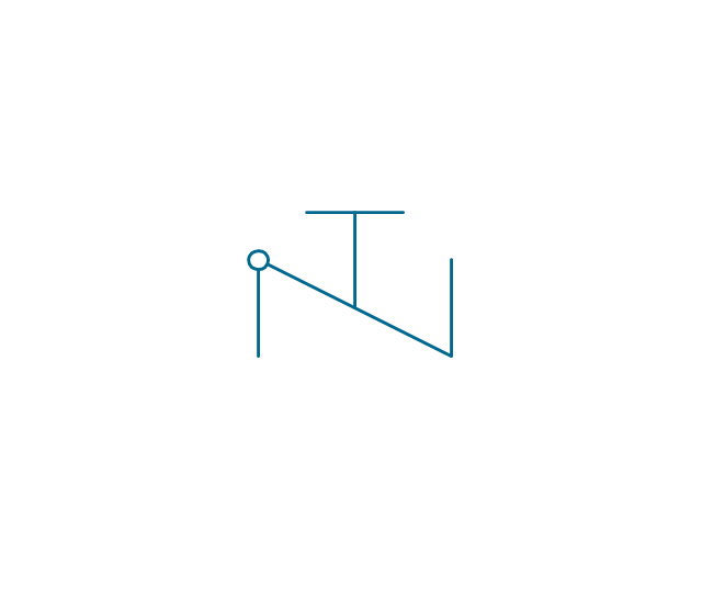
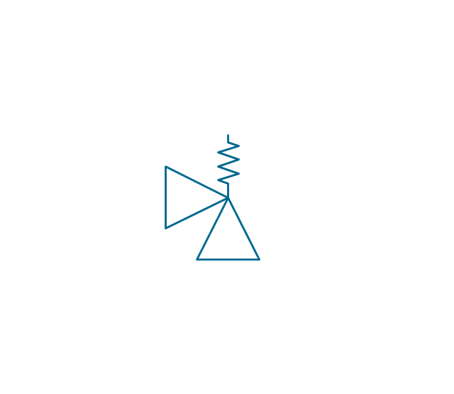
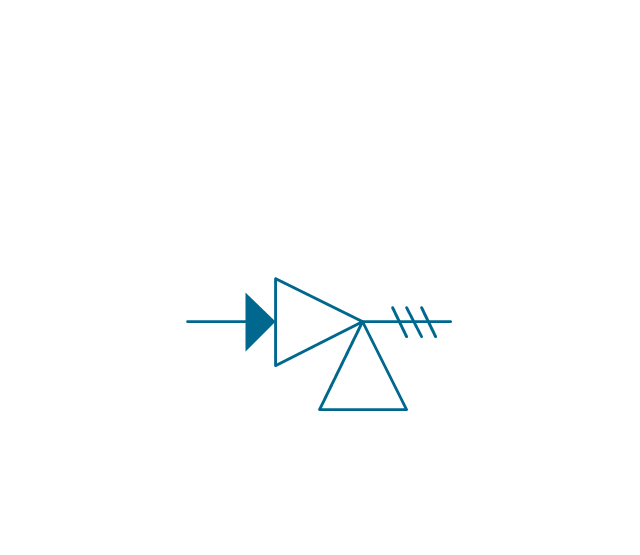
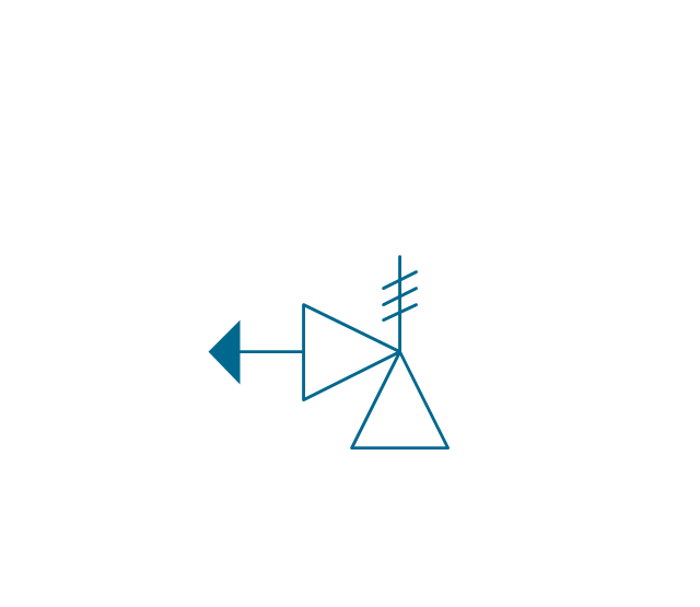
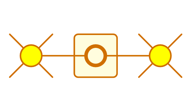
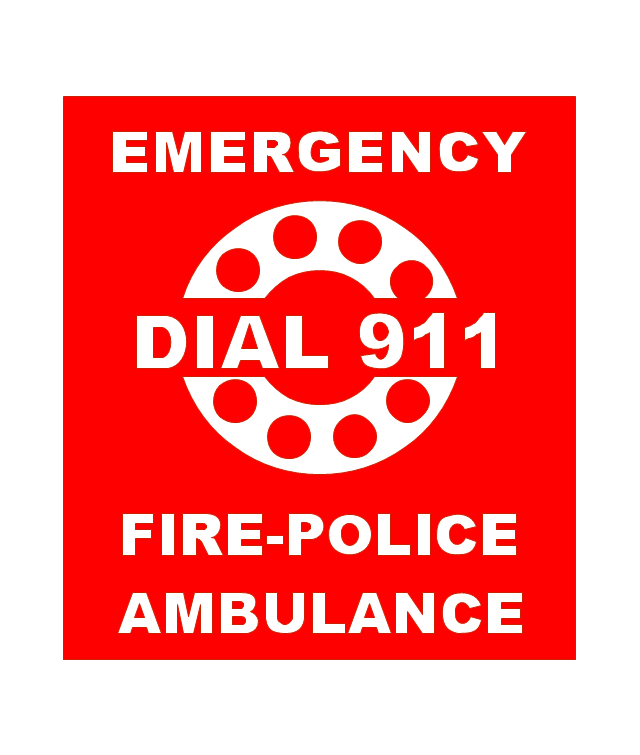
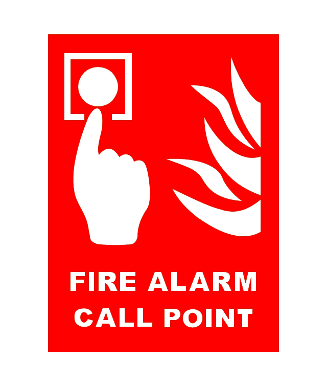
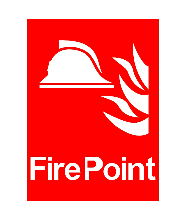
The vector stencils library "Fire and emergency planning" contains 52 symbols of firefighting equipment.
Use these shapes for drawing fire and emergency floor plans, equipment layouts, and evacuation schemes in the ConceptDraw PRO diagramming and vector drawing software extended with the Fire and Emergency Plans solution from the Building Plans area of ConceptDraw Solution Park.
www.conceptdraw.com/ solution-park/ building-fire-emergency-plans
The vector stencils libraries "Pipes 1" and "Pipes 2" contain 28 and 48 pipe, tubing and fitting symbols, respectively.
"A fitting is used in pipe plumbing systems to connect straight pipe or tubing sections, to adapt to different sizes or shapes, and for other purposes, such as regulating or measuring fluid flow. The term plumbing is generally used to describe conveyance of water, gas, or liquid waste in ordinary domestic or commercial environments, whereas piping is often used to describe high-performance (e.g. high pressure, high flow, high temperature, hazardous materials) conveyance of fluids in specialized applications. The term tubing is sometimes used for lighter-weight piping, especially types that are flexible enough to be supplied in coiled form.
Fittings (especially uncommon types) require money, time, materials, and tools to install, so they are a non-trivial part of piping and plumbing systems." [Piping and plumbing fitting. Wikipedia]
Use the design elements libraries "Pipes 1" and "Pipes 2" for drawing plumbing and piping building plans, schematic diagrams, blueprints, or technical drawings of waste water disposal systems, hot and cold water supply systems using the ConceptDraw PRO diagramming and vector drawing software.
The shapes libraries "Pipes 1" and "Pipes 2" are contained in the Plumbing and Piping Plans solution from the Building Plans area of ConceptDraw Solution Park.
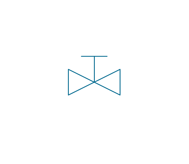
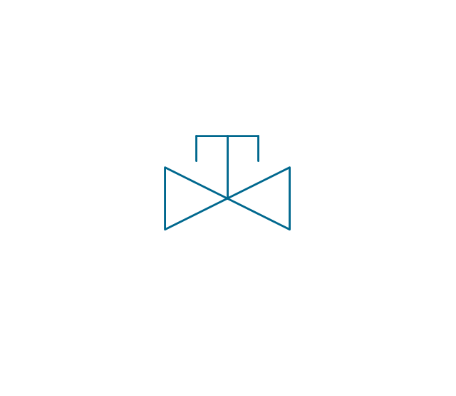
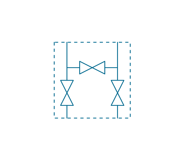
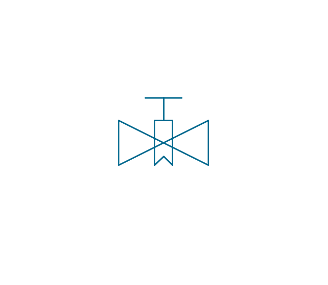
The vector stencils library "Valves and fittings" contains 104 symbols of valve components.
Use these icons for drawing industrial piping systems; process, vacuum, and fluids piping; hydraulics piping; air and gas piping; materials distribution; and liquid transfer systems in the ConceptDraw PRO software extended with the Chemical and Process Engineering solution from the Chemical and Process Engineering area of ConceptDraw Solution Park.
www.conceptdraw.com/ solution-park/ engineering-chemical-process
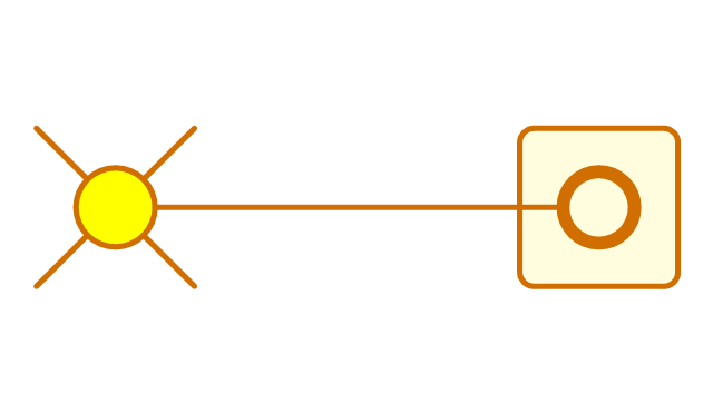
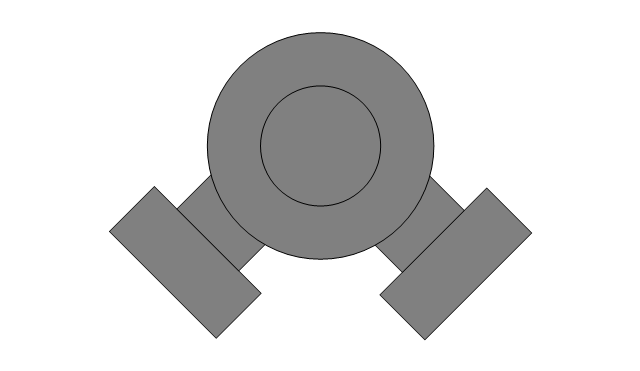
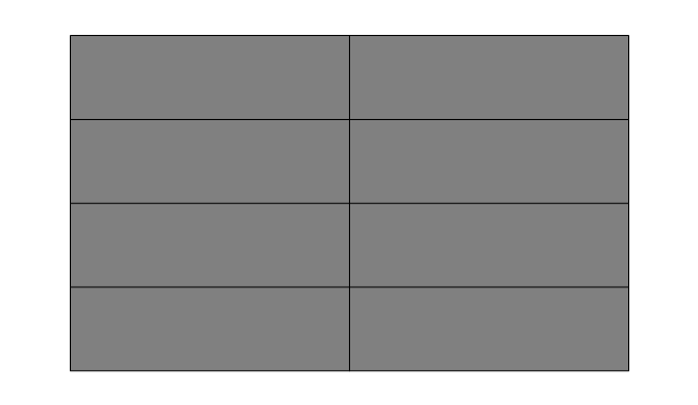
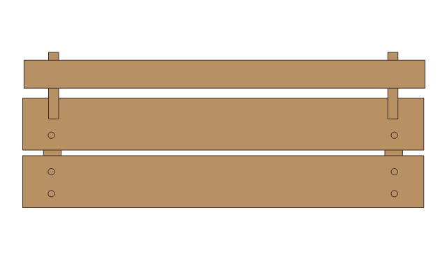
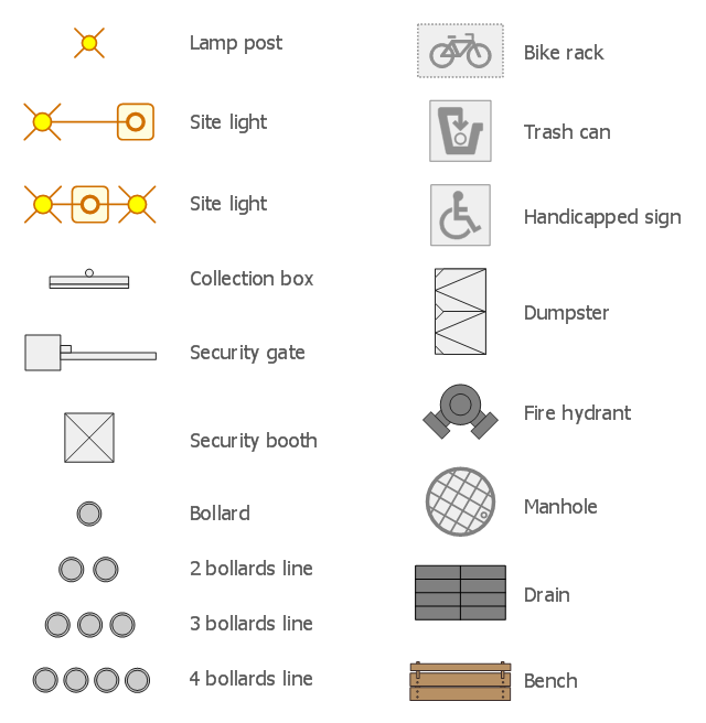
The vector stencils library "Site accessories" contains 18 symbols of vehicle access control equipment (tollbooth, tollgate, parking fees payment box), a handicapped sign, outdoor lighting, and garbage receptacles. Use it to design site plans, parking lots drawings and site management diagrams the ConceptDraw PRO diagramming and vector drawing software extended with the Site Plans solution from the Building Plans area of ConceptDraw Solution Park.
The design elements library Site accessories contains 18 symbols of vehicle access control equipment (tollbooth, tollgate, parking fees payment box), a handicapped sign, outdoor lighting, and garbage receptacles.
"A site plan is an architectural plan, landscape architecture document, and a detailed engineering drawing of proposed improvements to a given lot. A site plan usually shows a building footprint, travelways, parking, drainage facilities, sanitary sewer lines, water lines, trails, lighting, and landscaping and garden elements." [Site plan. Wikipedia]
Use the Site accessories library to design plans, equipment layouts and maps of sites, parking lots, residential and commercial landscapes, parks, yards, plats, outdoor recreational facilities, and irrigation systems using ConceptDraw PRO diagramming and vector drawing software.
The design elements library Site accessories is contained in the Site Plans solution from the Building Plans area of ConceptDraw Solution Park.
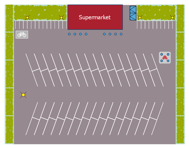
This landscape design sample depicts the supermarket parking site plan.
"Site planning in landscape architecture and architecture refers to the organizational stage of the landscape design process. It involves the organization of land use zoning, access, circulation, privacy, security, shelter, land drainage, and other factors. This is done by arranging the compositional elements of landform, planting, water, buildings and paving in site plans.
Site planning generally begins by assessing a potential site for development through site analysis. Information about slope, soils, hydrology, vegetation, parcel ownership, orientation, etc. are assessed and mapped. By determining areas that are poor for development (such as floodplain or steep slopes) and better for development, the planner or architect can assess optimal location and design a structure that works within this space." [Site planning. Wikipedia]
The site plan example "Supermarket parking" was created using the ConceptDraw PRO diagramming and vector drawing software extended with the Site Plans solution from the Building Plans area of ConceptDraw Solution Park.
- Design elements - Site accessories | Fire Hydrant Symbol ...
- Mechanical Drawing Symbols | Interior Design Piping Plan - Design ...
- Mechanical Drawing Symbols | Design elements - Bearings ...
- Fire Hydrant Symbol On Plans
- Chemical Industries Valve Symbol
- Fire Hydrant Symbol Box With An Arrow
- Fire Hydrant Point Symbol In Autocad
- Mechanical Drawing Symbols | Mechanical Engineering | Interior ...
- Welding symbols | Interior Design Piping Plan - Design Elements ...
- Mechanical Drawing Symbols | Pneumatic 5-ported 3-position valve ...
- Fire Hydrant Symbol
- Mechanical Drawing Symbols | Welding symbols | Elements location ...
- Mechanical Engineering | Mechanical Drawing Symbols | Interior ...
- Backflow Preventer Symbol
- Architectural Plan Of A Fire Hydrant
- Parking For Trucks Plan Symbol
- Mechanical Drawing Symbols | Hydraulic pumps and motors ...
- Mechanical Drawing Symbols | Pneumatic 5-ported 3-position valve ...
- Lighting System Technical Drawing
- Interior Design Piping Plan - Design Elements | Mechanical Drawing ...



























.png--diagram-flowchart-example.png)

