 Plant Layout Plans
Plant Layout Plans solution can be used for power plant design and plant layout design, for making the needed building plant plans and plant layouts looking professionally good. Having the newest plant layout software, the plant design solutions and in particular the ConceptDraw’s Plant Layout Plans solution, including the pre-made templates, examples of the plant layout plans, and the stencil libraries with the design elements, the architects, electricians, interior designers, builders, telecommunications managers, plant design engineers, and other technicians can use them to create the professionally looking drawings within only a few minutes.
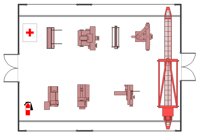
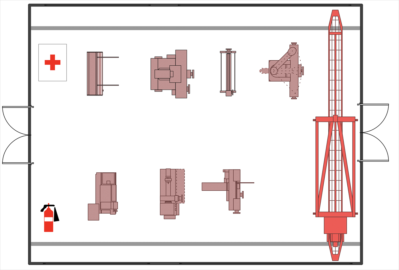
The example "Factory layout floor plan" shows manufacturing machines and equipment in the plant warehouse.
"A factory (previously manufactory) or manufacturing plant is an industrial site, usually consisting of buildings and machinery, or more commonly a complex having several buildings, where workers manufacture goods or operate machines processing one product into another.
Most modern factories have large warehouses or warehouse-like facilities that contain heavy equipment used for assembly line production. Large factories tend to be located with access to multiple modes of transportation, with some having rail, highway and water loading and unloading facilities." [Factory. Wikipedia]
The example "Factory layout floor plan" was created using the ConceptDraw PRO diagramming and vector drawing software extended with the Plant Layout Plans solution from the Building Plans area of ConceptDraw Solution Park.
HelpDesk
How to Create a Plant Layout Design
A plant construction process begins from a plant layout stage - an engineering stage used to design, analyze and finally choose the suitable configurations for a manufacturing plant. Plant Layout issues are core to any enterprise and are challenged in all types of manufacturing process. The sufficiency of layout influences the efficiency of subsequent operations. It is an important background for efficient manufacturing and also has a great deal with many questions. Once the place of the plant has been determined, the next important task before the management of the plant is to plan appropriate layout for the enterprise. Plant layout is used to create the most effective physical arrangement of machinery and equipment, with the plant building in such a manner so as to make quickest and cheapest way from a raw material to the shipment of the completed product Making a plan that shows the location of industrial equipment involves many different elements that can be managed using Con
 Engineering
This solution extends ConceptDraw DIAGRAM.4 with the ability to visualize industrial systems in electronics, electrical, chemical, process, and mechanical engineering.
"A smoke detector is a device that detects smoke, typically as an indicator of fire. Commercial, industrial, and mass residential devices issue a signal to a fire alarm system, while household detectors, known as smoke alarms, generally issue a local audible or visual alarm from the detector itself.
Most smoke detectors work either by optical detection (photoelectric) or by physical process (ionization), while others use both detection methods to increase sensitivity to smoke." [Smoke detector. Wikipedia]
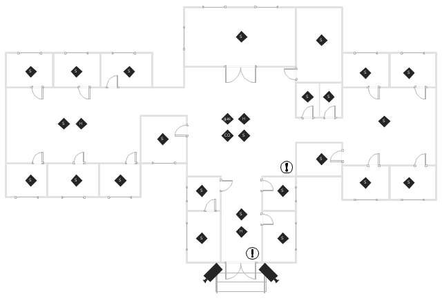
This smoke alarm equipment layout floor plan example was created using the ConceptDraw PRO diagramming and vector drawing software extended with the Security and Access Plans solution from the Building Plans area of ConceptDraw Solution Park.
Network Diagram Software
Network Diagrams are used to visually represent the network architecture, to illustrate the network structure, how the computers and other elements of the network are connected each other using a variety of network symbols, clipart and connection lines. They are incredibly useful on the stages of projecting computer network, of its construction and exploitation. Professionally designed and accurate Network Diagrams are equally convenient for computer engineers and users. You can construct them by hand on the paper or use special network diagramming software, such as ConceptDraw DIAGRAM. Having at disposal the powerful network diagramming tools of Computer Network Diagrams solution included to ConceptDraw Solution Park, you can succeed in drawing various types of Computer Network Diagrams, among them Network Communication Plans, Logical Network Diagrams, Network Topology Diagrams, LAN and WAN Diagrams, Network Floor Plan Layouts, Computer Network System Diagrams, Web-based Network Diagrams, Wireless Network Diagrams, Cisco Network Diagram, and others.
- How to Create a Plant Layout Design | Plant Layout Plans | Plant ...
- Industrial Building Layout Plan
- Factory layout floor plan | Interior Design Machines and Equipment ...
- Industrial Engineering Layout Software
- Industrial Layout Plan
- Plant Layout Plans | Factory layout floor plan | Emergency Plan ...
- Industrial Building Layout Diagrams
- How To use Kitchen Design Software | Plant Layout Plans | CAD ...
- Industrial Floor Plan Design
- How To Make Industrial Layout Plan
- Industrial Electrical Layout Plan
- Store Layout Software | Interior Design Machines and Equipment ...
- Layout Plan Of Industrial Building
- Plant Layout Plans | Process Flowchart | Factory layout floor plan ...
- Plant Layout Plans | Factory layout floor plan | Interior Design ...
- Plant Layout Plans | Warehouse with conveyor system - Floor plan ...
- Industrial Building Basic Layout Plan
- Industrial Furniture
- Plant Layout Plans | CAD Drawing Software for Making Mechanic ...
- Plant Layout Plans | Factory layout floor plan | How to Create a Plant ...


