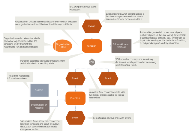
"An Event-driven Process Chain (EPC) is a type of flowchart used for business process modelling. Event-driven Process Chains can be used for configuring an enterprise resource planning (ERP) implementation, and for business process improvement. ...
Businesses use Event-driven Process Chain diagrams to lay out business process work flows, originally in conjunction with SAP R/ 3 modeling, but now more widely. It is used by many companies for modeling, analyzing, and redesigning business processes. The Event-driven Process Chain method was developed within the framework of Architecture of Integrated Information Systems (ARIS). As such it forms the core technique for modeling in ARIS, which serves to link the different views in the so-called control view." [Event-driven process chain. Wikipedia]
The event-driven process chain (EPC) diagram template for the ConceptDraw PRO diagramming and vector drawing software is included in the Event-driven Process Chain Diagrams solution from the Business Processes area of ConceptDraw Solution Park.
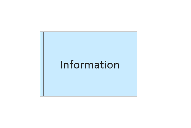
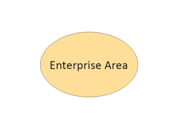
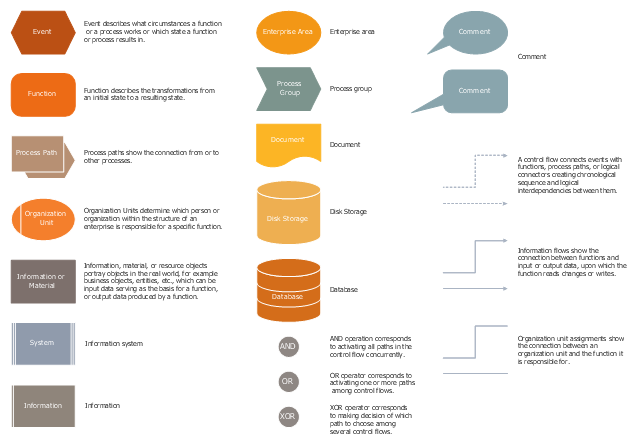
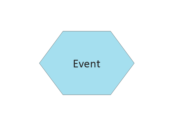
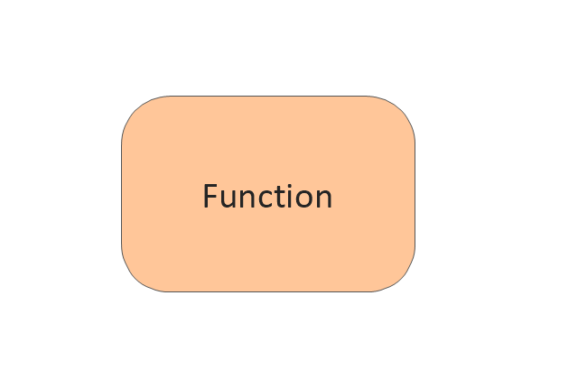
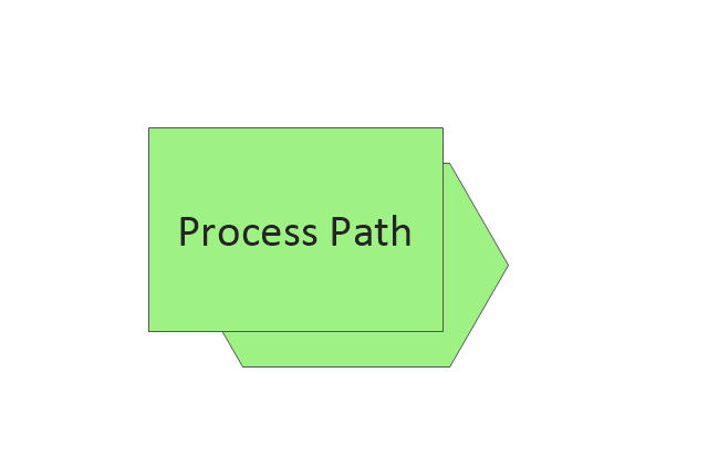
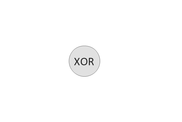
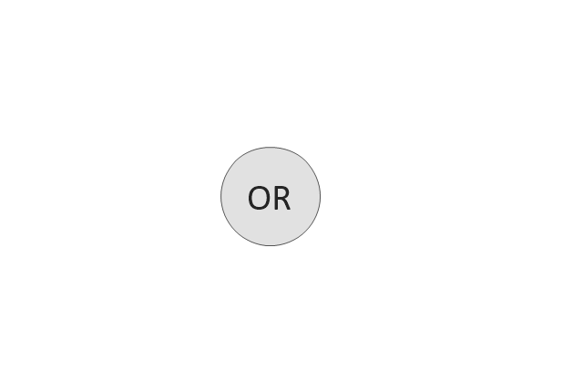
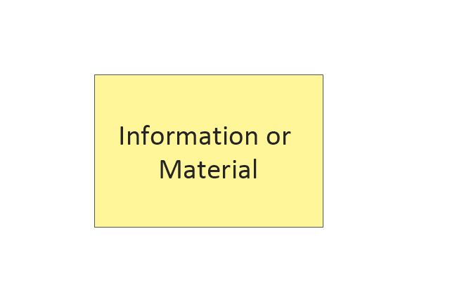
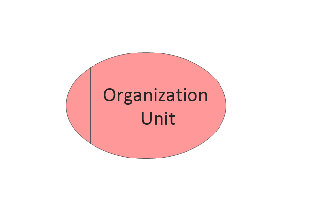
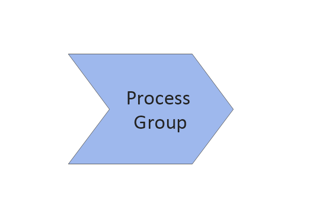
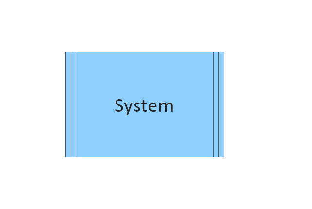
The vector stencils library "EPC diagrams" contains 23 EPC symbols.
Use it for drawing event-driven process chain (EPC) diagrams in the ConceptDraw PRO diagramming and vector drawing software extended with the Event-driven Process Chain Diagrams solution from the Business Processes area of ConceptDraw Solution Park.
www.conceptdraw.com/ solution-park/ business-process-EPC
IDEF1 standard
Use Case Diagrams technology. Using visual graphical objects IDEF1 standard allows to model information interrelations.The vector stencils library "EPC diagrams" contains 23 symbol icons.
Use it to draw the event-driven process chain (EPC) flowcharts for business process modeling (BPM).
"... the elements used in Event-driven Process Chain diagram... :
(1) Event.
(2) Function.
(3) Process Owner.
(4) Organization unit.
(5) Information, material, or resource object.
(6) Logical connector.
(7) Logical relationships: Branch / Merge, Fork / Join, OR.
(8) Control flow.
(9) Information flow.
(10) Organization unit assignment.
(11) Process path. " [Event-driven process chain. Wikipedia]
The EPC symbols example "Design elements - EPC diagram" was created using the ConceptDraw PRO diagramming and vector drawing software extended with the Event-driven Process Chain Diagrams solution from the Business Processes area of ConceptDraw Solution Park.
The vector stencils library "IDEF3 object schematic symbols" contains 12 shapes: objects, links, relations, junctions, connection arrow and line, temporal indeterminacy marker. Use it to design your IDEF3 object schematic diagrams.
"Object Schematics.
IDEF offers a series of building blocks to express detailed object-centered process information; that is, information about how objects of various kinds are transformed into other kinds of things through a process, or how objects of a given kind change states through a process.
- Objects : An object of a certain kind, like a chassis, will be represented simply by a circle containing an appropriate label.
- Object States : A certain kind of object being in a certain state will be represented by a circle with a label that captures the kind itself and a corresponding state, representing thereby the type, or class, of objects that are in that state.
- Object schematics : The construction of complex representations built from kind symbols and object state symbols.
- Transition Schematics : The first and most basic construct is the basic state transition schematic or simply, transition schematic." [IDEF3. Wikipedia]
The shapes example "Design elements - IDEF3 object schematic symbols" was created using the ConceptDraw PRO diagramming and vector drawing software extended with the solution "IDEF Business Process Diagrams" from the area "Business Processes" of ConceptDraw Solution Park.
Databases Access Objects Model with ConceptDraw PRO
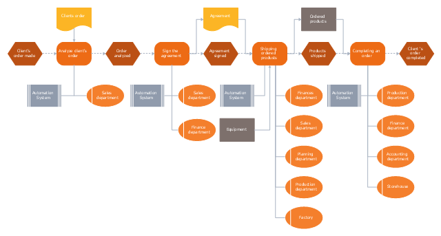
ConceptDraw Basic gives the opportunity of interaction with any ODBC-compatible databases. For this the Database Access Objects Model is provided. All calls to the database are made by certain methods of objects of this model."Order processing is a key element of Order fulfillment. Order processing operations or facilities are commonly called "distribution centers". "Order processing" is the term generally used to describe the process or the work flow associated with the picking, packing and delivery of the packed item(s) to a shipping carrier. The specific "order fulfillment process" or the operational procedures of distribution centers are determined by many factors. Each distribution center has its own unique requirements or priorities. There is no "one size fits all" process that universally provides the most efficient operation." [Order processing. Wikipedia]
The business process modeling (BPM) flowchart example "Order processing - EPC flow chart" was created using the ConceptDraw PRO diagramming and vector drawing software extended with the Event-driven Process Chain Diagrams solution from the Business Processes area of ConceptDraw Solution Park.
The business process modeling (BPM) flowchart example "Order processing - EPC flow chart" was created using the ConceptDraw PRO diagramming and vector drawing software extended with the Event-driven Process Chain Diagrams solution from the Business Processes area of ConceptDraw Solution Park.
"Order processing is a key element of Order fulfillment. Order processing operations or facilities are commonly called "distribution centers". "Order processing" is the term generally used to describe the process or the work flow associated with the picking, packing and delivery of the packed item(s) to a shipping carrier. The specific "order fulfillment process" or the operational procedures of distribution centers are determined by many factors. Each distribution center has its own unique requirements or priorities. There is no "one size fits all" process that universally provides the most efficient operation." [Order processing. Wikipedia]
The business process modeling (BPM) flowchart example "Order processing - EPC flow chart" was created using the ConceptDraw PRO diagramming and vector drawing software extended with the Event-driven Process Chain Diagrams solution from the Business Processes area of ConceptDraw Solution Park.
The business process modeling (BPM) flowchart example "Order processing - EPC flow chart" was created using the ConceptDraw PRO diagramming and vector drawing software extended with the Event-driven Process Chain Diagrams solution from the Business Processes area of ConceptDraw Solution Park.
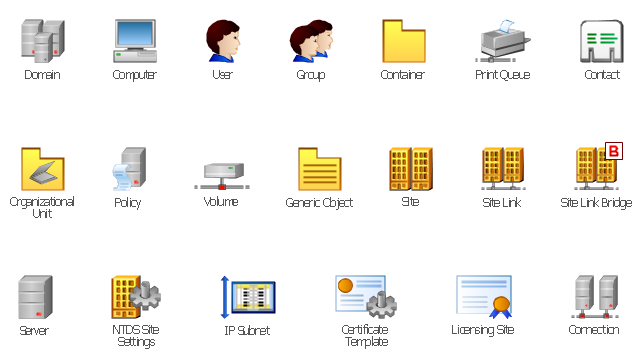
The vector stencils library "Active Directory" contains 20 symbols of Active Directory objects for drawing AD network diagrams. It helps network and system administrators to visualize Microsoft Windows Active Directory structures for network design, installation and maintainance.
"Objects.
An Active Directory structure is an arrangement of information about objects. The objects fall into two broad categories: resources (e.g., printers) and security principals (user or computer accounts and groups). Security principals are assigned unique security identifiers (SIDs).
Each object represents a single entity - whether a user, a computer, a printer, or a group - and its attributes. Certain objects can contain other objects. An object is uniquely identified by its name and has a set of attributes - the characteristics and information that the object represents - defined by a schema, which also determines the kinds of objects that can be stored in Active Directory.
The schema object lets administrators extend or modify the schema when necessary. However, because each schema object is integral to the definition of Active Directory objects, deactivating or changing these objects can fundamentally change or disrupt a deployment. Schema changes automatically propagate throughout the system. Once created, an object can only be deactivated - not deleted. Changing the schema usually requires planning. Sites are implemented as a set of well-connected subnets." [Active Directory. Wikipedia]
The shapes example "Design elements - Active Directory" was created using the ConceptDraw PRO diagramming and vector drawing software extended with the Active Directory Diagrams solution from the Computer and Networks area of ConceptDraw Solution Park.
The vector stencils library "Active Directory" contains 20 symbols of Active Directory elements for drawing AD network diagrams. It helps network and system administrators to visualize Microsoft Windows Active Directory structures for network design, installation and maintainance.
"An Active Directory structure is an arrangement of information about objects. The objects fall into two broad categories: resources (e.g., printers) and security principals (user or computer accounts and groups). Security principals are assigned unique security identifiers (SIDs).
Each object represents a single entity - whether a user, a computer, a printer, or a group - and its attributes. Certain objects can contain other objects. An object is uniquely identified by its name and has a set of attributes - the characteristics and information that the object represents - defined by a schema, which also determines the kinds of objects that can be stored in Active Directory.
The schema object lets administrators extend or modify the schema when necessary. However, because each schema object is integral to the definition of Active Directory objects, deactivating or changing these objects can fundamentally change or disrupt a deployment. Schema changes automatically propagate throughout the system. Once created, an object can only be deactivated - not deleted. Changing the schema usually requires planning. Sites are implemented as a set of well-connected subnets." [Active Directory. Wikipedia]
The AD symbols example "Active Directory - Vector stencils library" was created using the ConceptDraw PRO diagramming and vector drawing software extended with the Active Directory Diagrams solution from the Computer and Networks area of ConceptDraw Solution Park.
www.conceptdraw.com/ solution-park/ active-directory-diagrams
Control and Information Architecture Diagrams (CIAD) with ConceptDraw PRO
One of the three main constituents of any enterprise is the Control and Information Architecture. The rest two are Production facilities and People and Organization.- Information / Material Object
- Information Flow
- And Operator
- Design elements - EPC diagram | Project management life cycle ...
- Data Flow Diagram Model
- Draw Object Daigram For Bank Information System
- Enterprise Area
- Design elements - EPC diagram | Entity Relationship Diagram ...
- Software Development | Information Architecture | What Is ...
- Order processing - EPC flow chart | Credit Card Order Process ...
- Order processing - EPC flow chart | Order processing - Cross ...
- Event-driven Process Chain (EPC) Diagrams | EPC diagram ...
- Event-driven Process Chain (EPC) Diagrams | An Event-driven ...
- Design elements - IDEF3 object schematic symbols | Transition ...
- Sequence Diagrams For Library Information System
- Information Architecture | What Is Information Architecture | Control ...
- Order processing - EPC flow chart
- How to Connect a Live Object to a Text Data Source | How to ...
- Active Directory Diagram | Active Directory structure diagram | How ...



-epc-diagrams---vector-stencils-library.png--diagram-flowchart-example.png)
-epc-diagrams---vector-stencils-library.png--diagram-flowchart-example.png)
-epc-diagrams---vector-stencils-library.png--diagram-flowchart-example.png)
-epc-diagrams---vector-stencils-library.png--diagram-flowchart-example.png)
-epc-diagrams---vector-stencils-library.png--diagram-flowchart-example.png)
-epc-diagrams---vector-stencils-library.png--diagram-flowchart-example.png)
