Interior Design. Machines and Equipment — Design Elements
Drawing your own plant layouts for storage, production, distribution, shipping, transport and receiving the manufactured goods is always easier with help of special software which can make your diagrams look very sophisticated and professional even if you have not much experience in creating such flowcharts. With help of Machines and equipment library available for your use now, you can make incredibly looking smart and structured diagram using the design elements.HelpDesk
How to Create a Plant Layout Design
A plant construction process begins from a plant layout stage - an engineering stage used to design, analyze and finally choose the suitable configurations for a manufacturing plant. Plant Layout issues are core to any enterprise and are challenged in all types of the manufacturing process. The sufficiency of layout influences the efficiency of subsequent operations.It is an important background for efficient manufacturing and also has a great deal with many questions. Once the place of the plant has been determined, the next important task before the management of the plant is to plan appropriate layout for the enterprise.
Plant layout is used to create the most effective physical arrangement of machinery and equipment, with the plant building in such a manner so as to make quickest and cheapest way from raw material to the shipment of the completed product
Making a plan that shows the location of industrial equipment involves many different elements that can be managed using Con
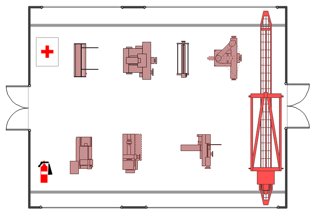
The example "Factory layout floor plan" shows manufacturing machines and equipment in the plant warehouse.
"A factory (previously manufactory) or manufacturing plant is an industrial site, usually consisting of buildings and machinery, or more commonly a complex having several buildings, where workers manufacture goods or operate machines processing one product into another.
Most modern factories have large warehouses or warehouse-like facilities that contain heavy equipment used for assembly line production. Large factories tend to be located with access to multiple modes of transportation, with some having rail, highway and water loading and unloading facilities." [Factory. Wikipedia]
The example "Factory layout floor plan" was created using the ConceptDraw PRO diagramming and vector drawing software extended with the Plant Layout Plans solution from the Building Plans area of ConceptDraw Solution Park.
How To use House Electrical Plan Software
House Electrical Plan Software for creating great-looking home floor, electrical plan using professional electrical symbols.You can use many of built-in templates, electrical symbols and electical schemes examples of our House Electrical Diagram Software.
ConceptDraw is a fast way to draw: Electrical circuit diagrams, Schematics, Electrical Wiring, Circuit schematics, Digital circuits, Wiring in buildings, Electrical equipment, House electrical plans, Home cinema, Satellite television, Cable television, Closed-circuit television.
House Electrical Plan Software works across any platform, meaning you never have to worry about compatibility again. ConceptDraw DIAGRAM allows you to make electrical circuit diagrams on PC or macOS operating systems.
Diagramming Software for Design UML State Machine Diagrams
UML state machine's goal is to overcome the main limitations of traditional finite-state machines while retaining their main benefits.Process Flow Diagram Symbols
Chemical and Process Engineering solution contains variety predesigned process flow diagram elements relating to instrumentation, containers, piping and distribution necessary for chemical engineering, and can be used to map out chemical processes or easy creating various Chemical and Process Flow Diagrams in ConceptDraw DIAGRAM.How Do Fishbone Diagrams Solve Manufacturing Problems
How do Fishbone diagrams solve manufacturing problems? Fishbone diagrams are successfully used in various fields of industries and manufacturing to analyze the set of possible causes and their effects. Fishbone diagram provides a process to clearly define the “Effect” and then puts you to thinking about the possible causes, based on the categories of common problems in manufacturing.ConceptDraw DIAGRAM application extended with Fishbone Diagrams solution lets you construct Fishbone diagrams and represent globally recognized standards for manufacturing 6 Ms and 8 Ms.
Mechanical Drawing Symbols
Mechanical Engineering solution — 8 libraries are available with 602 commonly used mechanical drawing symbols in Mechanical Engineering Solution, including libraries called Bearings with 59 elements of roller and ball bearings, shafts, gears, hooks, springs, spindles and keys; Dimensioning and Tolerancing with 45 elements; Fluid Power Equipment containing 113 elements of motors, pumps, air compressors, meters, cylinders, actuators and gauges; Fluid Power Valves containing 93 elements of pneumatic and hydraulic valves (directional control valves, flow control valves, pressure control valves) and electrohydraulic and electropneumatic valves; as well as many other sophisticated symbols and templates for your use.Fishbone Diagrams
The Fishbone Diagrams solution extends ConceptDraw DIAGRAM software with the ability to easily draw the Fishbone Diagrams (Ishikawa Diagrams) to clearly see the cause and effect analysis and also problem solving. The vector graphic diagrams produced using this solution can be used in whitepapers, presentations, datasheets, posters, and published technical material.
- Factory layout floor plan | Gym layout plan | Plant Layout Plans ...
- Plant Layout Plans | Factory layout floor plan | Machine Layout ...
- Machine Layout Of Manufacturing Plant
- How To Draw Machinery Layout
- Plant Layout Plans | 2d Layout Machinery
- Plumbing and Piping Plans | Pvc Manufacturing Machine Layout
- How To Draw Factory Layout With Machinery With Dimensions
- Industrial Machinery Layout Templates
- How to Create a Plant Layout Design | Design elements - Machines ...
- Machine Layout Plan
- ERD | Entity Relationship Diagrams, ERD Software for Mac and Win
- Flowchart | Basic Flowchart Symbols and Meaning
- Flowchart | Flowchart Design - Symbols, Shapes, Stencils and Icons
- Flowchart | Flow Chart Symbols
- Electrical | Electrical Drawing - Wiring and Circuits Schematics
- Flowchart | Common Flowchart Symbols