Process Flow Chart

Process Flow Diagram

Control and Information Architecture Diagrams (CIAD) with ConceptDraw PRO

Processing Flow Chart

ConceptDraw PRO enhanced with Flowcharts Solution from the "Diagrams" Area of ConceptDraw Solution Park is a powerful Processing Flow Chart software which will help save lots of your time.
The vector stencils library "Electrical and telecom" contains 83 symbols of electrical and telecommunication equipment.
Use these shapes for drawing electrical and telecom system design floor plans, cabling layout schemes, and wiring diagrams in the ConceptDraw PRO diagramming and vector drawing software.
The vector stencils library "Electrical and telecom" is included in the Electric and Telecom Plans solution from the Building Plans area of ConceptDraw Solution Park.
Luminaire ceiling mount

Enclosed ceiling luminaire

Wall light

1-light bar

2-light bar

4-light bar

6-light bar

8-light bar

Down lighter

Outdoor lightning

Outdoor lightning, bollard

Batten fluorescent, 1 lamp

Batten fluorescent, 2 lamps

Batten fluorescent, 3 lamps

Batten fluorescent, 4 lamps

Surface Fluorescent Light

Modular fluorescent fitting

Modular fluorescent fitting, inverter

Modular fluorescent fitting 2

Pull-cord switch

Emergency light

Emergency light 2

Emergency sign

Switch

Switch, 1 pole

Switch, 2 pole

Switch, 2-way

Multi-switch

Switch, intermediate

Dimmer switch

Dimmer switch 2

Socket

Socket 2

Switched socket

Switched socket 2

Double socket

Double socket 2

Socket outlet

Telephone outlet

Telephone outlet 2

Stereo outlet

Television outlet

Service panel, surface

Service panel, inset

Thermostat

Ceiling fan

Hold open unit

Detector

Fire alarm

City Fire Alarm Station

Fire Alarm Station

Fire Alarm Bell

Fire Alarm Central Station

Automatic Fire Alarm Device

Main control

Ground

Doorbell

Push Button

Buzzer

Annunciator

Horn

Maid's Signal Plug

Signal Central Station

Doorbell Chime

Doorbell Transformer

Magnetic Door Hold

Intercom

Telephone Key System

Digital Satellite System

Inside Antenna

Outside Antenna

Electric Motors

Single Phase

Three of Poly Phase

Wall Mounted Electrical Junction Box for Hardware

Wall Mounted Telephone/Data Junction Box for Hardware

Card Reader Access System

Emergency Release Button

Motion Sensor

Electric Door Opener

Watchman's Station

Watchman's Central Station

Battery

Process Flow Maps

Flow Map

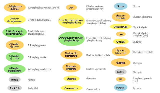
The vector stencils library "Carbohydrate metabolism" contains 25 icons of metabolite symbols.
Use these shapes for drawing carbohydrate metabolism schematics, biochemical diagrams and metabolic pathways maps.
"Carbohydrates are a superior short-term fuel for organisms because they are simpler to metabolize than fats or those amino acids (components of proteins) that can be used for fuel. In animals, the most important carbohydrate is glucose. The concentration of glucose in the blood is used as the main control for the central metabolic hormone, insulin. Starch, and cellulose in a few organisms (e.g., some animals ... and ... microorganisms), both being glucose polymers, are disassembled during digestion and absorbed as glucose. Some simple carbohydrates have their own enzymatic oxidation pathways, as do only a few of the more complex carbohydrates. The disaccharide lactose, for instance, requires the enzyme lactase to be broken into its monosaccharides components; many animals lack this enzyme in adulthood." [Carbohydrate metabolism. Wikipedia]
The shapes example "Design elements - Carbohydrate metabolism" is included in the Biology solution from the Science and Education area of ConceptDraw Solution Park.
Carbohydrate metabolite symbols
The vector stencils library "General window elements" contains 31 window elements.
Use this window UI icon set to design graphic user interface (GUI) of your software application for OS X 10.10 Yosemite Apple Mac operating system.
The example "General window elements - Vector stencils library" was created using the ConceptDraw PRO diagramming and vector drawing software extended with the Mac OS User Interface solution from the Software Development area of ConceptDraw Solution Park.
Main app window area

Main sidebar
Window panel
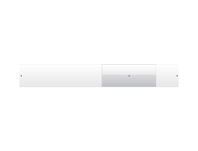
General slider
Volume slider
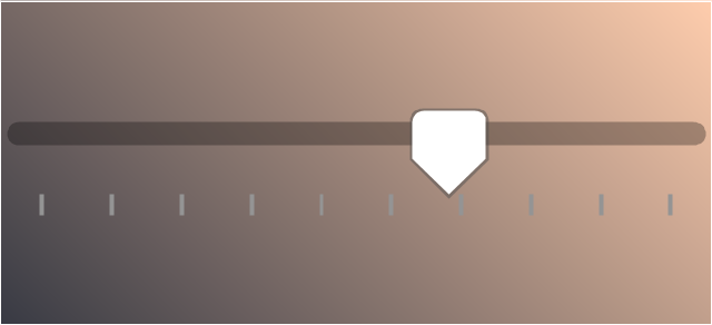
Audio level
Divider line

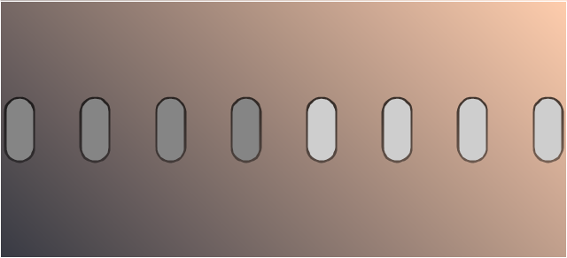
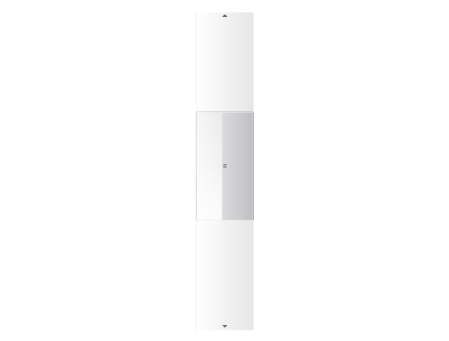
Scroll bar

Text label

Radio button

Radio button - selected

Check box
Check box - selected

Stepper control

Disclosure button - point down

Disclosure button - point up

Help button

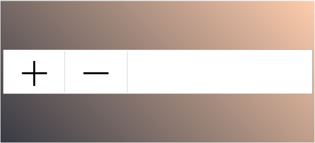
Add / subtract accounts
Text field
Text field - selected
Push button

Push button - active

Pop-up menu
Group box
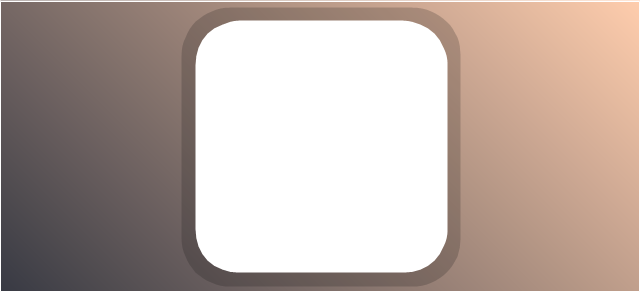
Image well

Left segment button

Center segment button

Right segment button

Left segment button - active

Center segment button - active

Right segment button - active

Basic Flowchart Symbols and Meaning


The vector stencils library "Ribbon interface" contains 41 ribbon shapes.
Use it for designing Microsoft ribbon graphic user interface (GUI) of software for Windows computers in the ConceptDraw PRO diagramming and vector drawing software extended with the Graphic User Interface solution from the Software Development area of ConceptDraw Solution Park.
Use it for designing Microsoft ribbon graphic user interface (GUI) of software for Windows computers in the ConceptDraw PRO diagramming and vector drawing software extended with the Graphic User Interface solution from the Software Development area of ConceptDraw Solution Park.
Main Window with Menu
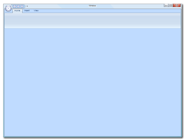
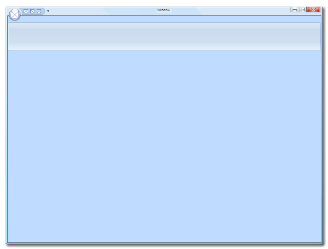
Main Window
Menu

Special Menu
Field

Tools Group
Tools Group Minimized
Tool Button

Tool Button

Toolbar
Label

Text Label

Edit Box
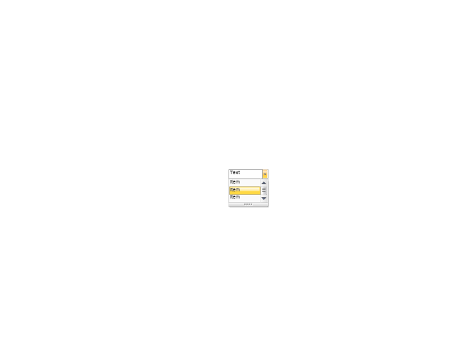
Combobox
Combobox with List
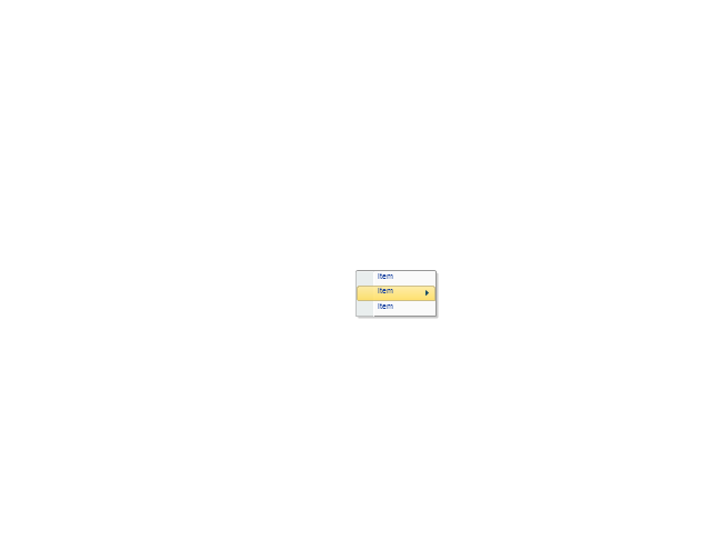
Drop-down Menu
Spin Box
Check Box

Radio Button

Styles Control 1
Styles Control 2

Rounded Tab

Floating Dialogue

Status Bar

Small Toolbar (for Status Bar)
-ribbon-interface---vector-stencils-library.png--diagram-flowchart-example.png)
Zoom Slider

Horizontal Scroll
Vertical Scroll
Drop-down List

Arrow
Close

Drop-down Menu Base

Drop-down Menu Left Part

Menu/List Item (Text)
-ribbon-interface---vector-stencils-library.png--diagram-flowchart-example.png)
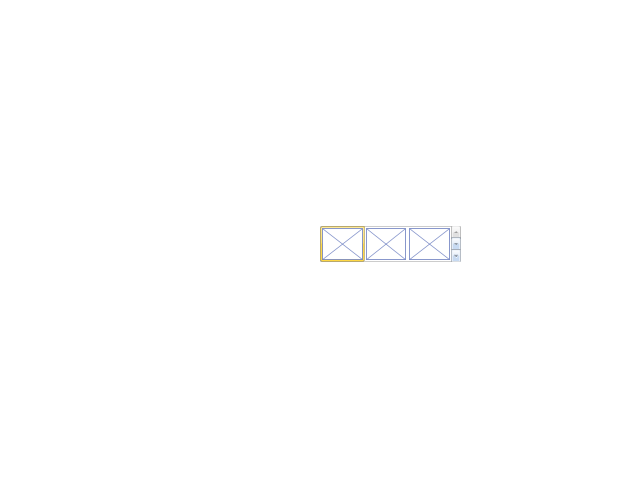
Menu/List Item (Image)
-ribbon-interface---vector-stencils-library.png--diagram-flowchart-example.png)
Menu/List Item (Image with Text)
-ribbon-interface---vector-stencils-library.png--diagram-flowchart-example.png)
Meny/List Header

Drop-down Menu Separator

Vertical Separator

Chek/Option for Drop-down Menu
Image

Process Flowchart


The vector stencils library "Electrical and telecom" contains 83 symbols of electrical and telecommunication equipment.
Use these shapes for drawing electrical and telecom system design floor plans, cabling layout schemes, and wiring diagrams in the ConceptDraw PRO diagramming and vector drawing software.
The vector stencils library "Electrical and telecom" is included in the Electric and Telecom Plans solution from the Building Plans area of ConceptDraw Solution Park.
Use these shapes for drawing electrical and telecom system design floor plans, cabling layout schemes, and wiring diagrams in the ConceptDraw PRO diagramming and vector drawing software.
The vector stencils library "Electrical and telecom" is included in the Electric and Telecom Plans solution from the Building Plans area of ConceptDraw Solution Park.
Luminaire ceiling mount
Enclosed ceiling luminaire
Wall light
1-light bar
2-light bar
4-light bar
6-light bar
8-light bar
Down lighter
Outdoor lightning
Outdoor lightning, bollard
Batten fluorescent, 1 lamp
Batten fluorescent, 2 lamps
Batten fluorescent, 3 lamps
Batten fluorescent, 4 lamps
Surface Fluorescent Light
Modular fluorescent fitting
Modular fluorescent fitting, inverter
Modular fluorescent fitting 2
Pull-cord switch
Emergency light
Emergency light 2
Emergency sign
Switch
Switch, 1 pole
Switch, 2 pole
Switch, 2-way
Multi-switch
Switch, intermediate
Dimmer switch
Dimmer switch 2
Socket
Socket 2
Switched socket
Switched socket 2
Double socket
Double socket 2
Socket outlet
Telephone outlet
Telephone outlet 2
Stereo outlet
Television outlet
Service panel, surface
Service panel, inset
Thermostat
Ceiling fan
Hold open unit
Detector
Fire alarm
City Fire Alarm Station
Fire Alarm Station
Fire Alarm Bell
Fire Alarm Central Station
Automatic Fire Alarm Device
Main control
Ground
Doorbell
Push Button
Buzzer
Annunciator
Horn
Maid's Signal Plug
Signal Central Station
Doorbell Chime
Doorbell Transformer
Magnetic Door Hold
Intercom
Telephone Key System
Digital Satellite System
Inside Antenna
Outside Antenna
Electric Motors
Single Phase
Three of Poly Phase
Wall Mounted Electrical Junction Box for Hardware
Wall Mounted Telephone/Data Junction Box for Hardware
Card Reader Access System
Emergency Release Button
Motion Sensor
Electric Door Opener
Watchman's Station
Watchman's Central Station
Battery
Total Quality Management Value

The vector stencils library "Valve assembly" contains 141 symbols of pressure and flow regulators, flow direction indicators, controls, and symbols to design flow paths of control valves.
Use these valve assembly shapes to design the engineering drawings of hydraulic and pneumatic valve assemblies in fluid power systems.
"Control valves are valves used to control conditions such as flow, pressure, temperature, and liquid level by fully or partially opening or closing in response to signals received from controllers that compare a "setpoint" to a "process variable" whose value is provided by sensors that monitor changes in such conditions.
The opening or closing of control valves is usually done automatically by electrical, hydraulic or pneumatic actuators. Positioners are used to control the opening or closing of the actuator based on electric, or pneumatic signals.
A control valve consists of three main parts in which each part exist in several types and designs: Valve's actuator, Valve's positioner, Valve's body.
" [Control valves. Wikipedia]
The shapes example "" was created using the ConceptDraw PRO diagramming and vector drawing software extended with the Mechanical Engineering solution from the Engineering area of ConceptDraw Solution Park.
Valve assembly symbols

- Symbol Main Control
- Main Control Point Electrical
- Electrical Symbol Main Control
- Electrical Main Control Intake Point Symbol
- Main Control Intake Point
- Symbol Main Intake Control
- Digital unit ventilator control - HVAC plan | Electrical and telecom ...
- Symbols Of Main Switch Lighting
- Security system floor plan | Design elements - Alarm and access ...
- Design elements - HVAC controls | Design elements - Alarm and ...
- Design elements - Alarm and access control | Security system floor ...
- Security system floor plan | How To use House Electrical Plan ...
- Design elements - Alarm and access control | Security Plans ...
- Design elements - Alarm and access control | How To use House ...
- Design elements - HVAC controls | How To use House Electrical ...
- Symbol For Control Transformer
- Design elements - Initiation and annunciation | How To use House ...
- Alarm Control Equipment
- Design elements - Alarm and access control
- Design elements - Alarm and access control | Design elements ...