Home Electrical Plan
Planning and construction of any building begins from the designing its floor plan and a set of electrical, telecom, piping, ceiling plans, etc. Solutions of Building Plans Area of ConceptDraw Solution Park can effectively help you develop all these plans. Let's design the Home Electrical Plan in ConceptDraw DIAGRAM quick and easy.Making Mechanical Diagram
The engineering diagrams produced with ConceptDraw DIAGRAM are vector graphic documents and are available for reviewing, modifying, and converting to a variety of formats (image, HTML, PDF file, MS PowerPoint Presentation, Adobe Flash or MS Visio XML).Interior Design. Site Plan — Design Elements
Site plans are large scale drawings that illustrate a lot of useful information, such as location of buildings on the surrounding territories, topography of the site, roads, footpaths, paved and hardstandings areas, ramps, parking areas, fencing, walls and gates, landscape elements, trees and plants, layout of external lighting and service runs, adjoining and adjacent structures, surrounding streets, and many other details. On each Site plan are also designated the scale, dimensions, site boundaries, key materials, and other additional notes. ConceptDraw DIAGRAM diagramming and interior design software extended with Site Plans solution from Building Plans area contains Parking and Roads, Site Accessories, Trees and Plants libraries with numerous collection of ready-to-use vector design elements for drawing detailed Site plans, Site design plans, Structural site plans, Landscape drawings for any locality and of any complexity without efforts. This software will be also useful for planning the parks, creation yard layouts, development residential and commercial landscape designs.Functional Block Diagram
You need design the Functional Block Diagram and dream to find the useful tools to draw it easier, quickly and effectively? ConceptDraw DIAGRAM offers the Block Diagrams Solution from the "Diagrams" Area which will help you!How to Draw a Building Plans
ConceptDraw DIAGRAM is a world-class diagramming platform that lets you display, communicate, and present dynamically. It′s powerful enough to draw everything from basic flowcharts to complex engineering schematics.Building Plan Software. Building Plan Examples
The correct implementation of large and complex construction projects is not possible without a well developed building concept and architectural project, which includes a huge spectrum of different plans and technical drawings. The obligatory package of plans typically contains a general plan of a building, detailed floor plans, ceiling and lighting plans, plans of furniture placement, etc. These plans effectively visualize all aspects of a building and its surrounding area. ConceptDraw DIAGRAM is a powerful building plans design software, which provides the Building Plans area including 17 solutions useful for architects, designers, builders, and other people tightly related with a building process: Basic Floor Plans, Floor Plans, Electric and Telecom Plans, Fire and Emergency Plans, Plant Layout Plans, Security and Access Plans, Plumbing and Piping Plans, Reflected Ceiling Plans, HVAC Plans, Cafe Restaurant Plans, Gym and SPA Plans, Landscape & Garden, Office Layout Plans, School and Training Plans, Seating Plans, Site Plans, Sport Field Plans.Physical Security Plan
ConceptDraw DIAGRAM diagramming and vector drawing software extended with Security and Access Plans Solution from the Building Plans Area of ConceptDraw Solution Park is a powerful software for fast and easy drawing professional looking Physical Security Plan.Block Diagram Creator
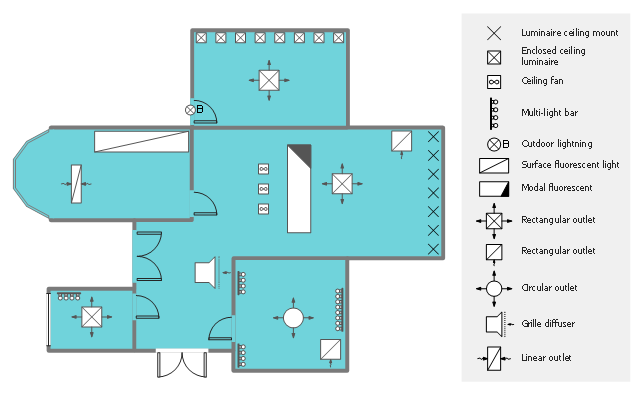
A block diagram is a diagram of a system in which the principal parts or functions are represented by blocks connected by lines that show the relationships of the blocks. ConceptDraw DIAGRAM diagramming and vector drawing software extended with Block Diagrams Solution from the "Diagrams" Area is a powerful Block Diagram Creator.This reflected ceiling plan (RCP) sample shows lighting and HVAC layout.
"A "reflected ceiling plan" shows a view of the room as if looking from above, through the ceiling, at a mirror installed one foot below the ceiling level, which shows the reflected image of the ceiling above. This convention maintains the same orientation of the floor and ceilings plans - looking down from above. Reflected Ceiling Plans or RCP's are used by designers and architects to demonstrate lighting, visible mechanical features, and ceiling forms as part of the documents provided for construction." [Floor plan. Wikipedia]
The lighting and HVAC layout example "Reflected ceiling plan" was created using the ConceptDraw DIAGRAM diagramming and vector drawing software extended with the Reflected Ceiling Plans solution from the Building Plans area of ConceptDraw Solution Park.
- Making Mechanical Diagram | Technical Drawing Software | Block ...
- Process Flowchart | Plant Layout Plans | Electrical Drawing Software ...
- How To use House Electrical Plan Software | Electrical Drawing ...
- Process Flowchart | Influence Diagram Software | Plumbing and ...
- Building Drawing Design Element: Piping Plan | Plumbing and ...
- Mechanical Fitting Symbols
- Mechanical Drawing Symbols | Piping and Instrumentation Diagram ...
- Plumbing and Piping Plans | Design elements - Pipes (part 1 ...
- Interior Plumbing Fitting Indication For Engineering Drawing
- Pipe Fitting Symbols Pdf
- Mechanical Engineering | Mechanical Drawing Symbols | Design ...
- Butt weld geometry | Mechanical Engineering | Mechanical Drawing ...
- How To use House Electrical Plan Software | Light Fitting ...
- Butt weld geometry | Mechanical Engineering | Design elements ...
- Mechanical Drawing Symbols | Retract resistor check valve ...
- Welding symbols | Mechanical Engineering | Design elements ...
- Mechanical Drawing Symbols | Interior Design Piping Plan - Design ...
- Mechanical Drawing Symbols | Design elements - Valves | Design ...
- Mechanical Drawing Symbols | Technical Drawing Software ...
- How To use House Electrical Plan Software | Home Electric Fitting ...


