UML Class Diagram Example - Medical Shop
State Diagram UML of Online Store. This sample was created in ConceptDraw DIAGRAM diagramming and vector drawing software using the UML Class Diagram library of the Rapid UML Solution from the Software Development area of ConceptDraw Solution Park. This sample shows the work of the medical shop and is used at the creation of the medical shop or pharmacy project, for understanding the process of shopping in the medical shop, for keeping purchases, for medical supplies.UML Notation
Unified Modeling Language (UML) is an open standard, the language of graphic description used for modeling objects in a field of software development and software engineering. It was created for definition, specification, visualization, designing and documenting software systems, as a unification of three object-oriented technologies Booch, OMT and OOSE, and uses the defined graphic notation for creating the visual models of object-oriented software systems. Description of UML consists of two parts, interactive and supplementing each other: UML semantics, which represents a certain metamodel, defines the abstract syntax and semantics of terms of object modeling with UML, and UML notation that is a graphic notation for visual representation of UML semantics. The powerful tools of the Rapid UML solution included to ConceptDraw Solution Park make the ConceptDraw DIAGRAM diagramming and vector drawing software the best for easy applying the UML notation when creating the visual models of object-oriented software systems and designing different kinds of UML diagrams.UML Class Diagram Notation
When it comes to system construction, a class diagram is the most widely used diagram. UML Class Diagrams is a type of static structure diagram that is used for general conceptual modeling of the systematics of the application. Such a diagram would illustrate the object-oriented view of a system. The object orientation of a system is indicated by a class diagram. It describes the structure of a system by showing the general issues,classes of a system, attributes, operations, interfaces, inheritance, and the relationships between them.How to create a UML Diagram
ConceptDraw DIAGRAM extended with the Rapid UML solution is perfect for drawing professional UML diagrams.UML Diagram for Mac
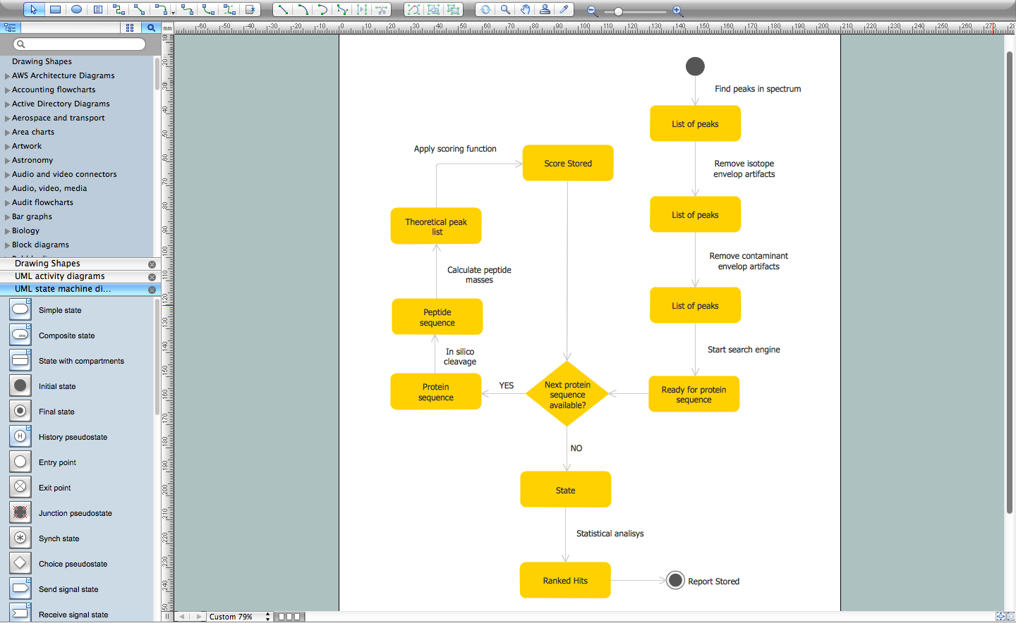
This sample was created on the Mac in ConceptDraw DIAGRAM diagramming and vector drawing software using the UML State Machine Diagram library of the Rapid UML Solution from the Software Development area of ConceptDraw Solution Park.- UML Class Diagram Example - Medical Shop | UML Notation | UML ...
- UML Class Diagram Example
- UML Class Diagram Example - Medical Shop | UML Notation |
- UML Class Diagram Example for Transport System | UML Tool ...
- UML Class Diagram Example - Social Networking Site | UML Class ...
- UML Class Diagram Example - Medical Shop - Conceptdraw.com
- UML Class Diagram Example - Medical Shop
- UML Class Diagram
- UML Sample Project | UML 2 4 Process Flow Diagram | UML Use ...
- Diagramming Software for Design UML State Machine Diagrams ...
- UML Diagrams with ConceptDraw PRO | UML Class Diagram ...
- Data Flow Diagrams | UML Class Diagrams . Diagramming Software ...
- UML Component Diagram Example - Online Shopping | UML Tool ...
- UML Component Diagram Example - Online Shopping ...
- UML Class Diagram Example - Medical Shop | Types of Flowchart ...
- Fishbone Diagram | Entity-Relationship Diagram (ERD) | UML ...
- Diagramming Software for Design UML Use Case Diagrams | UML ...
- UML Use Case Diagram Example Social Networking Sites Project ...
- UML Deployment Diagram Example - ATM System | UML Use Case ...
- UML Class Diagram Example - Medical Shop


