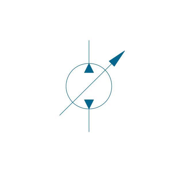
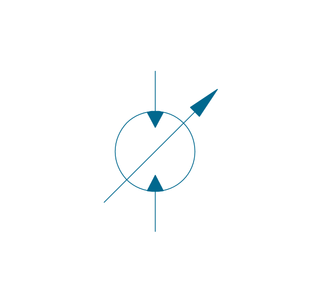
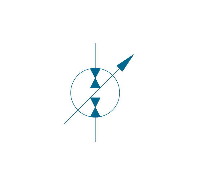
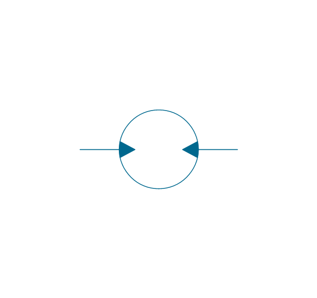
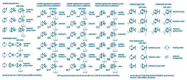
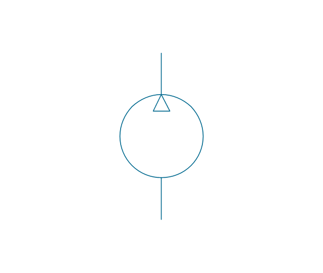
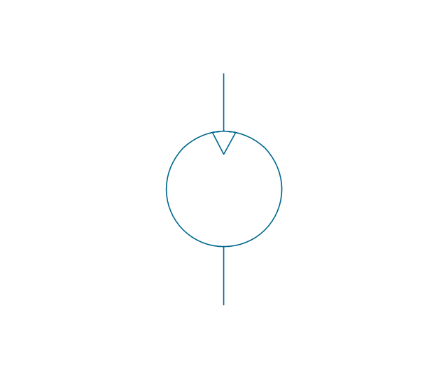
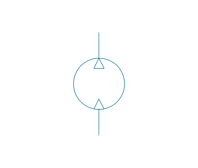
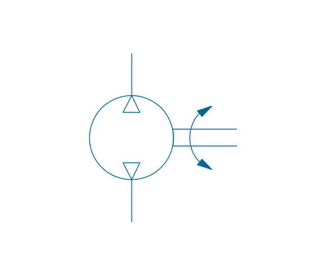
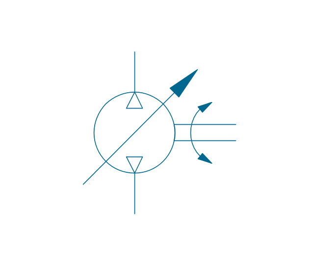
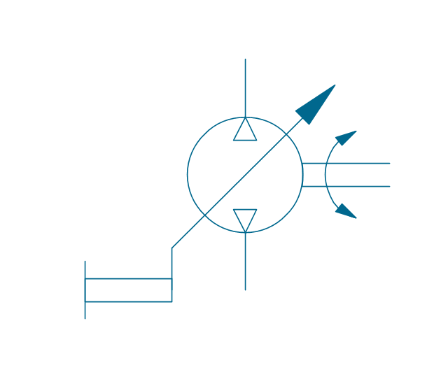
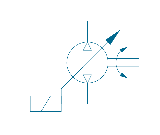
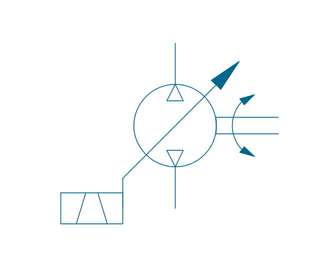
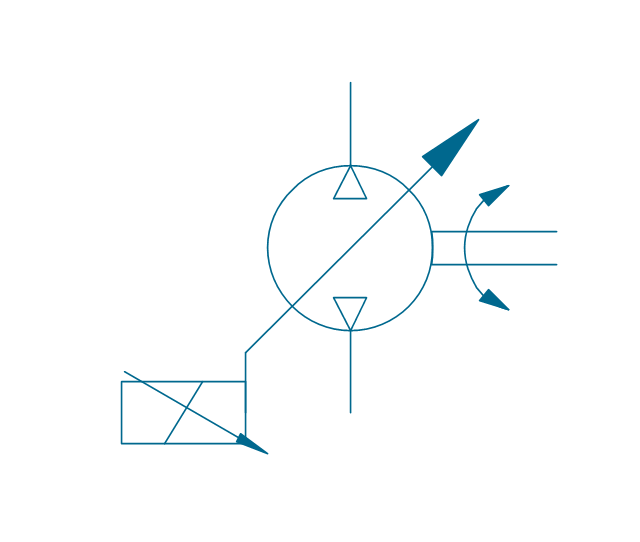
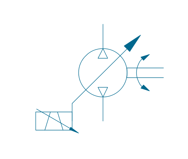
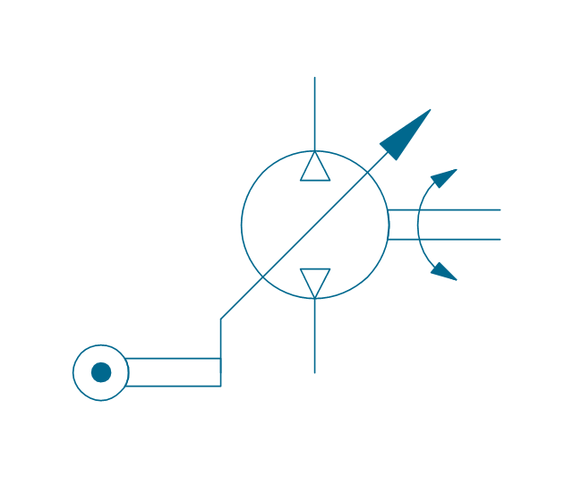
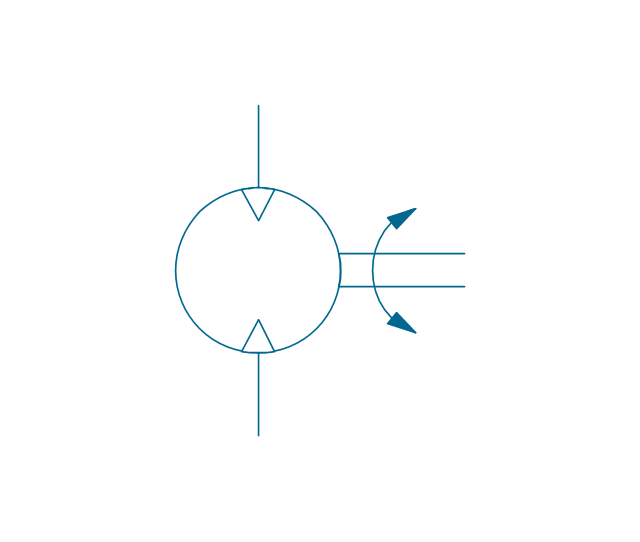
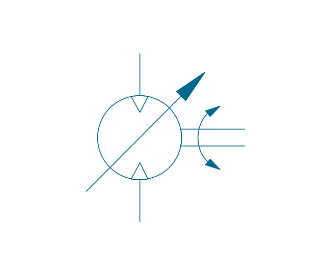
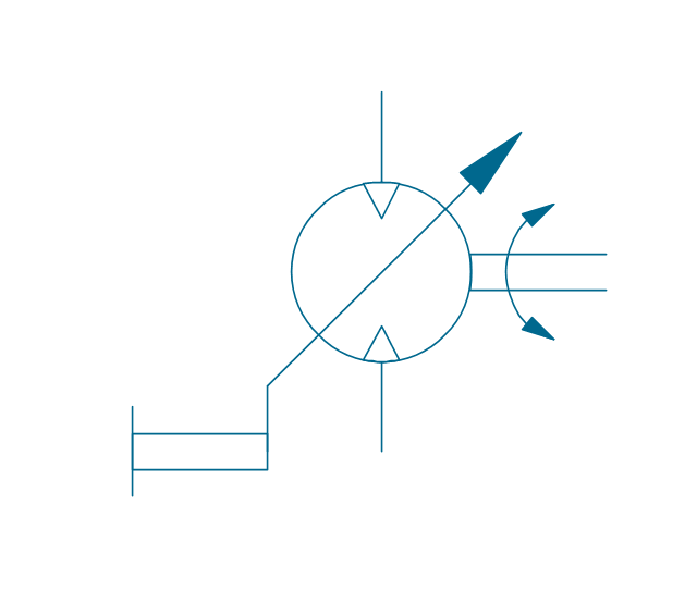
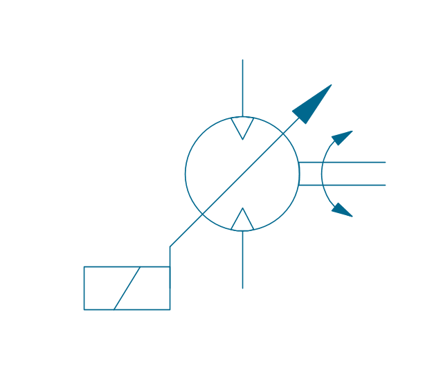
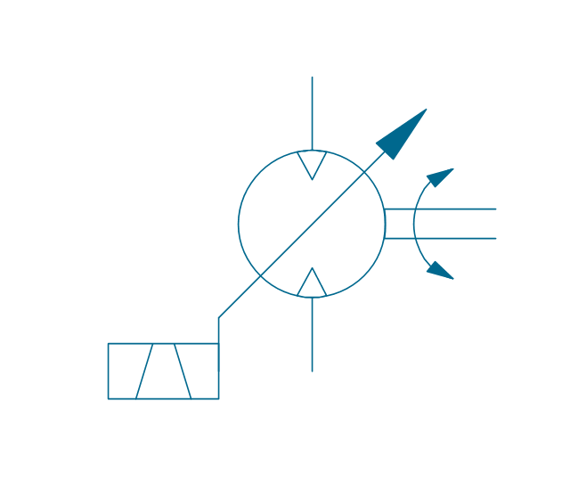
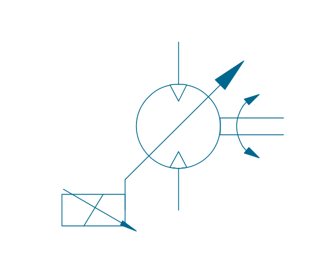
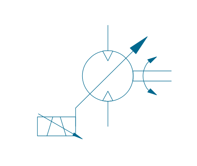
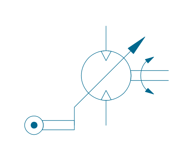
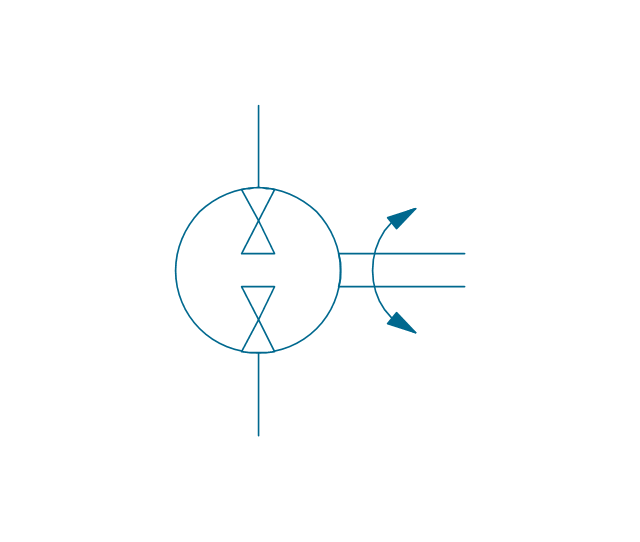
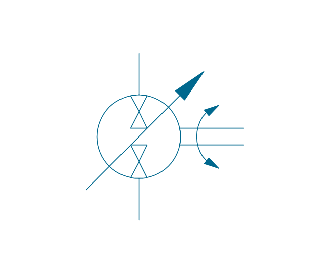
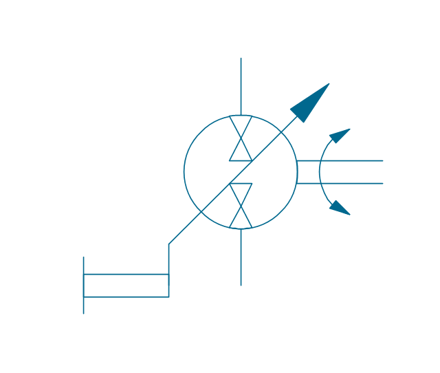
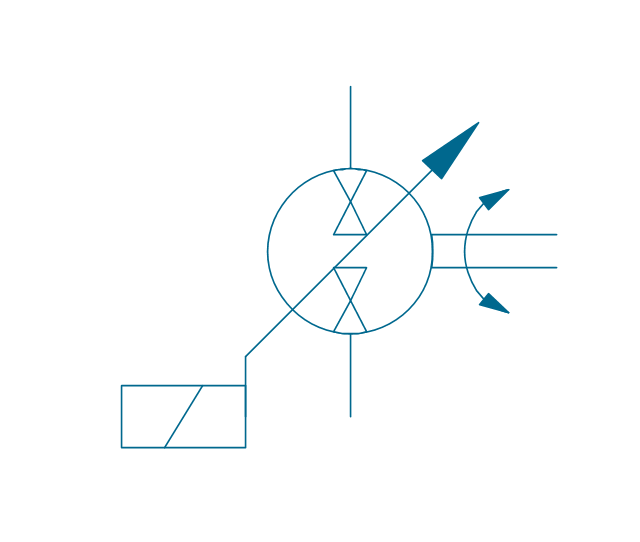
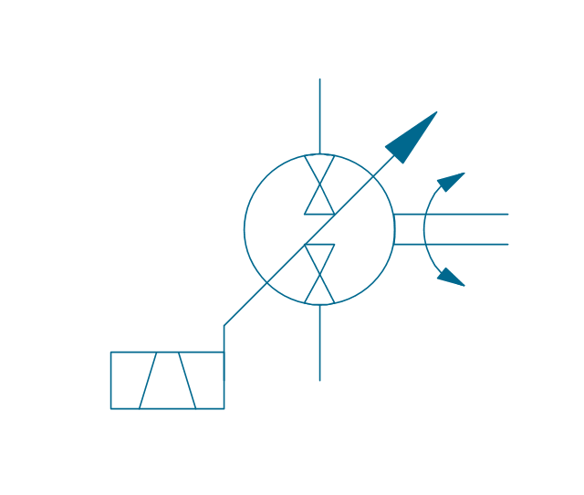
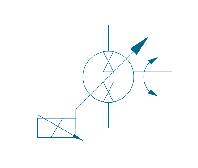
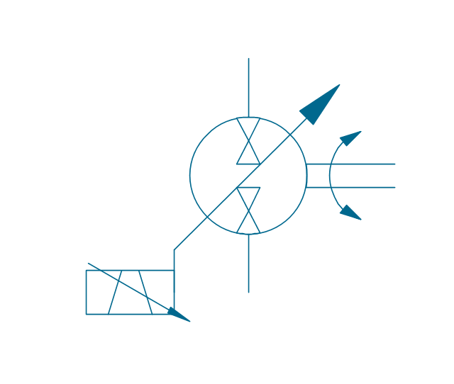
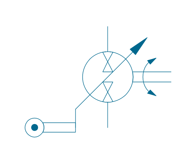
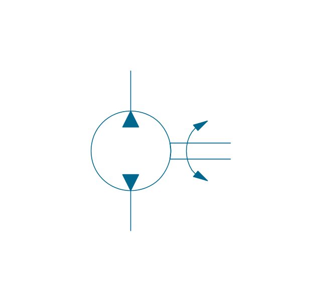
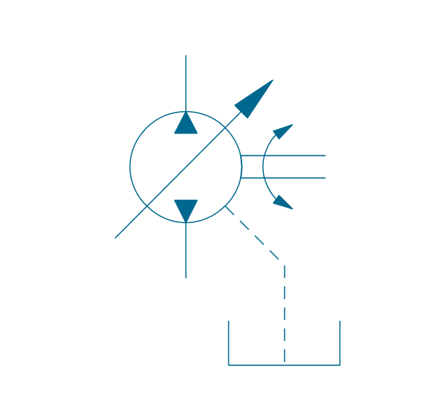
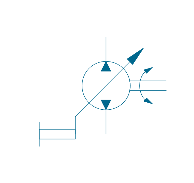
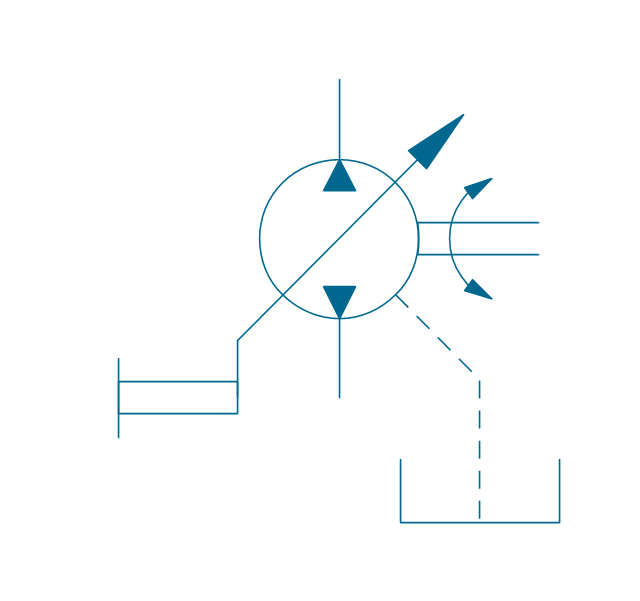
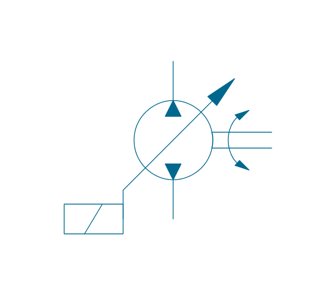
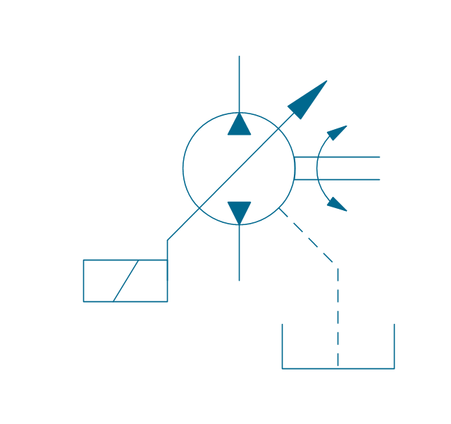
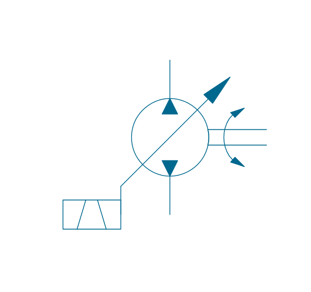
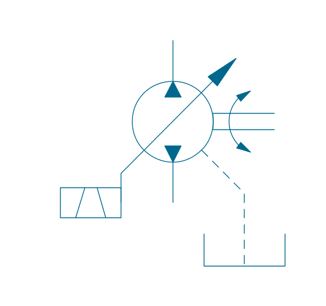
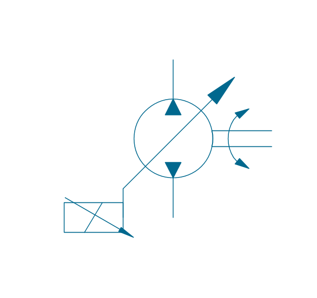
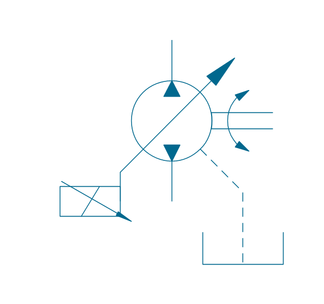
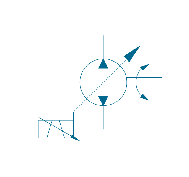
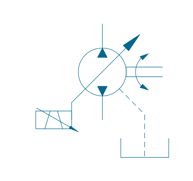
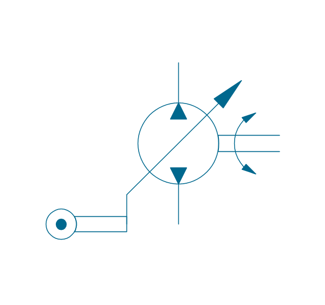
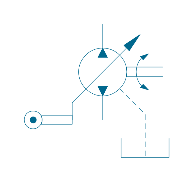
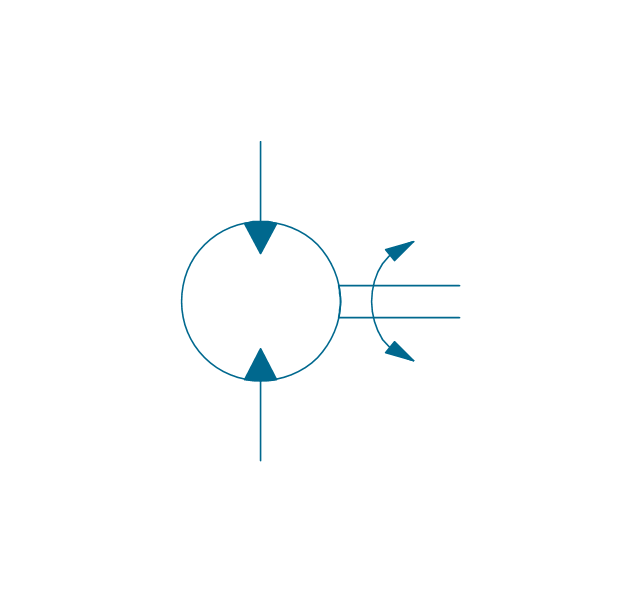
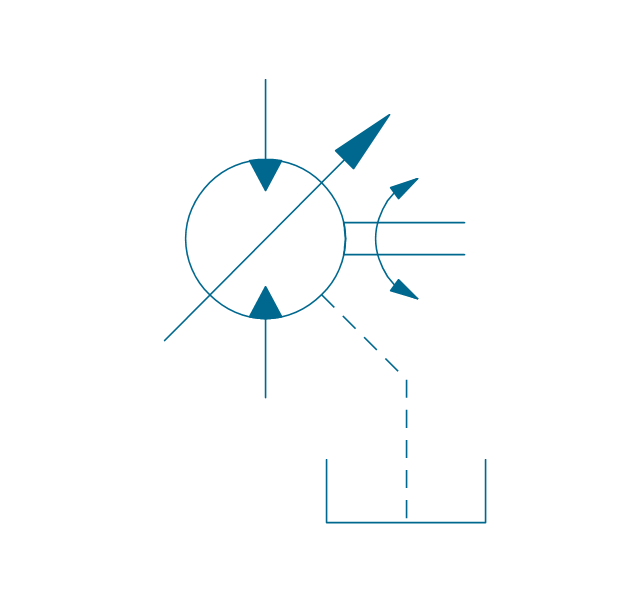
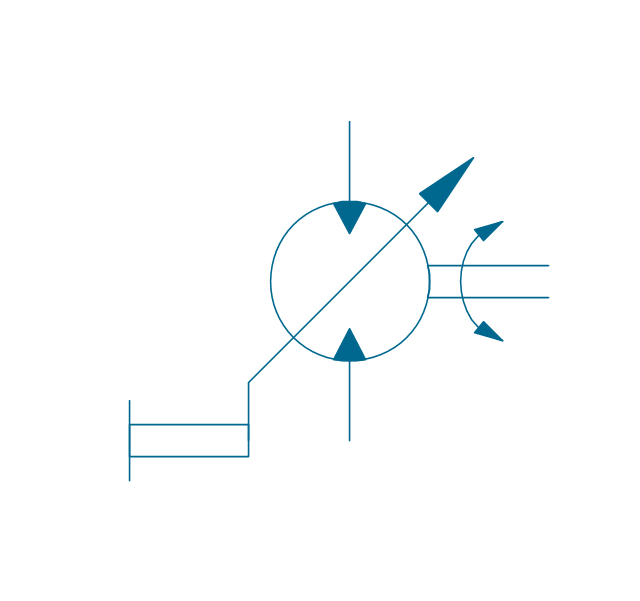
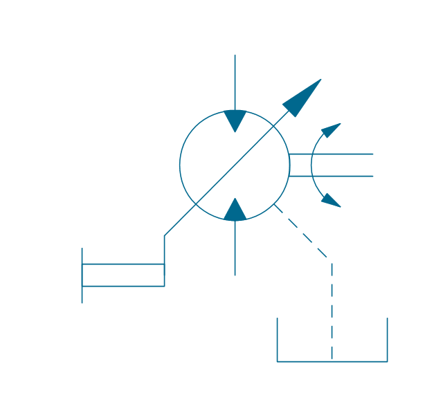
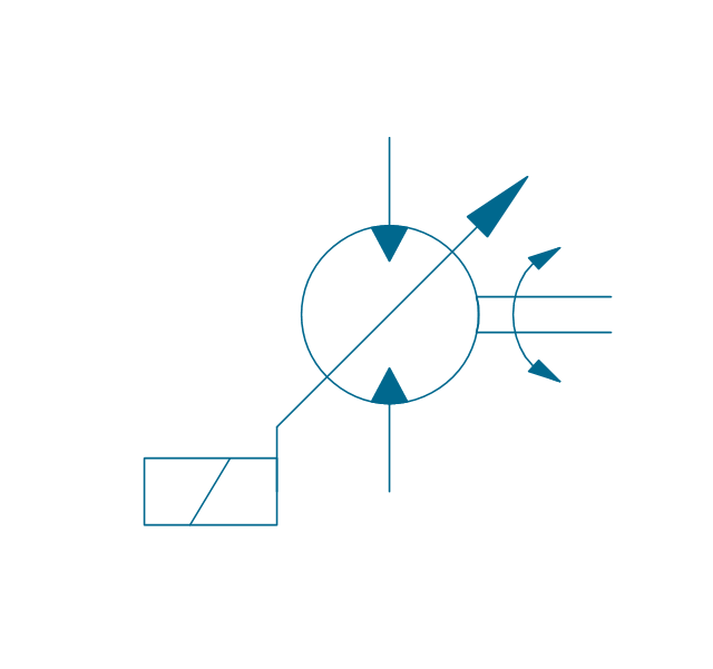
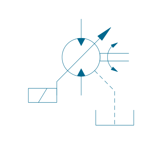
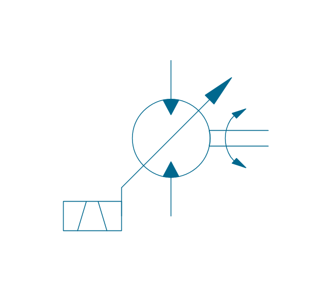
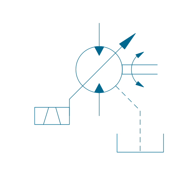
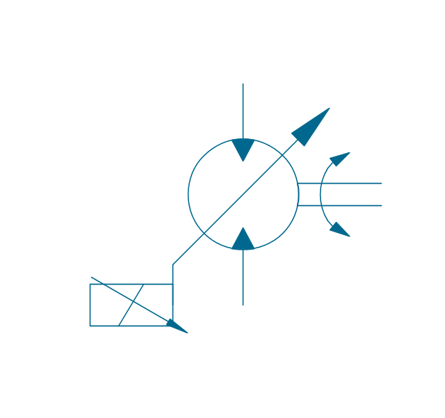
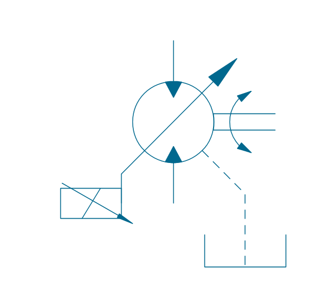
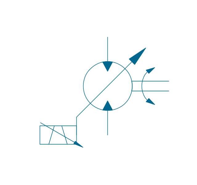
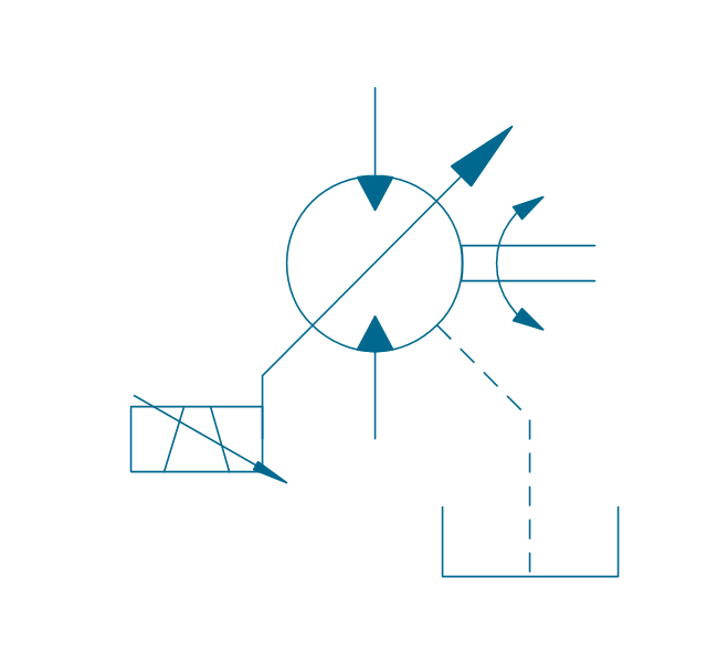
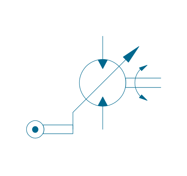
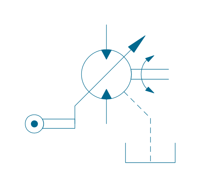
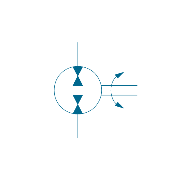
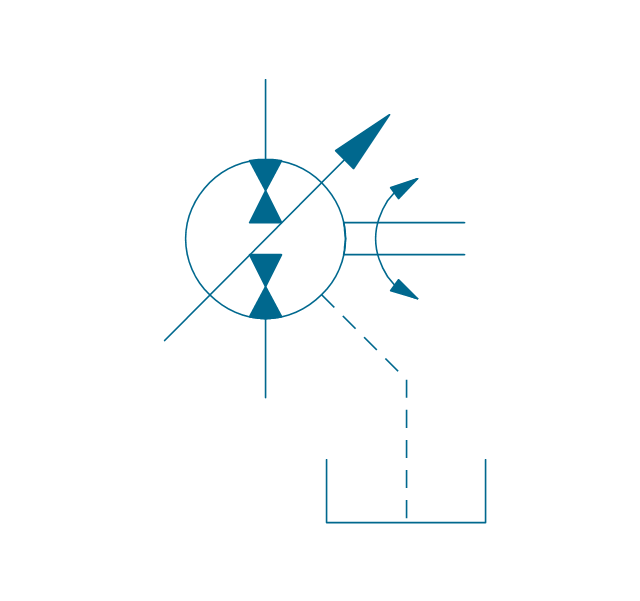
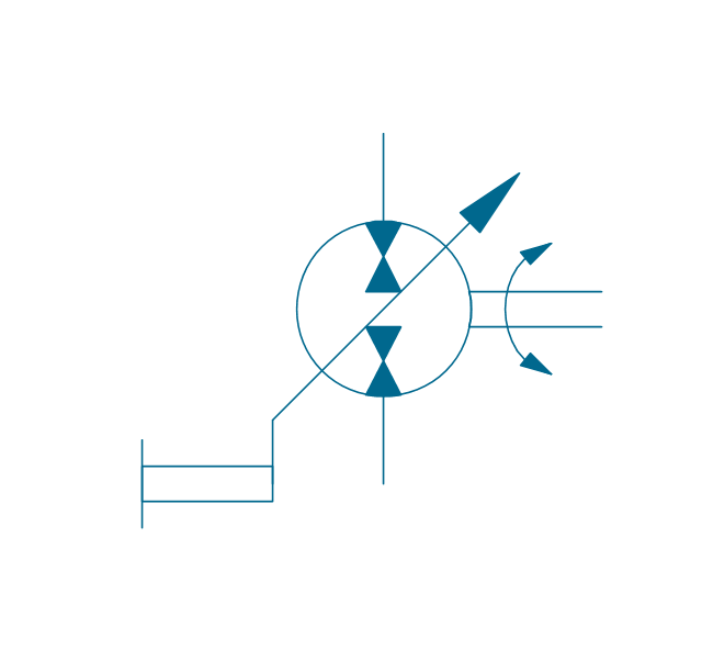
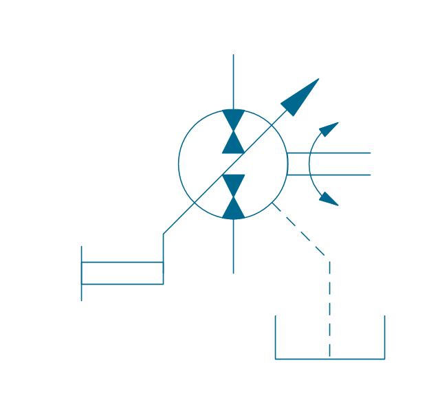
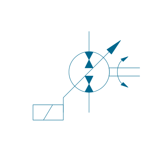
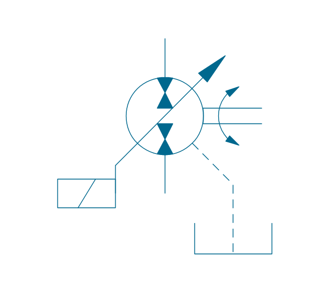
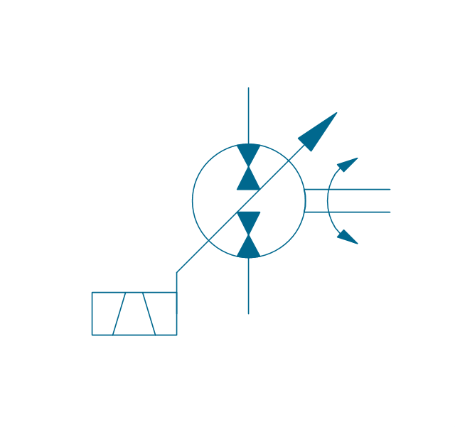
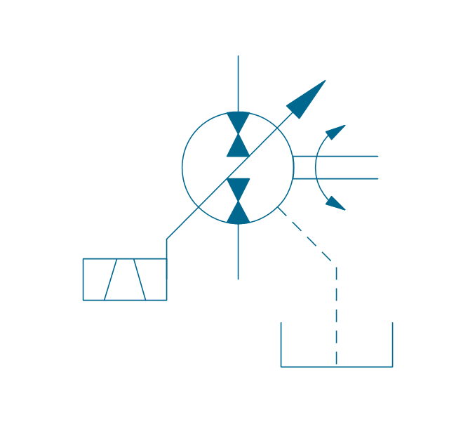
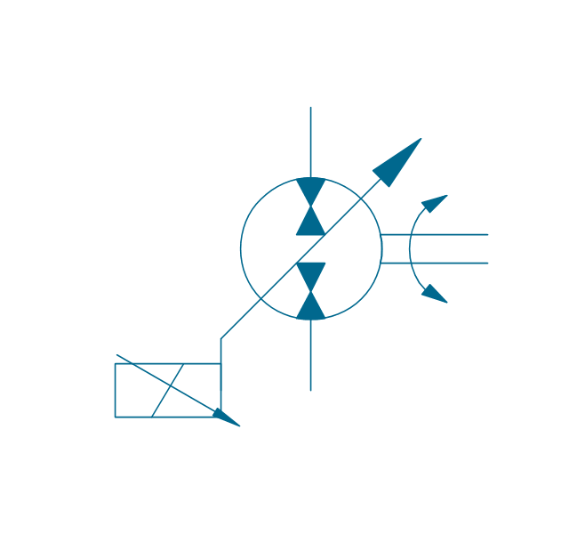
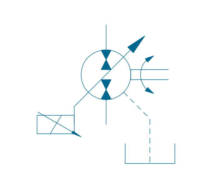
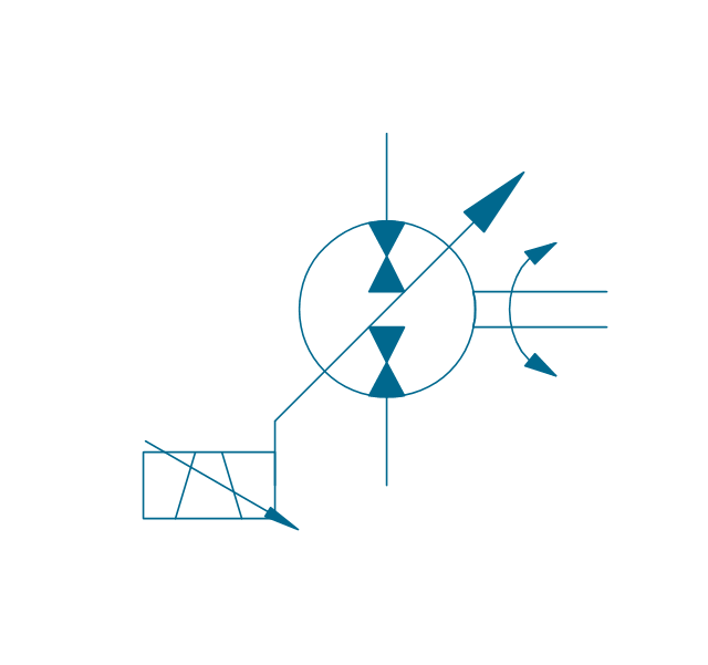
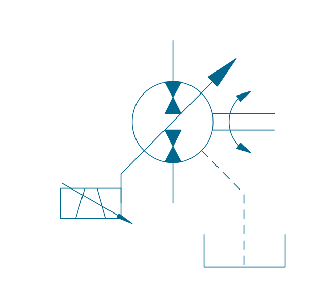
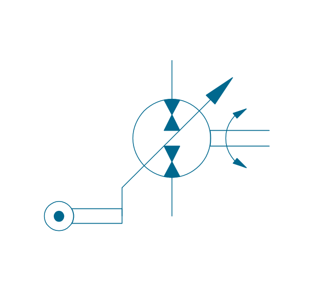
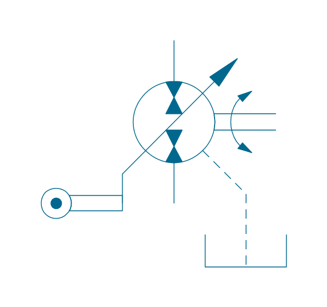
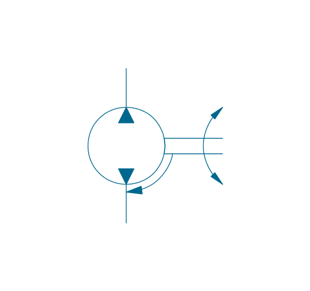
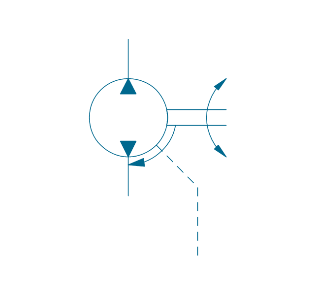
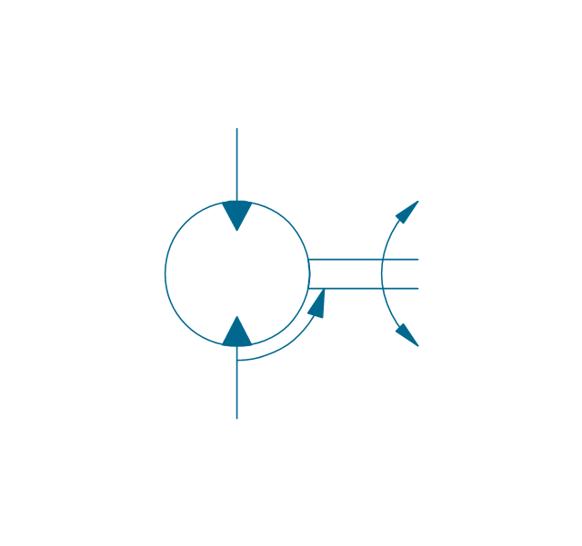
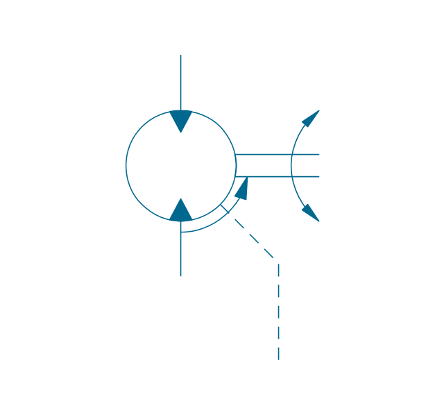
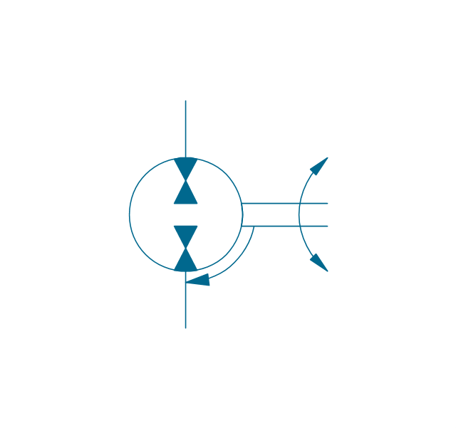
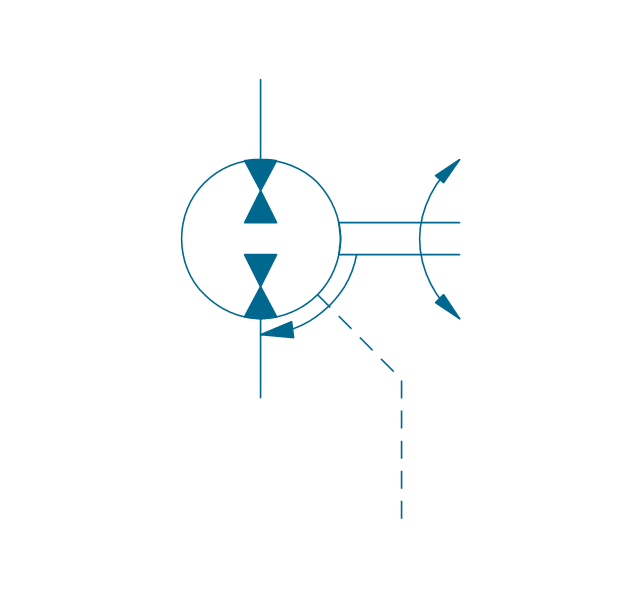
The vector stencils library "Hydraulic pumps and motors" contains 74 symbols of hydraulic pump vector stencils, hydraulic motor symbols for engineering drawings of fluid power and hydraulic control systems.
"Hydraulic pumps are used in hydraulic drive systems and can be hydrostatic or hydrodynamic.
Hydrostatic pumps are positive displacement pumps while hydrodynamic pumps can be fixed displacement pumps, in which the displacement (flow through the pump per rotation of the pump) cannot be adjusted, or variable displacement pumps, which have a more complicated construction that allows the displacement to be adjusted." [Hydraulic pump. Wikipedia]
"A hydraulic motor is a mechanical actuator that converts hydraulic pressure and flow into torque and angular displacement (rotation). The hydraulic motor is the rotary counterpart of the hydraulic cylinder.
Conceptually, a hydraulic motor should be interchangeable with a hydraulic pump because it performs the opposite function - much as the conceptual DC electric motor is interchangeable with a DC electrical generator. However, most hydraulic pumps cannot be used as hydraulic motors because they cannot be backdriven. Also, a hydraulic motor is usually designed for the working pressure at both sides of the motor.
Hydraulic pumps, motors, and cylinders can be combined into hydraulic drive systems. One or more hydraulic pumps, coupled to one or more hydraulic motors, constitutes a hydraulic transmission." [Hydraulic motor. Wikipedia]
The shapes example "Design elements - Hydraulic pumps and motors" was created using the ConceptDraw PRO diagramming and vector drawing software extended with the Mechanical Engineering solution from the Engineering area of ConceptDraw Solution Park.
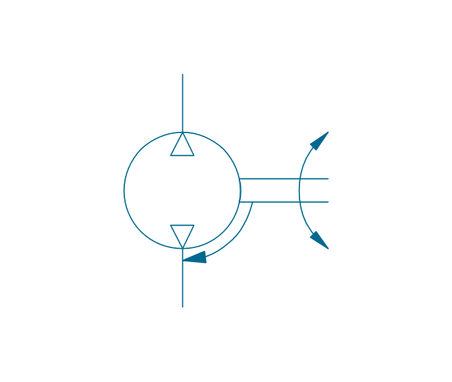
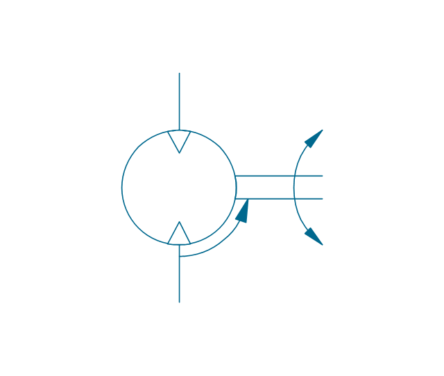
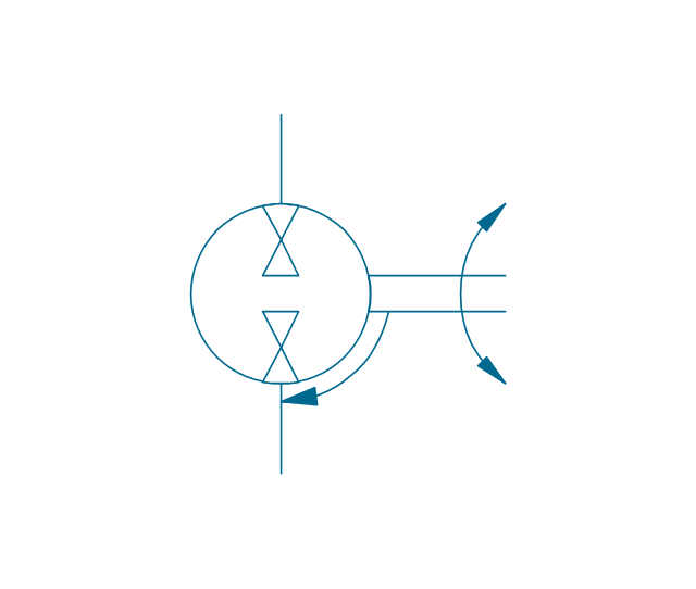
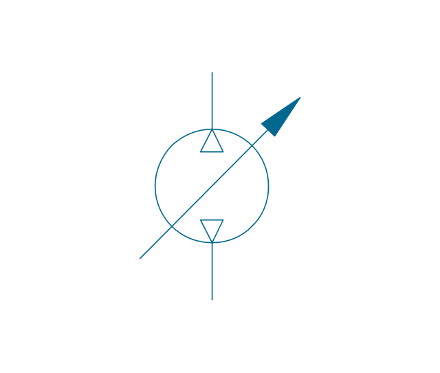
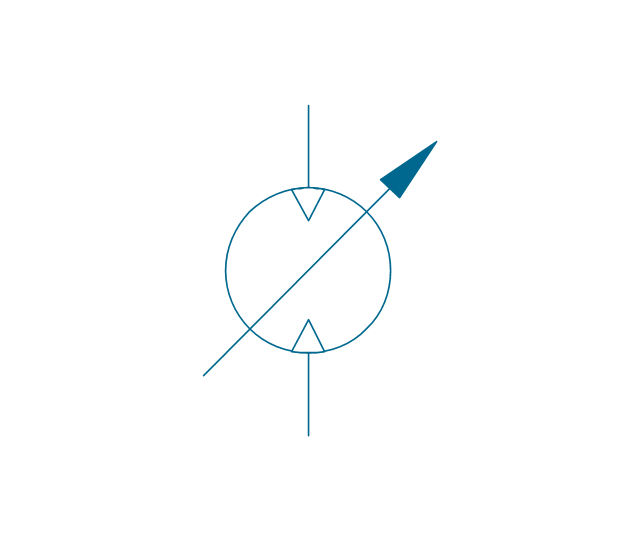
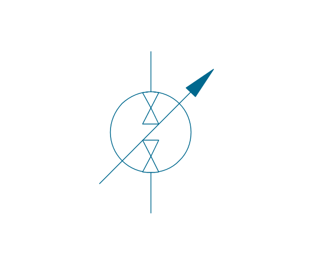
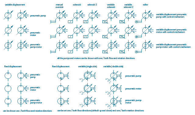
The vector stencils library "Pneumatic pumps and motors" contains 39 symbols of pneumatic pumps, motors and pump-motors.
Use these shapes for designing the engineering drawings of pneumatic circuits in the ConceptDraw PRO diagramming and vector drawing software extended with the Mechanical Engineering solution from the Engineering area of ConceptDraw Solution Park.
www.conceptdraw.com/ solution-park/ engineering-mechanical
The vector stencils library "Pneumatic pumps and motors" contains 39 symbols of pneumatic pumps, motors and pump-motors for designing the engineering drawings of pneumatic circuits.
"A pneumatic motor or compressed air engine is a type of motor which does mechanical work by expanding compressed air. Pneumatic motors generally convert the compressed air energy to mechanical work through either linear or rotary motion. Linear motion can come from either a diaphragm or piston actuator, while rotary motion is supplied by either a vane type air motor or piston air motor." [Pneumatic motor. Wikipedia]
"A gas compressor is a mechanical device that increases the pressure of a gas by reducing its volume. An air compressor is a specific type of gas compressor.
Compressors are similar to pumps: both increase the pressure on a fluid and both can transport the fluid through a pipe. As gases are compressible, the compressor also reduces the volume of a gas. Liquids are relatively incompressible; while some can be compressed, the main action of a pump is to pressurize and transport liquids." [Gas compressor. Wikipedia]
The shapes example "Design elements - Pneumatic pumps and motors" was created using the ConceptDraw PRO diagramming and vector drawing software extended with the Mechanical Engineering solution from the Engineering area of ConceptDraw Solution Park.
The vector stencils library "Hydraulic pumps and motors" contains 74 symbols of hydraulic equipment.
Use these shapes for engineering drawings of fluid power and hydraulic control systems in the ConceptDraw PRO diagramming and vector drawing software extended with the Mechanical Engineering solution from the Engineering area of ConceptDraw Solution Park.
www.conceptdraw.com/ solution-park/ engineering-mechanical
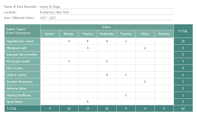
This check sheet example was redesigned from the Wikimedia Commons file: Check sheet for motor assembly.svg. [commons.wikimedia.org/ wiki/ File:Check_ sheet_ for_ motor_ assembly.svg]
This file is licensed under the Creative Commons Attribution-Share Alike 3.0 Unported license. [creativecommons.org/ licenses/ by-sa/ 3.0/ deed.en]
"The check sheet is a form (document) used to collect data in real time at the location where the data is generated. The data it captures can be quantitative or qualitative. When the information is quantitative, the check sheet is sometimes called a tally sheet.
The check sheet is one of the so-called Seven Basic Tools of Quality Control. ...
Kaoru Ishikawa identified five uses for check sheets in quality control:
- To check the shape of the probability distribution of a process
- To quantify defects by type
- To quantify defects by location
- To quantify defects by cause (machine, worker)
- To keep track of the completion of steps in a multistep procedure (in other words, as a checklist)" [. Wikipedia]
The example "Check sheet for motor assembly" was created using the ConceptDraw PRO software extended with the Seven Basic Tools of Quality solution from the Quality area of ConceptDraw Solution Park.
Used Solutions
Quality
>
 Mechanical Engineering
This solution extends ConceptDraw PRO v.9 mechanical drawing software (or later) with samples of mechanical drawing symbols, templates and libraries of design elements, for help when drafting mechanical engineering drawings, or parts, assembly, pneumatic,
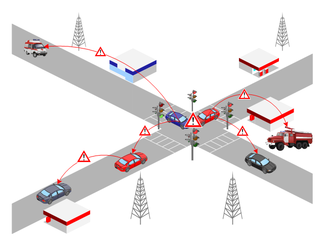
This VANET diagram example was drawn on the base of picture from the webpage "Security and Privacy in Location-based MANETs/ VANETs" from the Donald Bren School of Information and Computer Sciences, the University of California, Irvine. [ics.uci.edu/ ~keldefra/ manet.htm]
"A vehicular ad hoc network (VANET) uses cars as mobile nodes in a MANET to create a mobile network. A VANET turns every participating car into a wireless router or node, allowing cars approximately 100 to 300 metres of each other to connect and, in turn, create a network with a wide range. As cars fall out of the signal range and drop out of the network, other cars can join in, connecting vehicles to one another so that a mobile Internet is created. It is estimated that the first systems that will integrate this technology are police and fire vehicles to communicate with each other for safety purposes. Automotive companies like General Motors, Toyota, Nissan, DaimlerChrysler, BMW and Ford promote this term." [Vehicular ad hoc network. Wikipedia]
The VANET diagram example "Vehicular ad-hoc network" was created using the ConceptDraw PRO diagramming and vector drawing software extended with the Vehicular Networking solution from the Computer and Networks area of ConceptDraw Solution Park.
Used Solutions
Maps
>
- Hydraulic Motors Engineering Drawings
- Design elements - Hydraulic pumps and motors | Accounting ...
- Design elements - Hydraulic pumps and motors | Electrical Symbols ...
- Mechanical Drawing Symbols | Hydraulic pumps and motors ...
- Hydraulic circuits | Design elements - Hydraulic pumps and motors ...
- Design elements - Pneumatic pumps and motors | Mechanical ...
- Mechanical Drawing Symbols | Mechanical Engineering | Design ...
- Pneumatic pumps and motors - Vector stencils library
- Design elements - Hydraulic pumps and motors | Design elements ...
- Hydraulic pumps and motors - Vector stencils library
- Design elements - Pneumatic pumps and motors | Diaphragm Air ...
- Design elements - Pneumatic pumps and motors
- Design elements - Hydraulic pumps and motors | Complicated ...
- Design elements - Pneumatic pumps and motors | Pneumatic pumps ...
- Design elements - Hydraulic pumps and motors | Mechanical ...
- Design elements - Pneumatic pumps and motors | Design elements ...
- Design elements - Hydraulic pumps and motors | Pumps - Vector ...
- Design elements - Pneumatic pumps and motors | Pneumatic 5 ...
- Hydraulic pumps and motors - Vector stencils library | Pneumatic ...
-pneumatic-pumps-and-motors---vector-stencils-library.png--diagram-flowchart-example.png)
-pneumatic-pumps-and-motors---vector-stencils-library.png--diagram-flowchart-example.png)
-pneumatic-pumps-and-motors---vector-stencils-library.png--diagram-flowchart-example.png)
-pneumatic-pumps-and-motors---vector-stencils-library.png--diagram-flowchart-example.png)
-pneumatic-pumps-and-motors---vector-stencils-library.png--diagram-flowchart-example.png)
-pneumatic-pumps-and-motors---vector-stencils-library.png--diagram-flowchart-example.png)







-hydraulic-pumps-and-motors---vector-stencils-library.png--diagram-flowchart-example.png)
,-drain-hydraulic-pumps-and-motors---vector-stencils-library.png--diagram-flowchart-example.png)
-hydraulic-pumps-and-motors---vector-stencils-library.png--diagram-flowchart-example.png)
,-drain-hydraulic-pumps-and-motors---vector-stencils-library.png--diagram-flowchart-example.png)
-hydraulic-pumps-and-motors---vector-stencils-library.png--diagram-flowchart-example.png)
-hydraulic-pumps-and-motors---vector-stencils-library.png--diagram-flowchart-example.png)
,-drain-hydraulic-pumps-and-motors---vector-stencils-library.png--diagram-flowchart-example.png)
,-drain-hydraulic-pumps-and-motors---vector-stencils-library.png--diagram-flowchart-example.png)
-hydraulic-pumps-and-motors---vector-stencils-library.png--diagram-flowchart-example.png)
,-drain-hydraulic-pumps-and-motors---vector-stencils-library.png--diagram-flowchart-example.png)
-hydraulic-pumps-and-motors---vector-stencils-library.png--diagram-flowchart-example.png)
,-drain-hydraulic-pumps-and-motors---vector-stencils-library.png--diagram-flowchart-example.png)
