 Network Layout Floor Plans
Network Layout Floor Plans solution extends ConceptDraw DIAGRAM software functionality with powerful tools for quick and efficient documentation the network equipment and displaying its location on the professionally designed Network Layout Floor Plans. Never before creation of Network Layout Floor Plans, Network Communication Plans, Network Topologies Plans and Network Topology Maps was not so easy, convenient and fast as with predesigned templates, samples, examples and comprehensive set of vector design elements included to the Network Layout Floor Plans solution. All listed types of plans will be a good support for the future correct cabling and installation of network equipment.
Local area network (LAN). Computer and Network Examples
Local Area Network (LAN) is a network which consists of computers and peripheral devices connected each other and to the local domain server, and covers a little territory or small number of buildings, such as home, school, laboratory, office, etc. LAN serves for few hundreds of users. It includes many cables and wires, and demands to design previously a Network diagram. All local area network devices can use the shared printers and disk storage. ConceptDraw DIAGRAM is a perfect network diagramming software with examples of LAN Diagrams, templates and predesigned vector objects. ConceptDraw DIAGRAM is the ideal choice for network engineers and network designers who need to draw fast and easy Local Area Network Diagrams, for IT specialists, developers and other IT professionals which need to visualize the communication schemes of LAN and visually document the LAN's physical structure and arrangement in houses, offices and other buildings. Ready-to-use vector objects from Computer Network Diagrams solution will help you design LAN diagrams in minutes.
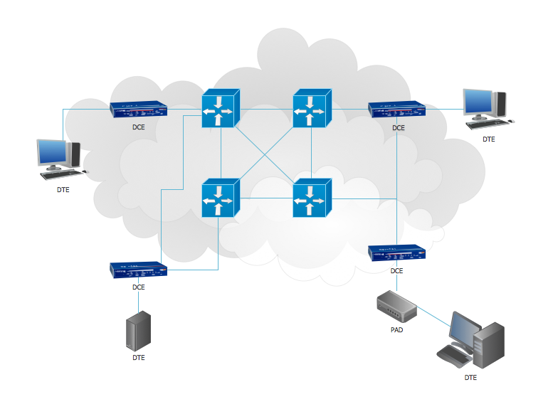
Telecommunication networks. Computer and Network Examples
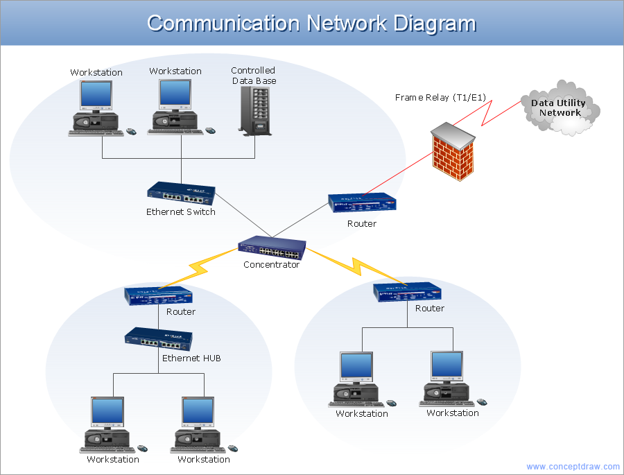
A Telecommunications network is a network of nodes, links, trunks and telephone switches that are connected, operated by telephone companies and realize telephone, audio, visual and data communications among the users. The telecommunications network can also include Internet, microwave, wireless equipment. This example was created in ConceptDraw DIAGRAM using the Computer and Networks Area of ConceptDraw Solution Park and shows the Telecommunications network.
Network Layout
The Network Layout Diagram visually illustrates the arrangement of computers, nodes and other network appliances, such as servers, printers, routers, switches, hubs, and their relationships between each other. The network layout and placement of servers greatly influence on the network security and network performance. Elaboration of robust Network Layout Diagram is especially important when visualizing already existing network in order to understand its complexity; when troubleshooting the network issues; designing, documenting and implementing new network configurations; extending, modifying, or moving an existing network to other location. Through the careful thinking the network plan and designing the clear Network Layout Diagram, you can be confident in result on the stage of network implementation and to solve faster the problems appearing in network infrastructure. ConceptDraw DIAGRAM enhanced with Computer Network Diagrams solution from Computer and Networks area perfectly suits for drawing Network Layout Diagrams for different network topologies.
Network wiring cable. Computer and Network Examples
To connect two or more network devices are used the network cables. There are more different types of the network cables: Coaxial cable, Optical fiber cable, Twisted Pair, Ethernet crossover cable, Power lines and others. They are used depending of the network topology, size, protocol. This example was created in ConceptDraw DIAGRAM using the Computer and Networks solution from the Computer and Networks area of ConceptDraw Solution Park.
Network Architecture
Network architecture is a design of the structure of communication network. Network architecture specifies network configuration, the main physical components of the network, products and services delivered via communication network, defines the components that characterize its common logical organization, technical support, software. It describes encoding methods, principles of operation and user interface. To graphically represent the network is used a Network Architecture Diagram. ConceptDraw DIAGRAM software is the best network diagramming tool that lets create in minutes your own professional Network diagrams from numerous templates and examples. Computer & Networks solution for ConceptDraw DIAGRAM software provides extensive libraries of vector stencils for drawing Network architecture diagrams and maps, Cisco network architectural drawings, Computer communication network design blueprints, TCP/IP network architecture diagrams for LANs and WANs, Network floor plan layouts, Logical network diagrams, Network communication plans, Web-based network diagrams, etc.
CCTV Network Example
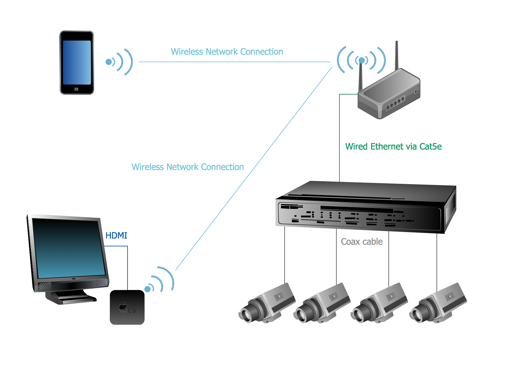
The following examples cctv network were created in ConceptDraw DIAGRAM diagramming and vector drawing software using the Audio, Video, Media Solution. Using this easily customizable cctv network template you can represent any existing cctv network.Butterfly Network. Computer and Network Examples
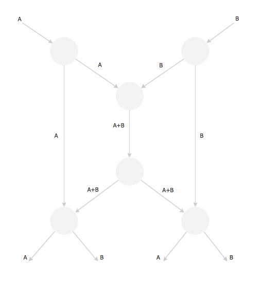
The Butterfly Network is the scheme that connects the units of a multiprocessing system and needs n stages to connect 2n processors. At the each stage the switch is thrown in depending of the particular bit in the addresses of the processors that are connected.
Network Visualization
Network visualization is widely used by network and system administrators, and others computer and network-related specialists. Never before the process of network visualization wasn't so easy as now thanks to the Network Layout Floor Plans Solution from the Computer and Networks Area.Digital Communications Network. Computer and Network Examples
The digital communication is a physical transfer of the data over a point-to-point or point-to-multipoint communication channel. Channels can be copper wires, optical fibres, wireless communication channels, etc. The data are realized as electromagnetic signals (radiowave, microwave, electrical voltage, etc.). This example was created in ConceptDraw DIAGRAM using the Computer and Networks Area of ConceptDraw Solution Park and shows the Digital Communication Network diagram.
Examples of Flowcharts, Org Charts and More
ConceptDraw DIAGRAM covers a broad spectrum of business graphics categories and offers at ConceptDraw STORE enormous online collection of pictorial examples and samples for different thematics and application areas. It is a plentiful source of inspiration and wonderful examples of professionally designed diagrams, flowcharts, UML diagrams, organizational charts, databases, ERDs, network diagrams, business charts, different thematic charts, schematics, infographics and plans developed specially for knowledge workers, engineers, managers, businessmen, marketing specialists, analytics, scientists, students, professors, journalists and also for a large number of other people that every day use various diagrams and drawings in their work and life activity. Each of these examples is a real art, all they are well thought-out and designed without efforts with help of powerful tools of ConceptDraw DIAGRAM software. ConceptDraw examples display all variety of tasks, possibilities and results that ConceptDraw Product Line lets achieve fast and easy. ConceptDraw is one of the best Visio alternatives for Mac. It open all Visio formats like.vsdx,.vss,.vdx files and allows you to export files to Visio formats.
Network Security Diagram
ConceptDraw DIAGRAM diagramming and vector drawing software enhanced with Network Security Diagrams Solution from the Computer and Networks Area of ConceptDraw Solution Park is the best for effective design professional, colorful and attractive Network Security Diagram of any complexity and degree of detailing.Café Floor Plan Example
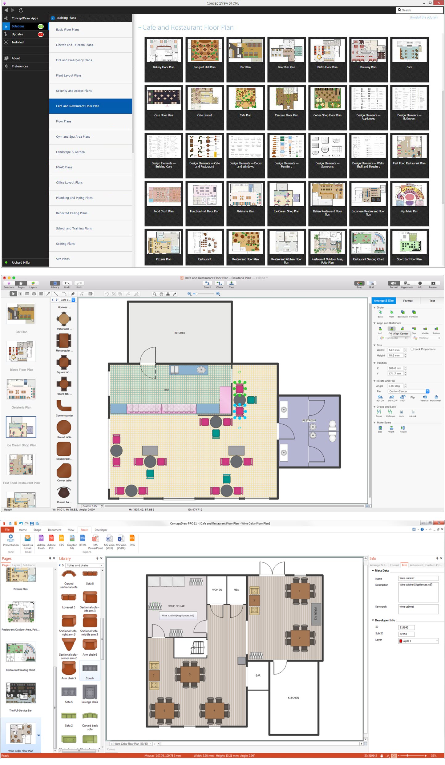
Development and drawing Cafe Layouts and Cafe Floor Plans is the most responsible and important stage at the process of cafe design and construction. On this stage modern architects, constructors and designers prefer apply the special and powerful design applications, which save their time and efforts. ConceptDraw DIAGRAM is the best diagramming and design software for drawing most functional and efficient Cafe floor plans, Cafe layouts, Cafe design plans, Restaurant floor plans, etc. ConceptDraw Solution Park includes Cafe and Restaurant Floor Plan solution at the Building Plans area, which offers special drawing tools, ready sample plans and templates for quick-start drawing, and also extensive set of predesigned vector design elements for construction the general plan of cafe, restaurant, or even banquet hall, the plans of arrangement the furniture, appliances and decor elements. Each included Cafe floor plan example or sample is well thought-out and designed by professionals, so can become a good basis or source of inspiration for your own Cafe floor plan.
 Office Layout Plans
Office layouts and office plans are a special category of building plans and are often an obligatory requirement for precise and correct construction, design and exploitation office premises and business buildings. Designers and architects strive to make office plans and office floor plans simple and accurate, but at the same time unique, elegant, creative, and even extraordinary to easily increase the effectiveness of the work while attracting a large number of clients.
Small Office Design
Office design must to be well thought-out. It is especially important for the small offices, where each detail is in sight. ConceptDraw DIAGRAM software offers you the Office Layout Plans Solution from the Building Plans Area for quick and easy creating detailed Small Office Design plans.Home Networking
ConceptDraw DIAGRAM extended with Network Layout Floor Plans Solution from the Computer and Networks Area is a powerful home networking software. Use it to design your own professional looking home network diagrams without efforts.Network Diagram Software. LAN Network Diagrams. Physical Office Network Diagrams
Physical LAN Diagrams illustrate the communication schemes of Local Area Networks, the physical network connection of computers and networks arrangement on the small areas - at homes, offices, and other buildings. ConceptDraw DIAGRAM is a perfect network diagramming software with samples and examples of WAN and LAN Diagrams, templates and collection of network components libraries. Computer Network Diagrams Solution for ConceptDraw DIAGRAM Mac and Windows is ideal for IT professionals, network engineers and network designers who need to visualize network architecture, to document LANs physical structure and arrangement, to draw Local Area Network (LAN) diagrams and schematics, WAN diagrams, physical office network diagrams and topologies, wiring drawings, etc. You can design all them easy using the predesigned vector objects of computers and computer network devices, hardware devices, peripheral devices, external digital devices, internet and logical symbols, and many other stencils from the Computer Network Diagrams libraries. ConceptDraw DIAGRAM offers a powerful and easy-to-use solution for those who looking for a Visio alternative for Mac. It is a world-class diagramming platform with dynamic presentation power.
3D Network Diagrams. Computer and Network Examples
3D Network Diagrams are very popular diagrams in the field of network technologies. They have more visual, clear, attractive and understandable look than 2D. ConceptDraw DIAGRAM gives the opportunity to draw the professional looking 3D Network Diagrams easy, quick and effective. This example shows the 3D Network Diagram. It was created in ConceptDraw DIAGRAM using the 3D network elements from the Computer and Networks solution from the Computer and Networks area of ConceptDraw Solution Park.
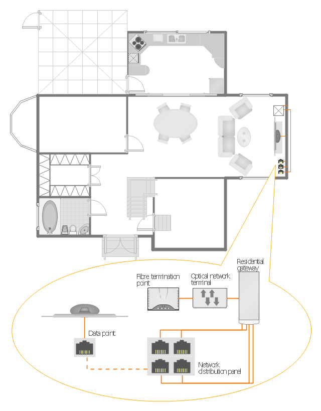
"A home network or home area network (HAN) is a type of local area network that develops from the need to facilitate communication and interoperability among digital devices present inside or within the close vicinity of a home. Devices capable of participating in this network - smart devices such as network printers and handheld mobile computers - often gain enhanced emergent capabilities through their ability to interact. These additional capabilities can then be used to increase the quality of life inside the home in a variety of ways, such as automation of repetitious tasks, increased personal productivity, enhanced home security, and easier access to entertainment." [Home network. Wikipedia]
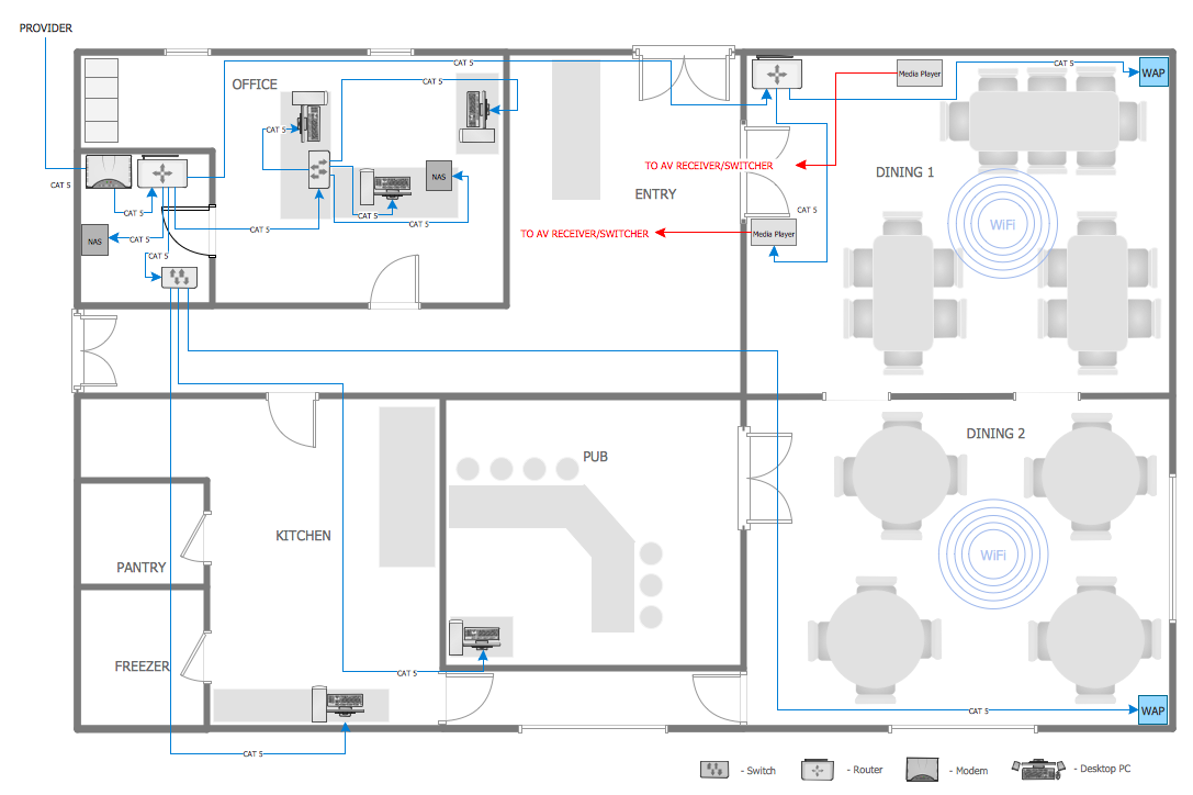
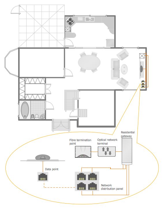
The HAN equipment layout floorplan example "Home network plan" was created using the ConceptDraw PRO diagramming and vector drawing software extended with the Network Layout Floor Plans solution from the Computer and Networks area of ConceptDraw Solution Park.
The HAN equipment layout floorplan example "Home network plan" was created using the ConceptDraw PRO diagramming and vector drawing software extended with the Network Layout Floor Plans solution from the Computer and Networks area of ConceptDraw Solution Park.
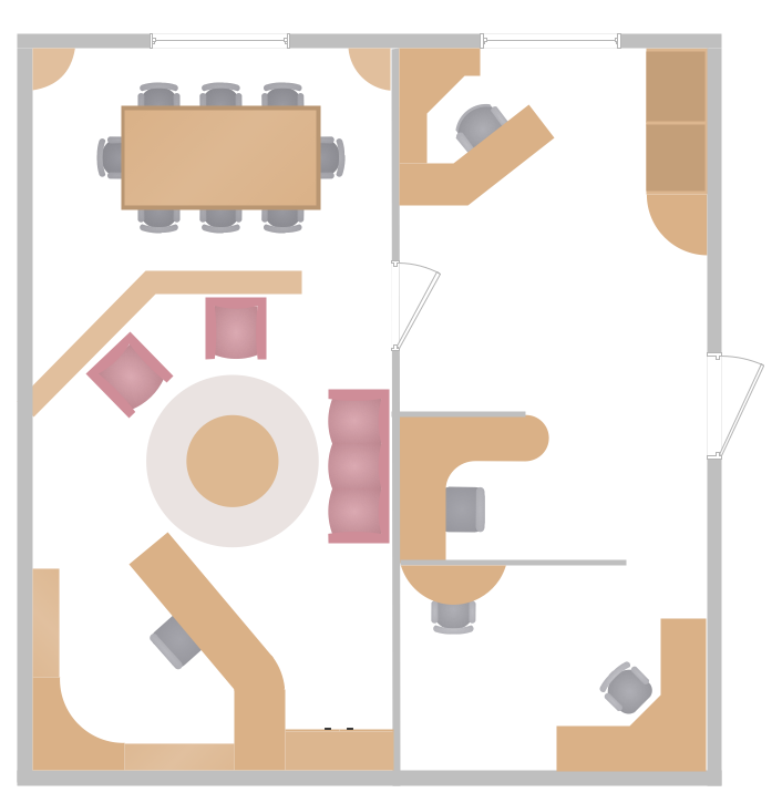
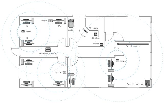
This office floor plan sample depicts the equipment layout of wireless computer network.
"A wireless local area network (WLAN) links two or more devices using some wireless distribution method (typically spread-spectrum or OFDM radio), and usually providing a connection through an access point to the wider Internet. This gives users the ability to move around within a local coverage area and still be connected to the network. Most modern WLANs are based on IEEE 802.11 standards, marketed under the Wi-Fi brand name." [Wireless LAN. Wikipedia]
The equipment layout example "Office wireless network plan" was created using the ConceptDraw DIAGRAM diagramming and vector drawing software extended with the Office Layout Plans solution from the Building Plans area of ConceptDraw Solution Park.
- Network Design Plan Example
- Floor Plan With Computer Networks
- Network Layout Floor Plans | How To Create a Floor Plan in MS ...
- Network Layout Floor Plans | Local area network (LAN). Computer ...
- Network Layout Floor Plans | Local area network (LAN). Computer ...
- Network Layout Floor Plans | Office wireless network plan | Home ...
- Hotel Network Topology Diagram | Hotel Plan . Hotel Plan Examples ...
- Network Layout Floor Plans | Local area network (LAN). Computer ...
- Network Layout Floor Plans | Network Visualization | Local area ...
- Sample Design Plan Of Telephone Layout
- Logical Network Plan Example
- Floor Plan For Computer Networking
- Network Layout | Network Diagram Examples | Design Element ...
- Fishbone diagram - HAN project | Home network plan | Han
- Wireless Networks | Office wireless network plan | Network Diagram ...
- Network Layout Floor Plans | How to Create a Building Plan Using ...
- Network Diagram Examples | How To Make MS Visio Wireless ...
- Network Layout Floor Plans | Local area network (LAN). Computer ...
- Network Layout Floor Plans | Network Diagram Examples | Draw ...


