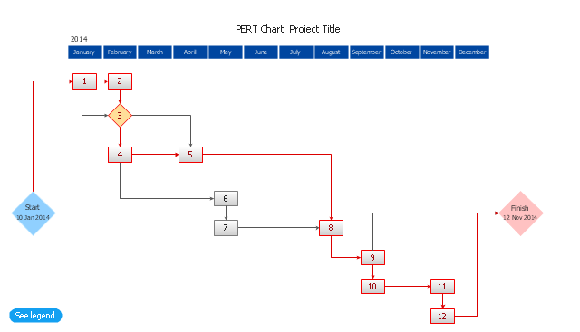
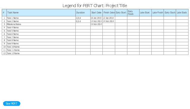
The PERT chart shows the logical connections and consequence of a set of tasks. PERT charts the time period for problem solving and the implementation plan for all activities along the critical path. The PERT chart is also known as a precedence diagram or project network diagram.
"The Program (or Project) Evaluation and Review Technique, commonly abbreviated PERT, is a statistical tool, used in project management, that is designed to analyze and represent the tasks involved in completing a given project. ...
PERT is a method to analyze the involved tasks in completing a given project, especially the time needed to complete each task, and to identify the minimum time needed to complete the total project.
PERT was developed primarily to simplify the planning and scheduling of large and complex projects. ...
A network diagram can be created by hand or by using diagram software. There are two types of network diagrams, activity on arrow (AOA) and activity on node (AON). Activity on node diagrams are generally easier to create and interpret." [Program Evaluation and Review Technique. Wikipedia]
The PERT chart is one of the Seven Management and Planning Tools (7 MP tools, Seven New Quality Tools).
The PERT chart template for the ConceptDraw PRO diagramming and vector drawing software is included in the solution "Seven Management and Planning Tools" from the Management area of ConceptDraw Solution Park.
Product Overview
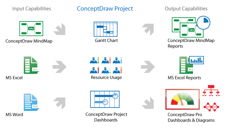
ConceptDraw PROJECT is a vigorous tool for managing single or multiple projects. It lets you determine all essential elements involved into project, control schedules, resources and finances, and monitor projects' progress in most effective yet simple manner.Network Diagram Software
Network Diagrams are used to visually represent the network architecture, to illustrate the network structure, how the computers and other elements of the network are connected each other using a variety of network symbols, clipart and connection lines. They are incredibly useful on the stages of projecting computer network, of its construction and exploitation. Professionally designed and accurate Network Diagrams are equally convenient for computer engineers and users. You can construct them by hand on the paper or use special network diagramming software, such as ConceptDraw DIAGRAM. Having at disposal the powerful network diagramming tools of Computer Network Diagrams solution included to ConceptDraw Solution Park, you can succeed in drawing various types of Computer Network Diagrams, among them Network Communication Plans, Logical Network Diagrams, Network Topology Diagrams, LAN and WAN Diagrams, Network Floor Plan Layouts, Computer Network System Diagrams, Web-based Network Diagrams, Wireless Network Diagrams, Cisco Network Diagram, and others.
 ConceptDraw Solution Park
ConceptDraw Solution Park collects graphic extensions, examples and learning materials
- Network Technique For Project Management
- Activities In A Project Management Software With Example Diagram
- Draw Project Management Nodes
- PERT chart - Project management plan | Program Evaluation and ...
- Activity Network Chart In Softwrae Project Management
- Pert Technique Of Project Planning
- Example Of Pert Chart For Project Management
- PERT chart - Template | Program Evaluation and Review Technique ...
- Program Evaluation and Review Technique (PERT) with ...
- Activity Network Diagram Method | Activity Network (PERT) Chart ...
- PERT chart - Project management plan | Program Evaluation and ...
- Gantt chart examples | Gant Chart in Project Management | Activity ...
- Pert Diagram Example Project Management
- Pert In Software Project Management
- Network Diagram In Project Management
- Activity on Node Network Diagramming Tool | Network Analysis ...
- Pert Chart Project Examples
- Activity Network (PERT) Chart | How To Create a PERT Chart ...
- Activity On Node Diagrams For Project Management On Pdf Format
- Activity Network (PERT) Chart | Program Evaluation and Review ...


