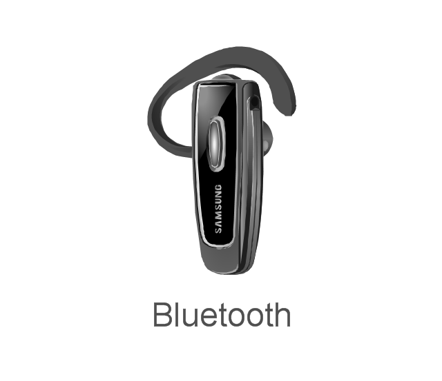
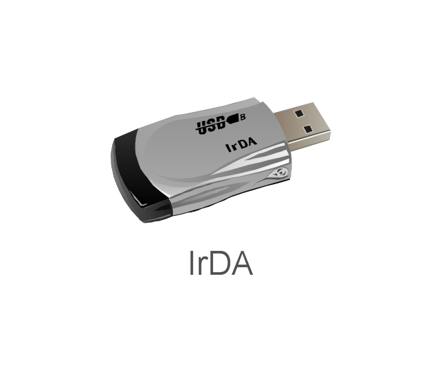
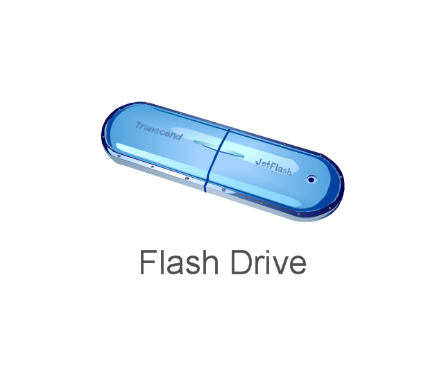
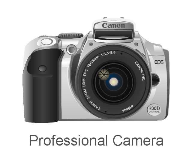
The vector stencils library "External digital devices" contains 15 clipart images of external digital devices and equipment for drawing computer network diagrams.
"Digital electronics, or digital (electronic) circuits, represent signals by discrete bands of analog levels, rather than by a continuous range. All levels within a band represent the same signal state. Relatively small changes to the analog signal levels due to manufacturing tolerance, signal attenuation or parasitic noise do not leave the discrete envelope, and as a result are ignored by signal state sensing circuitry. ...
Digital techniques are useful because it is easier to get an electronic device to switch into one of a number of known states than to accurately reproduce a continuous range of values. ...
An advantage of digital circuits when compared to analog circuits is that signals represented digitally can be transmitted without degradation due to noise. ...
In a digital system, a more precise representation of a signal can be obtained by using more binary digits to represent it. While this requires more digital circuits to process the signals, each digit is handled by the same kind of hardware. ...
Computer-controlled digital systems can be controlled by software, allowing new functions to be added without changing hardware. Often this can be done outside of the factory by updating the product's software. So, the product's design errors can be corrected after the product is in a customer's hands.
Information storage can be easier in digital systems than in analog ones. The noise-immunity of digital systems permits data to be stored and retrieved without degradation. ...
In a digital system, as long as the total noise is below a certain level, the information can be recovered perfectly." [Digital electronics. Wikipedia]
The clip art example "External digital devices - Vector stencils library" was created using the ConceptDraw PRO diagramming and vector drawing software extended with the Computer and Networks solution from the Computer and Networks area of ConceptDraw Solution Park.
www.conceptdraw.com/ solution-park/ computer-and-networks
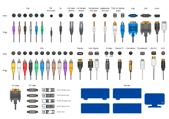
The vector stencils library "Audio and video connectors" contains 94 symbols of audio and video connectors (TRS, TS, XLR, microphone, headphone, TOSLINK, DVI, VGA, DFP, S-Video, RCA, display port, HDMI, Thunderbolt, coaxial TV, F connector, MIDI) and device silhouettes.
Use these jacks and plugs clipart icons for drawing hook up diagrams.
"Audio connectors and video connectors are electrical connectors (or optical connectors) for carrying audio signal and video signal, of either analog or digital format. Analog A/ V connectors often use shielded cables to inhibit radio frequency interference (RFI) and noise." [Audio and video connector. Wikipedia]
"The existence of many different audio and video standards necessitates the definition of hardware interfaces, which define the physical characteristics of the connections between electrical equipment. This includes the types and numbers of wires required along with the strength and frequency of the signal. It also includes the physical design of the plugs and sockets.
An interface may define a connector that is used only by that interface (e.g., DVI) or may define a connector that is also used by another interface; for example, RCA connectors are defined both by the composite video and component video interfaces.
Audio connectors and video connectors are electrical connectors (or optical connectors) for carrying audio signal and video signal, of either analog or digital format. Analog A/ V connectors often use shielded cables to inhibit radio frequency interference (RFI) and noise.
Since both analog and digital signals are used with some styles of connectors, knowledge of the interface used is necessary for a successful transfer of signals. Some interface types use only a distinctive connector or family of connectors, to ensure compatibility. Especially with analog interfaces, physically interchangeable connectors may not carry compatible signals.
Some of these connectors, and other types of connectors, are also used at radio frequency (RF) to connect a radio or television receiver to an antenna or to a cable system..." [Audio and video interfaces and connectors. Wikipedia]
The clipart icons example "Design elements - Audio and video connectors" was created using the ConceptDraw PRO diagramming and vector drawing software extended with the Audio and Video Connectors solution from the Engineering area of ConceptDraw Solution Park.
Audio Connectors
Audio connectors are electrical connectors designed and used for audio frequencies. ConceptDraw PRO diagramming and vector drawing software extended with Audio and Video Connectors Solution from the Engineering Area is the best for drawing various audio schematics with detailed illustration the audio connectors.- Telecommunication networks - Vector stencils library | Noise Clipart ...
- Digital Devices Clipart
- External digital devices - Vector stencils library | External digital ...
- Microphone With Wire Clip Art Png
- Audio Clipart
- Video Format Clipart
- External digital devices - Vector stencils library | Computer network ...
- Noise Symbol Png
- External digital devices - Vector stencils library | Design elements ...
- Signal Clipart
- External digital devices - Vector stencils library | Electrical Symbols ...
- Design elements - Audio and video connectors | Design elements ...
- External digital devices - Vector stencils library | Using Both Wired ...
- Standard Universal Audio & Video Connection Types | Design ...
- Mountain Antenna Clipart
- Clip Art Banquite Tables
- Cell Wave Clipart
- Audio & Video Connector Types | Design elements - Audio and ...
- Standard Universal Audio & Video Connection Types | Audio Visual ...
- Design elements - Android system icons (av) | Design elements ...
