HelpDesk
How to Create an ERD Diagram
 using Chen's notation")
The vector stencils library "Internal block diagram" contains 22 SysML symbols.
Use it to design your internal block diagrams using ConceptDraw PRO diagramming and vector drawing software.
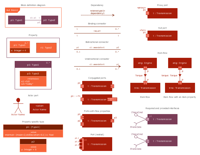
"Internal Block Diagram
An internal block diagram is based on the UML composite structure diagram, with restrictions and extensions as defined
by SysML. ...
Property types
Four general categories of properties of blocks are recognized in SysML: parts, references, value properties, and
constraint properties. ... A part or value property is always shown on an internal block diagram with a solid-outline box. A reference property is shown by a dashed-outline box, consistent with UML. Ports are special cases of properties, and have a variety of notations... Constraint properties and their parameters also have their own notations... " [www.omg.org/ spec/ SysML/ 1.3/ PDF]
The SysML shapes example "Design elements - Internal block diagram" is included in the SysML solution from the Software Development area of ConceptDraw Solution Park.
Use it to design your internal block diagrams using ConceptDraw PRO diagramming and vector drawing software.
"Internal Block Diagram
An internal block diagram is based on the UML composite structure diagram, with restrictions and extensions as defined
by SysML. ...
Property types
Four general categories of properties of blocks are recognized in SysML: parts, references, value properties, and
constraint properties. ... A part or value property is always shown on an internal block diagram with a solid-outline box. A reference property is shown by a dashed-outline box, consistent with UML. Ports are special cases of properties, and have a variety of notations... Constraint properties and their parameters also have their own notations... " [www.omg.org/ spec/ SysML/ 1.3/ PDF]
The SysML shapes example "Design elements - Internal block diagram" is included in the SysML solution from the Software Development area of ConceptDraw Solution Park.
Internal block diagram symbols
 Entity-Relationship Diagram (ERD)
Entity-Relationship Diagram (ERD) solution extends ConceptDraw PRO software with templates, samples and libraries of vector stencils from drawing the ER-diagrams by Chen's and crow’s foot notations.
HelpDesk
How to Draw a Block Diagram in ConceptDraw PRO

- UML Block Diagram
- What Is The Symbol And Notation For Composite Structure Diagram
- UML Class Diagram Notation
- UML Class Diagram Notation
- UML Block Diagram | About UML | UML Notation | Relationship In ...
- Block Diagram | Basic Flowchart Symbols and Meaning | UML Block ...
- UML Class Diagram Generalization Example
- UML Block Diagram | Entity-Relationship Diagram (ERD) | UML ...
- UML Block Diagram
- Design elements - ER diagram (Chen notation )
- UML Block Diagram | UML Diagram | UML Class Diagram Notation ...
- UML Notation | UML Class Diagram Notation | UML Diagram | Uml ...
- UML Notation | Entity-Relationship Diagram (ERD) | UML Diagram ...
- Class Diagram For Export Medical System
- UML Class Diagram Notation | Entity-Relationship Diagram (ERD ...
- Process Flowchart | UML Diagram | UML Class Diagram Notation ...
- UML Class Diagram Notation
- UML Class Diagram Example - Medical Shop | UML Diagram for ...
- Entity Relationship Diagram Symbols | Basic Flowchart Symbols and ...
- UML Notation | Business Process Modeling with ConceptDraw ...